Page 3773 of 5598

MWI-30
< SYSTEM DESCRIPTION >
DIAGNOSIS SYSTEM (COMBINATION METER)
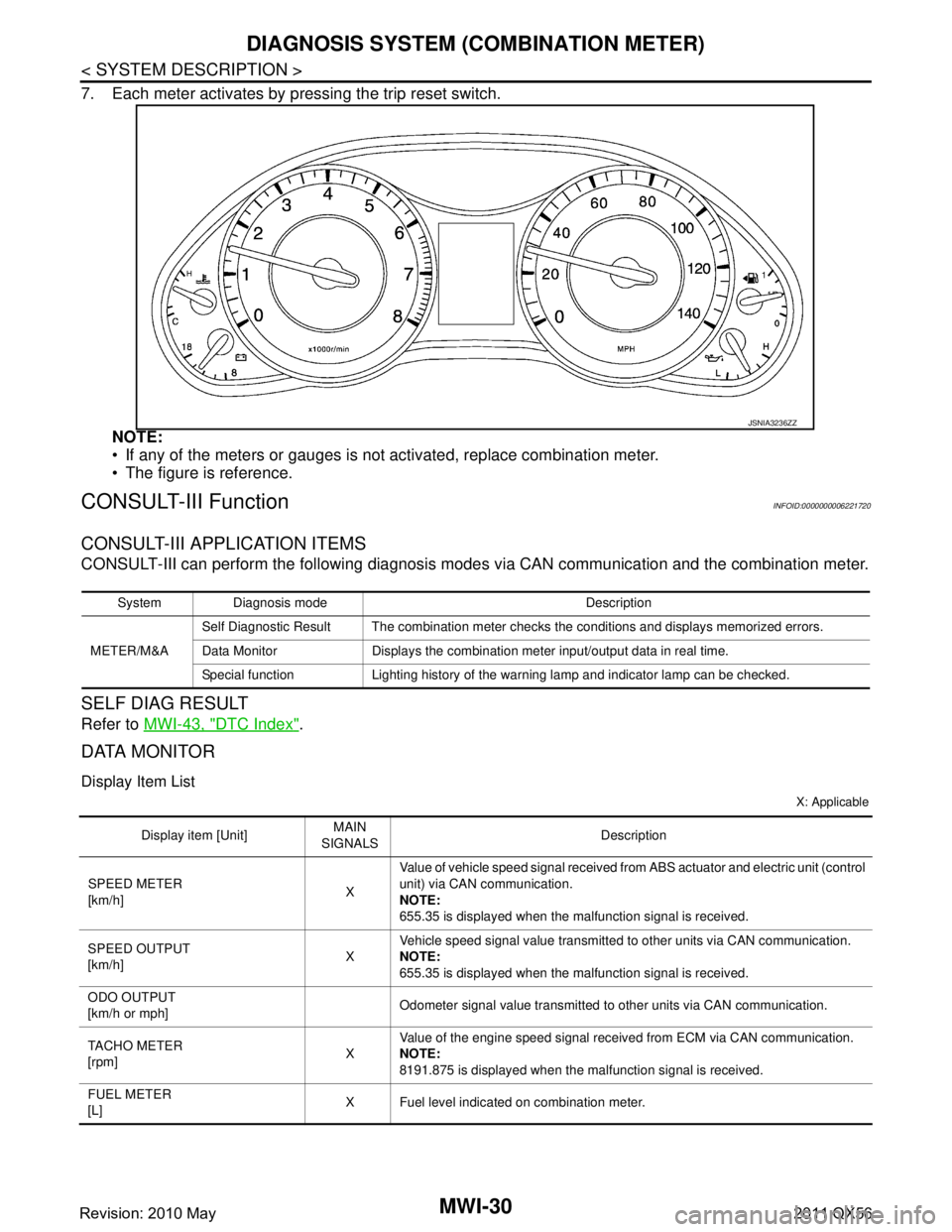
7. Each meter activates by pressing the trip reset switch.NOTE:
If any of the meters or gauges is not activated, replace combination meter.
The figure is reference.
CONSULT-III FunctionINFOID:0000000006221720
CONSULT-III APPLICATION ITEMS
CONSULT-III can perform the following diagnosis modes via CAN communication and the combination meter.
SELF DIAG RESULT
Refer to MWI-43, "DTC Index".
DATA MONITOR
Display Item List
X: Applicable
JSNIA3236ZZ
System Diagnosis mode Description
METER/M&A Self Diagnostic Result The combination meter checks the conditions and displays memorized errors.
Data Monitor Displays the combination meter input/output data in real time.
Special function Lighting history of the warning lamp and indicator lamp can be checked.
Display item [Unit]
MAIN
SIGNALS Description
SPEED METER
[km/h] XValue of vehicle speed
signal received from ABS actuator and el ectric unit (control
unit) via CAN communication.
NOTE:
655.35 is displayed when the malfunction signal is received.
SPEED OUTPUT
[km/h] XVehicle speed signal value transmitted to other units via CAN communication.
NOTE:
655.35 is displayed when the malfunction signal is received.
ODO OUTPUT
[km/h or mph] Odometer signal value transmitted to other units via CAN communication.
TACHO METER
[rpm] XValue of the engine speed signal received from ECM via CAN communication.
NOTE:
8191.875 is displayed when the malfunction signal is received.
FUEL METER
[L] X Fuel level indicated on combination meter.
Revision: 2010 May2011 QX56
Page 3782 of 5598

MWI
COMBINATION METERMWI-39
< ECU DIAGNOSIS INFORMATION >
C
DE
F
G H
I
J
K L
M B A
O P
NOTE:
Some items are not available according to vehicle specification.
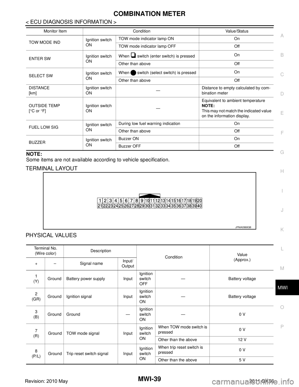
TERMINAL LAYOUT
PHYSICAL VALUES
TOW MODE IND Ignition switch
ONTOW mode indicator lamp ON On
TOW mode indicator lamp OFF Off
ENTER SW Ignition switch
ONWhen switch (enter switch) is pressed
On
Other than above Off
SELECT SW Ignition switch
ONWhen switch (select switch) is pressed
On
Other than above Off
DISTANCE
[km] Ignition switch
ON
—Distance to empty calculated by com-
bination meter
OUTSIDE TEMP
[ ° C or °F] Ignition switch
ON
—Equivalent to ambient temperature
NOTE:
This may not match the indicated value
on the information display.
FUEL LOW SIG Ignition switch
ONDuring low fuel warning indication On
Other than above Off
BUZZER Ignition switch
ONBuzzer ON On
Buzzer OFF Off
Monitor Item Condition Value/Status
JPNIA0968GB
Te r m i n a l N o .
(Wire color) Description
ConditionVa l u e
(Approx.)
+ – Signal name Input/
Output
1
(Y) Ground Battery power supply Input Ignition
switch
OFF— Battery voltage
2
(GR) Ground Ignition signal Input Ignition
switch
ON
— Battery voltage
3
(B) Ground Ground — Ignition
switch
ON—0 V
7
(R) Ground TOW mode signal Input Ignition
switch
ONWhen TOW mode switch is
pressed
0 V
Other than the above 12 V
8
(P/L) Ground Trip reset switch signal Input Ignition
switch
ONWhen trip reset switch is
pressed
0 V
Other than the above 5 V
Revision: 2010 May2011 QX56
Page 3785 of 5598

MWI-42
< ECU DIAGNOSIS INFORMATION >
COMBINATION METER
Fail-Safe
INFOID:0000000006221722
FA I L - S A F E
The combination meter activates the fail-safe contro l if CAN communication with each unit is malfunctioning.
37
(R/Y) Ground Non-manual mode signal Input Ignition
switch
ONSelector manual mode po-
sition
12 V
Other than the above 0 V
38
(L/W) Ground Manual mode shift down
signal InputIgnition
switch
ON Selector lever DOWN oper-
ation
0 V
Other than the above 12 V
39
(Y/B) Ground Manual mode shift up sig-
nal InputIgnition
switch
ON Selector lever UP operation 0 V
Other than the above 12 V
40
(G/W) Ground Manual mode signal Input Ignition
switch
ONSelector manual mode po-
sition
0 V
Other than the above 12 V
Te r m i n a l N o .
(Wire color) Description
ConditionVa l u e
(Approx.)
+ – Signal name Input/
Output
Function Specifications
Speedometer
Reset to zero by suspending communication.
Tachometer
Engine coolant temperature gauge
Engine oil pressure gauge
Illumination control When suspending communication, changes to nighttime mode.
Information display Odo/trip meter An indicated value is maintained at communications blackout.
Shift position indicator The display turns OFF by suspending communication.
Door open warning The display turns OFF by suspending communication.
Buzzer The buzzer turns OFF by suspending communication.
Revision: 2010 May2011 QX56
Page 3808 of 5598

MWI
TRIP RESET AND ILLUMINATION CONTROL SWITCH SIGNAL CIRCUIT
MWI-65
< DTC/CIRCUIT DIAGNOSIS >
C
D E
F
G H
I
J
K L
M B A
O P
TRIP RESET AND ILLUMINATION CO NTROL SWITCH SIGNAL CIRCUIT
Diagnosis ProcedureINFOID:0000000006221744
1.CHECK COMBINATION METER INPUT SIGNAL
1. Turn ignition switch ON.
2. Measure voltage between the following terminals of the combination meter.
Is the inspection result normal?
YES >> INSPECTION END
NO >> GO TO 2.
2.CHECK TRIP RESET AND ILLUMINATION CONTROL SWITCH SIGNAL CIRCUIT
1. Turn ignition switch OFF.
2. Disconnect combination meter connector and trip reset and illumination control switch connector.
3. Check continuity between combination meter harness connector and trip reset and illumination control switch harness connector.
4. Check continuity between combination meter harness connector and ground.
Is the inspection result normal?
YES >> GO TO 3.
NO >> Repair harness or connector.
3.CHECK TRIP RESET AND ILLUMINATI ON CONTROL SWITCH GROUND CIRCUIT
Check continuity between trip reset and i llumination control switch connector and ground.
(+) (−)
Condition Voltag e
(Approx.)
Combination meter
Ground
Connector Terminals
M34 8
When trip reset switch is pressed 0 V
Other than the above 5 V
13 When illumination control switch (+) is pressed 0 V
Other than the above 5 V
14 When illumination control switch (
−) is pressed 0 V
Other than the above 5 V
Te r m i n a l s Continuity
Combination meter Trip reset and illumination control switch
Connector Terminal Connector Terminal
M34 8
M83 5
Existed
13 3
14 4
Combination meter GroundContinuity
Connector Terminal
M34 8
Not existed
13
14
Trip reset and illumination control switch
GroundContinuity
Connector Terminal
M83 6 Existed
Revision: 2010 May2011 QX56
Page 3809 of 5598
MWI-66
< DTC/CIRCUIT DIAGNOSIS >
TRIP RESET AND ILLUMINATION CONTROL SWITCH SIGNAL CIRCUIT
Is the inspection result normal?
YES >> INSPECTION END
NO >> Repair harness or connector.
Component InspectionINFOID:0000000006221745
1.CHECK TRIP RESET AND ILLUMINATION CONTROL SWITCH
1. Turn ignition switch OFF.
2. Disconnect trip reset and illumination control switch connector.
3. Check trip reset and illumination control switch.
Is the inspection result normal?
YES >> INSPECTION END
NO >> Replace trip reset and illumination control switch. Refer to MWI-86, "
Removal and Installation".
Te r m i n a l s
Condition Continuity
Trip reset and illumina-
tion control switch
5
6When trip reset switch is pressed Existed
Other than the above Not existed
3 When illumination control switch (+) is pressed Existed
Other than the above Not existed
4 When illumination control switch (
−) is pressed Existed
Other than the above Not existed
Revision: 2010 May2011 QX56
Page 3819 of 5598

MWI-76
< SYMPTOM DIAGNOSIS >
THE TRIP RESET AND ILLUMINATION CONTROL SWITCH IS INOPERATIVE
THE TRIP RESET AND ILLUMINATION CONTROL SWITCH IS INOPERA-
TIVE
DescriptionINFOID:0000000006221759
If any of the following malfunctions is found for t he trip reset and illumination control switch operation.
All switches are inoperative
The specified switch cannot be operated
Diagnosis ProcedureINFOID:0000000006221760
1.CHECK TRIP RESET AND ILLUMINATI ON CONTROL SWITCH SIGNAL CIRCUIT
Check the trip reset and illumination cont rol switch signal circuit. Refer to MWI-65, "
Diagnosis Procedure".
Is the inspection result normal?
YES >> GO TO 2.
NO >> Repair harness or connector.
2.CHECK TRIP RESET AND ILLU MINATION CONTROL SWITCH
Perform a unit check for the trip reset and illumination control switch. Refer to MWI-66, "
Component Inspec-
tion".
Is the inspection result normal?
YES >> Replace combination meter. Refer to MWI-85, "Removal and Installation".
NG >> Replace trip reset and illumination control switch. Refer to MWI-86, "
Removal and Installation".
Revision: 2010 May2011 QX56
Page 3829 of 5598
MWI-86
< REMOVAL AND INSTALLATION >
TRIP RESET AND ILLUMINATION CONTROL SWITCH
TRIP RESET AND ILLUMINATION CONTROL SWITCH
Exploded ViewINFOID:0000000006221779
REMOVAL
Refer to IP-13, "Exploded View".
Removal and InstallationINFOID:0000000006221780
REMOVAL
1. Remove cluster lid A. Refer to IP-14, "Removal and Installation".
2. Remove clip.
3. Press pawls and remove trip reset and illumination control switch.
INSTALLATION
Install in the reverse order of removal.
Revision: 2010 May2011 QX56
Page 3878 of 5598
![INFINITI QX56 2011 Factory Service Manual
PCS
SYSTEMPCS-37
< SYSTEM DESCRIPTION > [POWER DISTRIBUTION SYSTEM]
C
D
E
F
G H
I
J
K L
B A
O P
N
SYSTEM
POWER DISTRIBUTION SYSTEM
POWER DISTRIBUTION SYSTEM : System DiagramINFOID:0000000006220196
PO INFINITI QX56 2011 Factory Service Manual
PCS
SYSTEMPCS-37
< SYSTEM DESCRIPTION > [POWER DISTRIBUTION SYSTEM]
C
D
E
F
G H
I
J
K L
B A
O P
N
SYSTEM
POWER DISTRIBUTION SYSTEM
POWER DISTRIBUTION SYSTEM : System DiagramINFOID:0000000006220196
PO](/manual-img/42/57033/w960_57033-3877.png)
PCS
SYSTEMPCS-37
< SYSTEM DESCRIPTION > [POWER DISTRIBUTION SYSTEM]
C
D
E
F
G H
I
J
K L
B A
O P
N
SYSTEM
POWER DISTRIBUTION SYSTEM
POWER DISTRIBUTION SYSTEM : System DiagramINFOID:0000000006220196
POWER DISTRIBUTION SYST
EM : System DescriptionINFOID:0000000006220197
SYSTEM DESCRIPTION
PDS (POWER DISTRIBUTION SYSTEM) is the system that BCM controls with the operation of the push-
button ignition switch and performs the power distributi on to each power circuit. This system is used instead
of the mechanical power supply changing mechanism wit h the operation of the conventional key cylinder.
The push-button ignition switch can be operated when Intelligent Key is in the following condition. Refer to Engine Start Function for details.
- Intelligent Key is in the detection area of the inside key antenna.
- Intelligent Key backside is contact ed to push-button ignition switch.
The push-button ignition switch operation is input to BCM as a signal. BCM changes the power supply posi-
tion according to the status and operates the follo wing relays to supply power to each power circuit.
- Ignition relay (inside IPDM E/R)
- Ignition relay-1
- ACC relay
- Blower relay
NOTE:
The engine switch operation changes due to the conditions of brake pedal, selector lever and vehicle speed.
The power supply position can be confirmed with the light ing of the indicators near the push-button ignition
switch.
BATTERY SAVER SYSTEM
When all the following conditions are met for 60 minutes, the battery saver system will cut off the power supply
to prevent battery discharge.
The ignition switch is in the ACC position
All doors are closed
Selector lever is in the P position
Reset Condition of Battery Saver System
In order to prevent the battery from discharging, the battery saver system will cut off the power supply when all
doors are closed, the selector lever is on P position and t he ignition switch is left on ACC position for 1 hour. If
any of the following conditions are met the battery saver system is released and the steering will change auto-
matically to lock position from OFF position.
Opening any door
Operating with door request switch on door lock
Operating with Intelligent Key on door lock
Press push-button ignition switch and ignition swit ch will change to ACC position from OFF position.
JMMIA0444GB
Revision: 2010 May2011 QX56