2011 INFINITI QX56 reset
[x] Cancel search: resetPage 4790 of 5598

DIAGNOSIS SENSOR UNITSR-27
< REMOVAL AND INSTALLATION >
C
DE
F
G
I
J
K L
M A
B
SR
N
O P
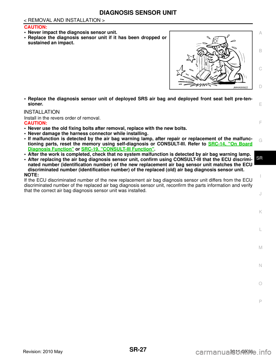
CAUTION:
Never impact the diagnosis sensor unit.
Replace the diagnosis sensor uni t if it has been dropped or
sustained an impact.
Replace the diagnosis sensor unit of deployed SRS air bag and deployed front seat belt pre-ten-
sioner.
INSTALLATION
Install in the revers order of removal.
CAUTION:
Never use the old fixing bolts afte r removal, replace with the new bolts.
Never damage the harness co nnector while installing.
If malfunction is detected by the air bag warnin g lamp, after repair or replacement of the malfunc-
tioning parts, reset the memory using sel f-diagnosis or CONSULT-III. Refer to SRC-14, "
On Board
Diagnosis Function" or SRC-19, "CONSULT-III Function".
After the work is completed, check that no system malfunction is detected by air bag warning lamp.
After replacing the air bag diag nosis sensor unit, confirm using CO NSULT-III that the ECU discrimi-
nated number (identification nu mber) of the new replacement air bag sensor unit matches the ECU
discriminated number (identification number) of the replaced (old) air bag diagnosis sensor unit.
NOTE:
If the ECU discriminated number of the new replacement air bag diagnosis sensor unit differs from the ECU
discriminated number of the replaced air bag diagnosis sens or unit, reconfirm the parts information and verify
that the correct air bag diagnosis sensor unit was installed.
JMHIA0009ZZ
Revision: 2010 May2011 QX56
Page 4794 of 5598

SRC-1
RESTRAINTS
C
DE
F
G
I
J
K L
M
SECTION SRC
A
B
SRC
N
O P
CONTENTS
SRS AIRBAG CONTROL SYSTEM
PRECAUTION ................ ...............................6
PRECAUTIONS .............................................. .....6
Precaution for Supplemental Restraint System
(SRS) "AIR BAG" and "SEAT BELT PRE-TEN-
SIONER" ............................................................. ......
6
Service ......................................................................6
SYSTEM DESCRIPTION ..............................8
COMPONENT PARTS ................................... .....8
Component Parts Location .................................. ......8
Component Description .............................................9
SYSTEM .............................................................11
System Diagram .................................................. ....11
System Description .................................................12
DIAGNOSIS SYSTEM (AIR BAG) .....................14
Description .......................................................... ....14
On Board Diagnosis Function .................................14
CONSULT-III Function ............................................19
DIAGNOSIS SYSTEM (OCCUPANT DETEC-
TION SYSTEM) .............................................. ....
21
CONSULT-III Function ........................................ ....21
ECU DIAGNOSIS INFORMATION ..............22
DIAGNOSIS SENSOR UNIT .......................... ....22
DTC Index .......................................................... ....22
WIRING DIAGRAM ......................................27
SRS AIR BAG SYSTEM ................................. ....27
Wiring Diagram ................................................... ....27
BASIC INSPECTION ...................................36
DIAGNOSIS AND REPAIR WORK FLOW .... ....36
Work Flow ........................................................... ....36
INSPECTION AND ADJUSTMENT ....................39
ADDITIONAL SERVICE WHEN REPLACING
CONTROL UNIT .................................................... ....
39
ADDITIONAL SERVICE WHEN REPLACING
CONTROL UNIT : Description .................................
39
ADDITIONAL SERVICE WHEN REPLACING
CONTROL UNIT : Special Repair Requirement ......
39
ZERO POINT RESET ............................................. ....39
ZERO POINT RESET : Description .........................39
ZERO POINT RESET : Special Repair Require-
ment .........................................................................
39
DTC/CIRCUIT DIAGNOSIS .........................41
B1001, B1002, B1003, B1004, B1005 DIAG-
NOSIS SENSOR UNIT ......................................
41
DTC Logic ............................................................ ....41
Diagnosis Procedure ...............................................41
B1006, B1007, B1008, B1009, B1010 DIAG-
NOSIS SENSOR UNIT ......................................
42
DTC Logic ................................................................42
Diagnosis Procedure ...............................................42
B1011, B1012, B1013, B1014, B1015 DIAG-
NOSIS SENSOR UNIT ......................................
43
DTC Logic ................................................................43
Diagnosis Procedure ...............................................43
B1017, B1020, B1021 OCCUPANT SENS C/U
...
44
Description ........................................................... ....44
DTC Logic ................................................................44
Diagnosis Procedure ...............................................44
B1018 OCCUPANT SENS ................................46
Description ........................................................... ....46
DTC Logic ................................................................46
Diagnosis Procedure ...............................................46
B1022 OCCUPANT SENS C/U .........................48
Description ...............................................................48
Revision: 2010 May2011 QX56
Page 4805 of 5598

SRC-12
< SYSTEM DESCRIPTION >
SYSTEM
System Description
INFOID:0000000006219951
Supplemental Restraint System (SRS ) activates air bag module and seat belt pre-tensioner when it detects a
frontal collision or a side collision or rollover that is more than the specified limit. Together with other safety
devices, it reduces the impact that occup ant receives when vehicle collision occurs.
Air bag diagnosis sensor unit supplies power supply to air bag module and pre-tensioner seat belt when decel-
eration that is more than the specified limit is detec ted by G sensor in air bag diagnosis sensor unit, crash
zone sensor, or satellite sensor. Air bag module is composed of electric igniter (squib), filter, pyrotechnic mate-
rial, and gas generating material. When air bag module re ceives a signal from air bag diagnosis sensor unit,
air bag module ignites pyrotechnic material using electric igniter (squib) so that gas generating material gener-
ates high temperature nitrogen gas. The gas through filter activates air bag. At the same time, pre-tensioner
seat belt receives power supply from air bag diagnosis sensor unit, gasgenerator is activated, and then gas is
generated. Balls in pipe are moved according to generated gas pressure and strike pinion gear on ELR shaft.
ELR shaft rotates and retracts seat belt.
AIR BAG DIAGNOSIS SENSOR UNIT FUNCTIONS
Air bag diagnosis sensor unit has the following functions.
Detects a collision and supplies the energy for deploying air bag and seat belt pre-tensioner.
Detects and records electrical malfunction in air bag system and seat belt pre-tensioner system, and blinking
air bag warning lamp.
Detects and records the deployment of air bag and s eat belt pre-tensioner, and turns ON air bag warning
lamp.
Indicates malfunctioning portion via the number of blin ks from the air bag warning lamp in the diagnosis
mode.
Indicates the malfunction record via CONSULT-III.
COLLISION MODES
The operation of SRS is different depending on the collision modes applications.
SRS configurations that are activa ted for the following collision modes.
×: Apply —: Not apply
OCCUPANT DETECTION SYSTEM
This Occupant Detection System has the following functions.
1. Suppress the deployment of front passenger air bag w hen front passenger seat is empty, or when occu-
pied by child and child-seat. Turns ON front passenger air bag OFF indicator when front passenger seat is
occupied by child-seat and child.
2. Indicates malfunction portion with blinking times of air bag warning lamp in diagnosis mode.
3. Indicates the malfunctioning record by CONSULT-III.
4. When “zero point reset” for occupant detection system is incomplete, CONSULT-III indicates that “zero
point reset” is incomplete.
This function is applied to NISSAN genuine parts only.
NOTE:
SRS configuration Frontal collision Left side collision Right side collision Roll over
Driver air bag module ×———
Passenger air bag module ×———
Seat belt pre-tensioner LH ××—×
Seat belt pre-tensioner RH ×— ××
Lap pre-tensioner LH ××—×
Lap pre-tensioner RH ×— ××
Side air bag module LH — ×——
Side air bag module RH — — ××
Front curtain air bag module LH — ×— ×
Front curtain air bag module RH — — ××
Rear curtain air bag module LH — ×— ×
Rear curtain air bag module RH — — ××
Revision: 2010 May2011 QX56
Page 4806 of 5598

SYSTEMSRC-13
< SYSTEM DESCRIPTION >
C
DE
F
G
I
J
K L
M A
B
SRC
N
O P
Operation of air bag diagnosis sensor unit when air bag diagnosis sensor unit receives information from Occupant Detection System.
Even if zero point reset is “complete”, always perfo rm zero point reset after the removal and installation of
seat or the removal of control unit harness connector.
Status (front passenger
seat) Passenger air bag Front passenger air
bag OFF indicatorAir bag warning lamp
Seat belt warning lamp
(when front passenger
seat is unbuckled)
Empty Suppress OFF OFF OFF
An object Suppress ON OFF OFF
Child/ child-seat Suppress ON OFF ON
Adult Enable to deploy OFF OFF ON
Malfunction Suppress ON Blinking OFF
Zero point reset
Not yet performed (NIS-
SAN genuine parts
only) Suppress ON Blinking OFF
Revision: 2010 May2011 QX56
Page 4814 of 5598

DIAGNOSIS SYSTEM (OCCUPANT DETECTION SYSTEM)
SRC-21
< SYSTEM DESCRIPTION >
C
D E
F
G
I
J
K L
M A
B
SRC
N
O P
DIAGNOSIS SYSTEM (OCCUP ANT DETECTION SYSTEM)
CONSULT-III FunctionINFOID:0000000006219955
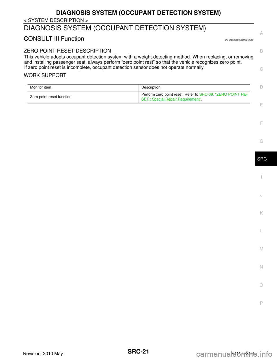
ZERO POINT RESET DESCRIPTION
This vehicle adopts occupant detection system with a we ight detecting method. When replacing, or removing
and installing passenger seat, always perform “zero point rest” so that the vehicle recognizes zero point.
If zero point reset is incomplete, occupant detection sensor does not operate normally.
WORK SUPPORT
Monitor item Description
Zero point reset function Perform zero point reset. Refer to
SRC-39, "
ZERO POINT RE-
SET : Special Repair Requirement".
Revision: 2010 May2011 QX56
Page 4832 of 5598

INSPECTION AND ADJUSTMENTSRC-39
< BASIC INSPECTION >
C
DE
F
G
I
J
K L
M A
B
SRC
N
O P
INSPECTION AND ADJUSTMENT
ADDITIONAL SERVICE WHEN REPLACING CONTROL UNIT
ADDITIONAL SERVICE WHEN REPL ACING CONTROL UNIT : Description
INFOID:0000000006219959
When replacing or removing and installing passenger seat, always perform zero point reset so that Occupant
Detection System is activated normally.
ADDITIONAL SERVICE WHEN REPLACING CONTROL UNIT : Special Repair Re-
quirement
INFOID:0000000006219960
WORK PROCEDURE WHEN REPLACING CONTROL UNIT
1.PERFORM ZERO POINT RESET
Perform zero point reset. Refer to SRC-39, "
ZERO POINT RESET : Special Repair Requirement".
>> END
ZERO POINT RESET
ZERO POINT RESET : DescriptionINFOID:0000000006219961
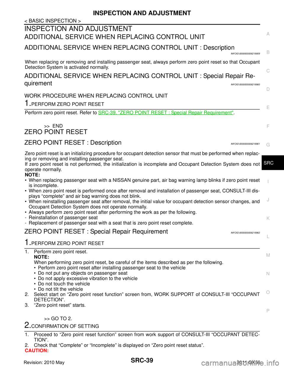
Zero point reset is an initializing procedure for occupant detection sensor that must be performed when replac-
ing or removing and installing passenger seat.
If zero point reset is not performed, the initializati on is incomplete and Occupant Detection System does not
operate normally.
NOTE:
When replacing passenger seat with a NISSAN genuine part, air bag warning lamp blinks if zero point reset
is incomplete.
When zero point reset is performed once after removal and installation of passenger seat, CONSULT-III dis-
plays “complete” and air bag warning does not blink.
When reinstalling passenger seat after removal, the initial value for occupant detection sensor changes, and
Occupant Detection System does not operate normally.
Always perform zero point reset after performing the work as per the following.
- Reinstallation of passenger seat
- Replacement of passenger seat with a seat that is zero point reset complete.
ZERO POINT RESET : Special Repair RequirementINFOID:0000000006219962
1.PERFORM ZERO POINT RESET
1. Perform zero point reset. NOTE:
When performing zero point reset, be careful of the items described as per the following.
Perform zero point reset after installing passenger seat to the vehicle
Do not put any objects on passenger seat
Do not apply excessive vibration to the vehicle
Do not touch the vehicle
Do not tilt the vehicle
2. Select start on “Zero point reset function” scr een from, WORK SUPPORT of CONSULT-III “OCCUPANT
DETECTION”.
3. “Zero point reset” starts.
>> GO TO 2.
2.CONFIRMATION OF SETTING
1. Proceed to “Zero point reset function” screen fr om work support of CONSULT-III “OCCUPANT DETEC-
TION”.
2. Check that “Complete” or “Incomplete” is displayed on “Zero point reset status”.
CAUTION:
Revision: 2010 May2011 QX56
Page 4833 of 5598

SRC-40
< BASIC INSPECTION >
INSPECTION AND ADJUSTMENT
“Complete” is displayed on “zero point reset current status” if the seat is reinstalled by seat removal
and installation, or “zero poin t reset” is already performed.
“Zero point reset current status” displays “Incompl ete” if a new seat is installed. When turning key
switch ON without performing zero point reset, air bag warning lamp blinks. When zero point reset is
performed, air bag wa rning lamp turns OFF.
Air bag warning lamp blinks in user mode only.
Air bag sensor unit does not record whethe r or not zero point reset is performed.
Is condition
“ALREADY PERFORMED”?
YES >> Print out “ZERO POINT RESET CURRENT STATUS” screen, and inspection end.
NO >> Check condition as per the following, and perform zero point reset again. Passenger seat is occupied by an object.
Excessive vibration is applied while performing zero point reset.
Occupant detection system is malfunctioning.NOTE:
If “Incomplete” is displayed on “zero point reset cu rrent status”, zero point reset is not completed
normally. Check the condition as per the following and perform zero point reset again.
Passenger seat is occupied by an object.
Excessive vibration is applied while performing zero point reset.
Occupant detection system is malfunctioning.
Revision: 2010 May2011 QX56
Page 5411 of 5598

WCS
SYSTEMWCS-7
< SYSTEM DESCRIPTION >
C
DE
F
G H
I
J
K L
M B A
O P
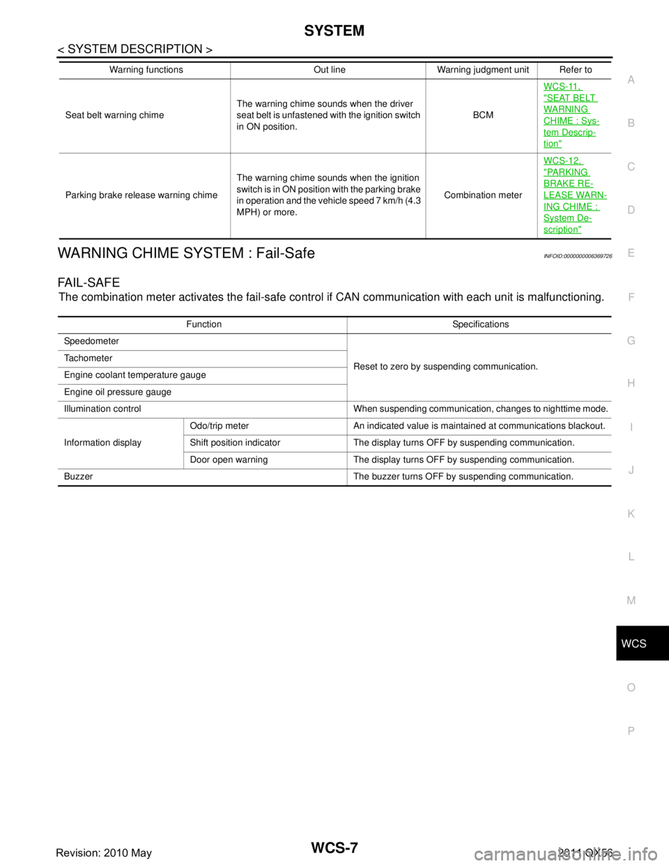
WARNING CHIME SYSTEM : Fail-SafeINFOID:0000000006369726
FA I L - S A F E
The combination meter activates the fail-safe contro l if CAN communication with each unit is malfunctioning.
Seat belt warning chimeThe warning chime sounds when the driver
seat belt is unfastened with the ignition switch
in ON position. BCMWCS-11,
"SEAT BELT
WARNING
CHIME : Sys-
tem Descrip-
tion"
Parking brake release warning chime
The warning chime sounds when the ignition
switch is in ON position with the parking brake
in operation and the vehicle speed 7 km/h (4.3
MPH) or more. Combination meterWCS-12,
"PA R K I N G
BRAKE RE-
LEASE WARN-
ING CHIME :
System De-
scription"
Warning functions Out line Warning judgment unit Refer to
Function Specifications
Speedometer
Reset to zero by suspending communication.
Tachometer
Engine coolant temperature gauge
Engine oil pressure gauge
Illumination control When suspending communication, changes to nighttime mode.
Information display Odo/trip meter An indicated value is maintained at communications blackout.
Shift position indicator The display turns OFF by suspending communication.
Door open warning The display turns OFF by suspending communication.
Buzzer The buzzer turns OFF by suspending communication.
Revision: 2010 May2011 QX56