Page 4627 of 5598
![INFINITI QX56 2011 Factory Service Manual
SEC-20
< SYSTEM DESCRIPTION >[WITH INTELLIGENT KEY SYSTEM]
SYSTEM
this time, if BCM still detects unauthorized access to t
he vehicle, the system is switched to the ALARM phase
again. This RE-ALARM o INFINITI QX56 2011 Factory Service Manual
SEC-20
< SYSTEM DESCRIPTION >[WITH INTELLIGENT KEY SYSTEM]
SYSTEM
this time, if BCM still detects unauthorized access to t
he vehicle, the system is switched to the ALARM phase
again. This RE-ALARM o](/manual-img/42/57033/w960_57033-4626.png)
SEC-20
< SYSTEM DESCRIPTION >[WITH INTELLIGENT KEY SYSTEM]
SYSTEM
this time, if BCM still detects unauthorized access to t
he vehicle, the system is switched to the ALARM phase
again. This RE-ALARM operation is carried out a maximum of 2 times.
To cancel the ALARM operation, refer to the switching condition of No. 12 in the table above.
NOTE:
If a battery terminal is disconnected during the ALARM phase, theft warning alarm stops. But when the battery
terminal is reconnected, theft warning alarm is activated again.
PRE-RESET Phase
The PRE-RESET phase is the transient state betw een each phase and DISARMED phase. If only the condi-
tion of hood is not satisfied, the system switches to the PRE-RESET phase. Then, when any condition is
changed, the system switches to t he DISARMED phase or PRE-ARMED phase.
PANIC ALARM
The panic alarm function activates horns and headlamps intermittently when the owner presses the PANIC
ALARM button of Intelligent Key outside the vehicle while the power supply position is OFF or LOCK.
When BCM receives panic alarm signal from Intelligent Key, BCM transmits “Theft Warning Horn Request”
signal and “High Beam Request” signal intermittently to IPDM E/R via CAN communication. To prevent the
activation due to mis-operation of Intelligent Key by ow ner, the panic alarm function is activated when BCM
receives the signal for 0.4 - 0.6 seconds.
Panic alarm operation is maintained for 25 seconds.
Panic alarm operation is cancelled when BCM receives one of the following signals.
- LOCK button of Intelligent Key: ON
- UNLOCK button of Intelligent Key: ON
- PANIC ALARM button of Intelligent Key: Long pressed
- Any door request switch: ON
Revision: 2010 May2011 QX56
Page 4631 of 5598
![INFINITI QX56 2011 Factory Service Manual
SEC-24
< SYSTEM DESCRIPTION >[WITH INTELLIGENT KEY SYSTEM]
DIAGNOSIS SYSTEM (BCM)
SELF-DIAG RESULT
Refer to
BCS-57, "DTCIndex".
DATA MONITOR
PW DOWN SET Unlock button pressing time on Intelligent Ke INFINITI QX56 2011 Factory Service Manual
SEC-24
< SYSTEM DESCRIPTION >[WITH INTELLIGENT KEY SYSTEM]
DIAGNOSIS SYSTEM (BCM)
SELF-DIAG RESULT
Refer to
BCS-57, "DTCIndex".
DATA MONITOR
PW DOWN SET Unlock button pressing time on Intelligent Ke](/manual-img/42/57033/w960_57033-4630.png)
SEC-24
< SYSTEM DESCRIPTION >[WITH INTELLIGENT KEY SYSTEM]
DIAGNOSIS SYSTEM (BCM)
SELF-DIAG RESULT
Refer to
BCS-57, "DTCIndex".
DATA MONITOR
PW DOWN SET Unlock button pressing time on Intelligent Key button can be selected from the following with
this mode
MODE 1: 3 sec
MODE 2: Non-operation
MODE 3: 5 sec
WELCOME LIGHT SELECT Welcome light function mode can be selected from the following with this mode
Puddle/Outside Handle
Room lamp
Head & Tail Lamps (this item is displayed, but cannot be used)
Heart Beat
WELCOME LIGHT OP SET Welcome light function mode can be changed to operation with this mode
On: Operate
Off: Non-operation
Monitor item Description
Monitor Item Condition
REQ SW -DR Indicates [On/Off] condition of door request switch (driver side)
REQ SW -AS Indicates [On/Off] condition of door request switch (passenger side)
REQ SW -BD/TR Indicates [On/Off] condition of back door request switch
PUSH SW Indicates [On/Off] condition of push-button ignition switch
CLUTCH SW NOTE:
This item is displayed, but cannot be monitored
BRAKE SW 1 Indicates [On/Off]* condition of stop lamp switch power supply
BRAKE SW 2 Indicates [On/Off] condition of stop lamp switch
DETE/CANCL SW Indicates [On/Off] condition of P position
SFT PN/N SW Indicates [On/Off] condition of P or N position
S/L -LOCK Indicates [On/Off] condition of steering lock unit (LOCK)
S/L -UNLOCK Indicates [On/Off] condition of steering lock unit (UNLOCK)
S/L RELAY -F/B Indicates [On/Off] condition of steering lock relay
UNLK SEN -DR Indicates [On/Off] condition of driver door UNLOCK status
PUSH SW -IPDM Indicates [On/Off] condition of push-button ignition switch
IGN RLY1 -F/B Indicates [On/Off] condition of ignition relay 1
DETE SW -IPDM Indicates [On/Off] condition of P position
SFT PN -IPDM Indicates [On/Off] condition of P or N position
SFT P -MET Indicates [On/Off] condition of P position
SFT N -MET Indicates [On/Off] condition of N position
ENGINE STATE Indicates [Stop/Stall/Crank/Run] condition of engine states
S/L LOCK-IPDM Indicates [On/Off] condition of steering lock unit (LOCK)
S/L UNLK-IPDM Indicates [On/Off] condition of steering lock unit (UNLOCK)
S/L RELAY-REQ Indicates [On/Off] condition of steering lock relay
VEH SPEED 1 Display the vehicle speed signal received from combination meter by numerical value [Km/h]
VEH SPEED 2 Display the vehi cle speed signal received from ABS or VDC or TCM by numerical value [Km/h]
DOOR STAT-DR Indicates [LOCK/READY/UNLK] condition of unlock sensor
DOOR STAT-AS Indicates [LOCK/READY/UNLK] condition of passenger side door status
ID OK FLAG Indicates [Set/Reset] condition of key ID
PRMT ENG STRT Indicates [Set/Reset] condition of engine start possibility
Revision: 2010 May2011 QX56
Page 4776 of 5598
DRIVER AIR BAG MODULESR-13
< REMOVAL AND INSTALLATION >
C
DE
F
G
I
J
K L
M A
B
SR
N
O P
Tighten the TORX bolts after comp letely adjusting the centers of fixing holes on the driver air bag
module side and the steer ing wheel side. If the holes are misali gned, the bolt threads are damaged
and the module is not installed securely.
Never damage the harness while installing.
If malfunction is detected by the air bag warnin g lamp, after repair or replacement of the malfunc-
tioning parts, reset the memory using sel f-diagnosis or CONSULT-III. Refer to SRC-14, "
On Board
Diagnosis Function" or SRC-19, "CONSULT-III Function".
After the work is completed, check that no system malfunction is detected by air bag warning lamp.
Revision: 2010 May2011 QX56
Page 4779 of 5598
SR-16
< REMOVAL AND INSTALLATION >
SPIRAL CABLE
Fix the driver air bag module harnesses to the harness fixinghook (A).
If malfunction is detected by the air bag warnin g lamp, after repair or replacement of the malfunc-
tioning parts, reset the memory using sel f-diagnosis or CONSULT-III. Refer to SRC-14, "
On Board
Diagnosis Function" or SRC-19, "CONSULT-III Function".
After the work is completed, check that no system malfunction is detected by air bag warning lamp.
JMHIA1485ZZ
Revision: 2010 May2011 QX56
Page 4781 of 5598

SR-18
< REMOVAL AND INSTALLATION >
FRONT PASSENGER AIR BAG MODULE
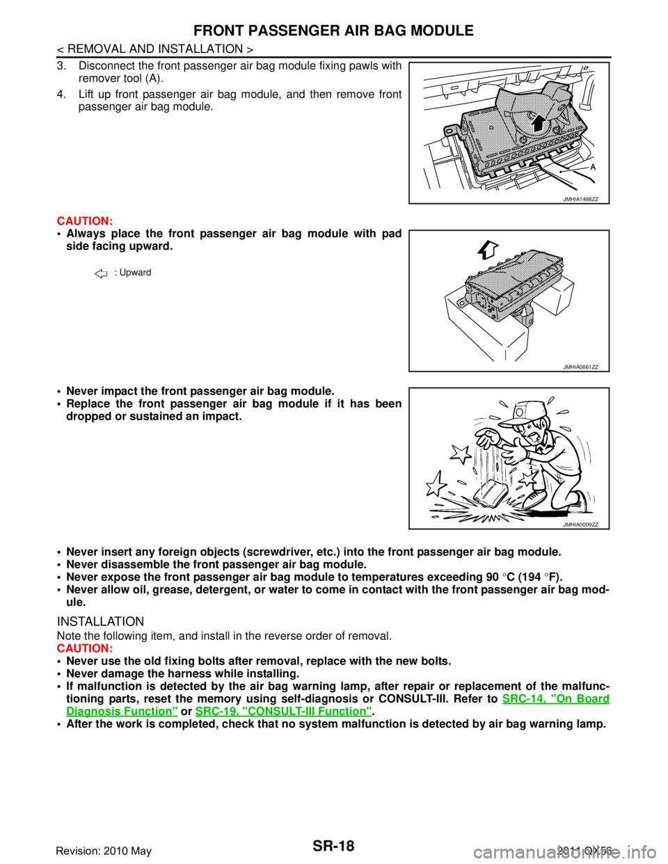
3. Disconnect the front passenger air bag module fixing pawls withremover tool (A).
4. Lift up front passenger air bag module, and then remove front passenger air bag module.
CAUTION:
Always place the front passenger air bag module with pad side facing upward.
Never impact the front passenger air bag module.
Replace the front passenger air bag module if it has been dropped or sustained an impact.
Never insert any foreign objects (screwdriver, etc.) into the front passenger air bag module.
Never disassemble the front passenger air bag module.
Never expose the front passenger air bag module to temperatures exceeding 90 °C (194 °F).
Never allow oil, grease, detergent, or water to co me in contact with the front passenger air bag mod-
ule.
INSTALLATION
Note the following item, and install in the reverse order of removal.
CAUTION:
Never use the old fixing bolts afte r removal, replace with the new bolts.
Never damage the harness while installing.
If malfunction is detected by the air bag warnin g lamp, after repair or replacement of the malfunc-
tioning parts, reset the memory using sel f-diagnosis or CONSULT-III. Refer to SRC-14, "
On Board
Diagnosis Function" or SRC-19, "CONSULT-III Function".
After the work is completed, check that no system malfunction is detected by air bag warning lamp.
JMHIA1488ZZ
: Upward
JMHIA0661ZZ
JMHIA0009ZZ
Revision: 2010 May2011 QX56
Page 4784 of 5598
SIDE CURTAIN AIR BAG MODULESR-21
< REMOVAL AND INSTALLATION >
C
DE
F
G
I
J
K L
M A
B
SR
N
O P
Never damage the harness while installing.
If malfunction is detected by the air bag warnin g lamp, after repair or replacement of the malfunc-
tioning parts, reset the memory using sel f-diagnosis or CONSULT-III. Refer to SRC-14, "
On Board
Diagnosis Function" or SRC-19, "CONSULT-III Function".
After the work is completed, check that no system malfunction is detected by air bag warning lamp.
Revision: 2010 May2011 QX56
Page 4786 of 5598
CRASH ZONE SENSORSR-23
< REMOVAL AND INSTALLATION >
C
DE
F
G
I
J
K L
M A
B
SR
N
O P
Replace the crash zone sensor of deployed driver air bag and deployed front passenger air bag.
INSTALLATION
Note the following item, and install in the reverse order of removal.
CAUTION:
Never use the old fixing nut afte r removal, replace with the new nut.
Never damage the harness co nnector while installing.
If malfunction is detected by the air bag warnin g lamp, after repair or replacement of the malfunc-
tioning parts, reset the memory using sel f-diagnosis or CONSULT-III. Refer to SRC-14, "
On Board
Diagnosis Function" or SRC-19, "CONSULT-III Function".
After the work is completed, check that no system malfunction is detected by air bag warning lamp.
Revision: 2010 May2011 QX56
Page 4788 of 5598

SIDE AIR BAG (SATELLITE) SENSOR
SR-25
< REMOVAL AND INSTALLATION >
C
D E
F
G
I
J
K L
M A
B
SR
N
O P
2. Remove the front seat belt retractor. Refer to SB-6, "SEAT BELT RETRACTOR : Removal and Installa-
tion".
3. Remove the side air bag front (satellite) sensor RH fixing nut.
4. Disconnect the side air bag front (satellite) sens or RH harness connector, and then remove side air bag
front (satellite) sensor RH.
SIDE AIR BAG REAR (SATELLITE) SENSOR LH
1. Remove the luggage side lower finisher LH. Refer to INT-36, "LUGGAGE SIDE LOWER FINISHER :
Removal and Installation".
2. Remove the side air bag rear (satellite) sensor LH fixing nut.
3. Disconnect the side air bag rear (satellite) sensor LH harness connector, and then remove side air bag
rear (satellite) sensor LH.
SIDE AIR BAG REAR (SATELLITE) SENSOR RH
1. Remove the luggage side lower finisher RH. Refer to INT-36, "LUGGAGE SIDE LOWER FINISHER :
Removal and Installation".
2. Remove the shield bracket fixing screw, and then remove shield bracket.
3. Remove the side air bag rear (satellite) sensor RH fixing nut.
4. Disconnect the side air bag rear (satellite) sensor RH harness connector, and then remove side air bag rear (satellite) sensor RH.
CAUTION:
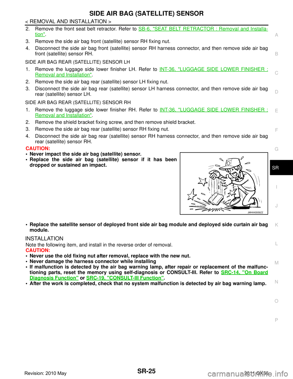
Never impact the side air bag (satellite) sensor.
Replace the side air bag (sat ellite) sensor if it has been
dropped or sustained an impact.
Replace the satellite sensor of deployed front side air bag module and deployed side curtain air bag
module.
INSTALLATION
Note the following item, and install in the reverse order of removal.
CAUTION:
Never use the old fixing nut afte r removal, replace with the new nut.
Never damage the harness connector while installing
If malfunction is detected by the air bag warnin g lamp, after repair or replacement of the malfunc-
tioning parts, reset the memory using sel f-diagnosis or CONSULT-III. Refer to SRC-14, "
On Board
Diagnosis Function" or SRC-19, "CONSULT-III Function".
After the work is completed, check that no system malfunction is detected by air bag warning lamp.
JMHIA0009ZZ
Revision: 2010 May2011 QX56