Page 1445 of 2057

firmly grasp the road wheel and apply a rocking
motion checking for any free play in the steering
linkage.
E56375
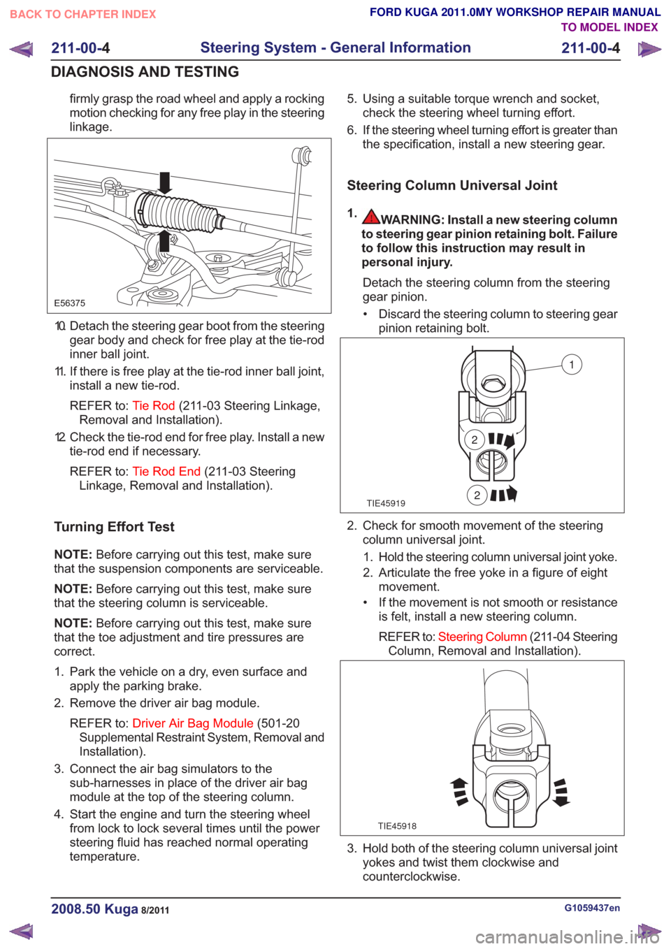
10. Detach the steering gear boot from the steeringgear body and check for free play at the tie-rod
inner ball joint.
11. If there is free play at the tie-rod inner ball joint, install a new tie-rod.
REFER to: Tie Rod(211-03 Steering Linkage,
Removal and Installation).
12. Check the tie-rod end for free play. Install a new tie-rod end if necessary.
REFER to: Tie Rod End (211-03 Steering
Linkage, Removal and Installation).
Turning Effort Test
NOTE: Before carrying out this test, make sure
that the suspension components are serviceable.
NOTE: Before carrying out this test, make sure
that the steering column is serviceable.
NOTE: Before carrying out this test, make sure
that the toe adjustment and tire pressures are
correct.
1. Park the vehicle on a dry, even surface and apply the parking brake.
2. Remove the driver air bag module.
REFER to: Driver Air Bag Module (501-20
Supplemental Restraint System, Removal and
Installation).
3. Connect the air bag simulators to the sub-harnesses in place of the driver air bag
module at the top of the steering column.
4. Start the engine and turn the steering wheel from lock to lock several times until the power
steering fluid has reached normal operating
temperature. 5. Using a suitable torque wrench and socket,
check the steering wheel turning effort.
6. If the steering wheel turning effort is greater than the specification, install a new steering gear.
Steering Column Universal Joint
1.WARNING: Install a new steering column
to steering gear pinion retaining bolt. Failure
to follow this instruction may result in
personal injury.
Detach the steering column from the steering
gear pinion.• Discard the steering column to steering gear pinion retaining bolt.
TIE45919
1
2
2
2. Check for smooth movement of the steeringcolumn universal joint.
1. Hold the steering column universal joint yoke.
2. Articulate the free yoke in a figure of eight movement.
• If the movement is not smooth or resistance is felt, install a new steering column.
REFER to: Steering Column (211-04 Steering
Column, Removal and Installation).
TIE45918
3. Hold both of the steering column universal joint yokes and twist them clockwise and
counterclockwise.
G1059437en2008.50 Kuga8/2011
211-00- 4
Steering System - General Information
211-00- 4
DIAGNOSIS AND TESTING
TO MODEL INDEX
BACK TO CHAPTER INDEX
FORD KUGA 2011.0MY WORKSHOP REPAIR MANUAL
Page 1449 of 2057

Power Steering System Flushing
MaterialsSpecification
Name
WSS-M2C204-A2 /
5U7J-M2C204-AA
Hydraulic Fluid DP-PS
1. WARNING: Be prepared to collect escaping fluids.
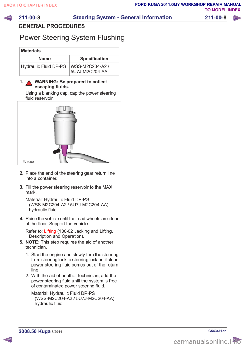
Using a blanking cap, cap the power steering
fluid reservoir.
E74090
2.Place the end of the steering gear return line
into a container.
3. Fill the power steering reservoir to the MAX
mark.
Material: Hydraulic Fluid DP-PS
(WSS-M2C204-A2 / 5U7J-M2C204-AA)
hydraulic fluid
4. Raise the vehicle until the road wheels are clear
of the floor. Support the vehicle.
Refer to: Lifting(100-02 Jacking and Lifting,
Description and Operation).
5. NOTE: This step requires the aid of another
technician.
1. Start the engine and slowly turn the steering from steering lock to steering lock until clean
power steering fluid comes out of the return
line.
2. With the aid of another technician, add the power steering fluid until the system is free
of contaminated power steering fluid.
Material: Hydraulic Fluid DP-PS(WSS-M2C204-A2 / 5U7J-M2C204-AA)
hydraulic fluid
G543411en2008.50 Kuga8/2011
211-00- 8
Steering System - General Information
211-00- 8
GENERAL PROCEDURES
TO MODEL INDEX
BACK TO CHAPTER INDEX
FORD KUGA 2011.0MY WORKSHOP REPAIR MANUAL
Page 1470 of 2057
Power Steering Pressure Line and Return Line Assembly — 2.5LDuratec (147kW/200PS) - VI5(13 443 0)
General Equipment
Hose Clamp Remover/Installer
Removal
NOTE: Removal steps in this procedure may
contain installation details.
1. Refer to: Steering System Health and Safety
Precautions (100-00 General Information,
Description and Operation).
2. Refer to: Wheel and Tire (204-04 Wheels and
Tires, Removal and Installation).
3.
E98543
x7
4.
E99630
5.
E99631
6. WARNING: Be prepared to collect escaping fluid.
1. General Equipment: Hose ClampRemover/Installer
2. Torque: 30
Nm
E114706
1
2
7. Torque: 23Nm1.
2. Torque: 7
Nm
G1185534en2008.50 Kuga8/2011
211-02- 13
Power Steering
211-02- 13
REMOVAL AND INSTALLATION
TO MODEL INDEX
BACK TO CHAPTER INDEX
FORD KUGA 2011.0MY WORKSHOP REPAIR MANUAL
Page 1471 of 2057
E112634
2
1
8.Torque: 4Nm
E99258
9. WARNING: Be prepared to collect
escaping fluid.
CAUTION: Make sure that all openings
are sealed.
Torque: 18
Nm
E114705
10.
G1185534en2008.50 Kuga8/2011
211-02- 14
Power Steering
211-02- 14
REMOVAL AND INSTALLATION
TO MODEL INDEX
BACK TO CHAPTER INDEX
FORD KUGA 2011.0MY WORKSHOP REPAIR MANUAL
Page 1475 of 2057
Power Steering Pump — 2.5L Duratec (147kW/200PS) -VI5(13 434 0)
General Equipment
Hose Clamp(s)
Hose Clamp Remover/Installer
Removal
NOTE: Removal steps in this procedure may
contain installation details.
1. Refer to: Steering System Health and Safety
Precautions (100-00 General Information,
Description and Operation).
2. Refer to: Wheel and Tire (204-04 Wheels and
Tires, Removal and Installation).
3.
E98543
x7
4.
E99630
5.
E99631
6. 1. WARNING: Be prepared to collect
escaping fluid.
General Equipment: Hose Clamp(s)
2. General Equipment: Hose Clamp Remover/Installer
E114163
12
7.1. WARNING: Be prepared to collect
escaping fluid.
Torque: 30Nm
3. General Equipment: Hose Clamp
Remover/Installer
4. Torque: 10
Nm
G1176952en2008.50 Kuga8/2011
211-02- 18
Power Steering
211-02- 18
REMOVAL AND INSTALLATION
TO MODEL INDEX
BACK TO CHAPTER INDEX
FORD KUGA 2011.0MY WORKSHOP REPAIR MANUAL
Page 1478 of 2057
Power Steering Pump to Steering Gear Pressure Line — 2.5LDuratec (147kW/200PS) - VI5(13 440 0; 13 443 0)
General Equipment
Hose Clamp Remover/Installer
Removal
NOTE: Removal steps in this procedure may
contain installation details.
1. Refer to: Steering System Health and Safety
Precautions (100-00 General Information,
Description and Operation).
2. Refer to: Wheel and Tire (204-04 Wheels and
Tires, Removal and Installation).
3.
E98543
x7
4.
E99630
5.
E99631
6. WARNING: Be prepared to collect escaping fluid.
1. General Equipment: Hose ClampRemover/Installer
2. Torque: 30
Nm
E114706
1
2
7. Torque: 23Nm1.
2. Torque: 7
Nm
G1185535en2008.50 Kuga8/2011
211-02- 21
Power Steering
211-02- 21
REMOVAL AND INSTALLATION
TO MODEL INDEX
BACK TO CHAPTER INDEX
FORD KUGA 2011.0MY WORKSHOP REPAIR MANUAL
Page 1479 of 2057
E112634
2
1
8.Torque: 4Nm
E99258
9. WARNING: Be prepared to collect
escaping fluid.
CAUTION: Make sure that all openings
are sealed.
Torque: 18
Nm
E114705
10.
G1185535en2008.50 Kuga8/2011
211-02- 22
Power Steering
211-02- 22
REMOVAL AND INSTALLATION
TO MODEL INDEX
BACK TO CHAPTER INDEX
FORD KUGA 2011.0MY WORKSHOP REPAIR MANUAL
Page 1484 of 2057
E99054
13.Torque: 4Nm
E99258
14. WARNING: Be prepared to collect
escaping fluid.
CAUTION: Make sure that all openings
are sealed.
Torque: 20
Nm
E99257
15.
G1001271en2008.50 Kuga8/2011
211-02- 27
Power Steering
211-02- 27
REMOVAL AND INSTALLATION
TO MODEL INDEX
BACK TO CHAPTER INDEX
FORD KUGA 2011.0MY WORKSHOP REPAIR MANUAL