2011 FORD KUGA start button
[x] Cancel search: start buttonPage 290 of 2057

Cellular Phone
Refer to
Wiring Diagrams Section 415-00, for
schematic and connector information. General Equipment
Ford diagnostic equipment
Principles of Operation
NOTE: Voice control will only operate with the
audio unit and components required switched ON.
Voice Control
The portable support electronics (PSE) module
has a voice control system. The customer will be
able to push the VOICE button on the audio control
switch located on the steering column lower
shroud, this will activate the PSE module and allow
voice control. An audible tone will be heard through
the audio unit speakers after which, a voice
command can then be spoken into the microphone
located in the overhead console.
The incoming calls and voice confirmation can be
heard through the audio system speakers.
When a voice command is spoken into the
microphone it will be sent as a signal to the PSE
module. The signal is then sent from the PSE
module to the relevant components on the
medium-speed controller area network (CAN) bus
network. The component will then convert the
signal back into the original voice command.
The components that the PSE module interacts
with are as follows:
• audio unit
• navigation system display module
• cellular phone
For additional information on the cellular phone
system, REFER to the cellular phone Owner's
Guide.
Bluetooth
An input can be given through the cellular phone
with or without the cellular phone connected to the
handset holder. Providing that the cellular phone
is one of the recommended cellular phones for the
system, is supplied with the Bluetooth technology
and the cellular phone is programmed to the PSE
module.
When selected as active the Bluetooth technology
is a wireless system that interacts with the relevant component modules through the PSE module. The
general operation of the Bluetooth is similar to the
voice control.
Bluetooth technology cannot transfer the cellular
phone's PHONEBOOK or recent outgoing and
incoming call details to the audio unit or navigation
system display module. If the cellular phone is
placed into the handset holder the PHONEBOOK
data and recent outgoing and incoming call
information will be transferred to the audio unit or
navigation system display module.
For additional information, REFER to the cellular
phone Owner's Guide.
Inspection and Verification
NOTE: Make sure that the cellular phone is
featured on the list of recommended cellular
phones for the system.
Make sure that the PSE module and cellular
phone are configured to each other before
starting a system diagnosis. ENTER the
following PIN number on the cellular phone to
configure the cellular phone to the PSE module:
0000.
Make sure that the MUTE symbol is not
displayed on the audio unit when trying to
operate the cellular phone system. If the MUTE
symbol is displayed, this indicates that the PSE
module requires configuring to the vehicle and
the cellular phone requires programming to the
PSE module. GO to
Pinpoint Test C.
1. Verify the customer concern by operating the system using the customers cellular phone.
2. Visually inspect for obvious signs of electrical damage.
Visual Inspection Chart Electrical
• Fuse(s)
• Wiring harness
• Electrical connector(s)
• Cellular phone
• Microphone
• PSE module
• Audio unit
• Instrument cluster
• Navigation system display module G1189085en
2008.50 Kuga 8/2011 415-00-4
Information and Entertainment System -
General Information
415-00-4
DIAGNOSIS AND TESTINGTO MODEL INDEX
BACK TO CHAPTER INDEX
FORD KUGA 2011.0MY WORKSHOP REPAIR MANUAL
Page 306 of 2057

• Volume adjustment
– To increase the volume, press the top rearbutton on the remote control.
– To lower the volume: Press the bottom rear button on the remote control.
• Search – During radio operation, the station search isstarted upwards or downwards within the
frequency band.
– During CD operation, this skips to the next or previous track.
• Mode –During radio operation, the next saved station
is called up (if pressed briefly).
– During radio operation, to switch wave range
(if pressed and held).
– During CD operation, provided a CD changer
is installed, the next CD is played.
Antenna systems
The antenna systems fitted to the vehicle comprise:
• AM/FM roof antennal
• AM/FM/GPS roof antenna
• Roof antenna for digital radio system (vehicles with DAB radio) G1055647en
2008.50 Kuga 8/2011 415-01-10
Information and Entertainment System
415-01-10
DESCRIPTION AND OPERATIONTO MODEL INDEX
BACK TO CHAPTER INDEX
FORD KUGA 2011.0MY WORKSHOP REPAIR MANUAL
Page 447 of 2057

Anti-Theft - Passive – System Operation and Component
Description
System DiagramTO MODEL INDEX
BACK TO CHAPTER INDEX
FORD KUGA 2011.0MY WORKSHOP REPAIR MANUAL 419-01B-4
Anti-Theft - Passive
419-01B-4
DESCRIPTION AND OPERATION Description
Item
Keyless vehicle module (KVM)Refer to Component Description: (page
?)
1
Start/stop button
2 Description
Item
Interior antennasRefer to Component Description: (page
?)
3 G1065785en
2008.50 Kuga 8/2011
Page 448 of 2057

Description
Item
Passive key (radio remote control with
integrated emergency key)Refer to Component Description: (page
?)
4
RF receiverRefer to Component Description: (page
?)
5
PCM6 Description
Item
Transceiver of passive anti-theft system
(emergency start function)Refer to Component Description: (page
?)
7
Instrument clusterRefer to Component Description: (page
?)
8
System Operation
Passive Anti-theft System
The passive anti-theft system PATS (passive
anti-theft system) is based on an electronic engine
immobiliser.
The driver does not need to intervene in any way
to protect the vehicle, since PATS is automatically
activated when the ignition is switched off.
Component Description
Keyless vehicle module (KVM) The PATS functionality is saved in the KVM. After
pressing the start/stop button, the KVM activates
the interior antennas, which then transmit a signal.
If there is a valid passive key in the vehicle interior,
it sends an encrypted signal to the radio frequency
receiver. The radio receiver forwards this signal to
the KVM via a fixed wire. The KVM then forwards
a corresponding identification query via the HS
CAN (controller area network) to the PCM.
If a valid code was received to this query, then the
engine can be started. Interior antennas
The four interior antennas transmit an LF signal
which is identified by the passive key.
Passive key (radio remote control with
integrated emergency key)
G1065785en
2008.50 Kuga 8/2011 419-01B-5
Anti-Theft - Passive
419-01B-5
DESCRIPTION AND OPERATIONTO MODEL INDEX
BACK TO CHAPTER INDEX
FORD KUGA 2011.0MY WORKSHOP REPAIR MANUALE100587 E100793 E87065132
Page 459 of 2057

• 4 minutes have elapsed since the button for the
heated windshield was pressed.
• The ignition switch is turned to the "I" or "0" position.
• The "Defrost" function is deactivated or the switch for the heated windscreen is pressed
again while the heated windscreen is still
switched on.
• The charging system warning indicator is switched on.
• The battery voltage falls below the threshold value for low battery voltage for more than 20
seconds (power management strategy). Manual
requests for switching on the heated windshield
by pressing the switch are ignored at this time.
• More than 4 minutes have passed since starting
the engine.
Heated rear window and heated external
mirrors
The GEM transmits a request signal via the CAN
bus to the door modules to switch on the heated
exterior mirrors.
The heated rear window and the heated exterior
mirrors are switched on by the GEM under the
following conditions:
• The switch for the heated rear window is pressed and the ignition switch is in the "II"
position.
• The "defrost" function of the air conditioning is activated and the ignition switch is in the position
"II".
• The battery voltage has exceeded 16 V for more
than 20 seconds (power management strategy).
Manual requests to switch off the heated rear
window by pressing the button are ignored at
this time.
• The engine was started at an outside air temperature below 4°C and an engine
temperature below 65°. Manual requests for
switching off the heated rear window by pressing
the switch are accepted.
NOTE: If the battery voltage returns to the normal
range then the disabling of the heated rear window
is cancelled - the heated rear window is then in a
switched-off state.
The GEM transmits a request signal via the CAN
bus to the door modules to switch off the heated
exterior mirrors. The heated rear window and the heated exterior
mirrors are switched off by the GEM under the
following conditions
• 14 minutes have elapsed since the button for
the heated rear window was pressed.
• The ignition switch is turned to the position "0", "I" or "III".
• The switch for the heated rear window is pressed or the "defrost" function of the air
conditioning is deactivated while the heated rear
window is switched on.
• The battery voltage has dropped below 10.3 V for more than 20 seconds (power management
strategy). Manual requests for switching on the
heated rear window by pressing the switch are
ignored at this time.
• More than 14 minutes have passed since starting the engine.
Ambient air temperature
The ambient air temperature sensor is connected
via a cable to the GEM. It measures the outside
air temperature to an accuracy of around ±0.5 °C.
The GEM broadcasts the ambient air temperature
on the medium speed CAN bus, where it can be
evaluated by various systems.
Brake fluid level
The brake fluid level switch is connected via a
cable to the GEM.
The GEM transmits a message on the medium
speed CAN bus. The instrument cluster then
transfers this message to the high speed CAN bus
where it is made available for various other
functions.
Automatic headlamps
Refer to: Exterior Lighting (417-01 Exterior Lighting,
Description and Operation).
Combined rain sensor/light sensor
Refer to: Exterior Lighting (417-01 Exterior Lighting,
Description and Operation). G1030788en
2008.50 Kuga 8/2011 419-10-9
Multifunction Electronic Modules
419-10-9
DESCRIPTION AND OPERATIONTO MODEL INDEX
BACK TO CHAPTER INDEX
FORD KUGA 2011.0MY WORKSHOP REPAIR MANUAL
Page 1750 of 2057

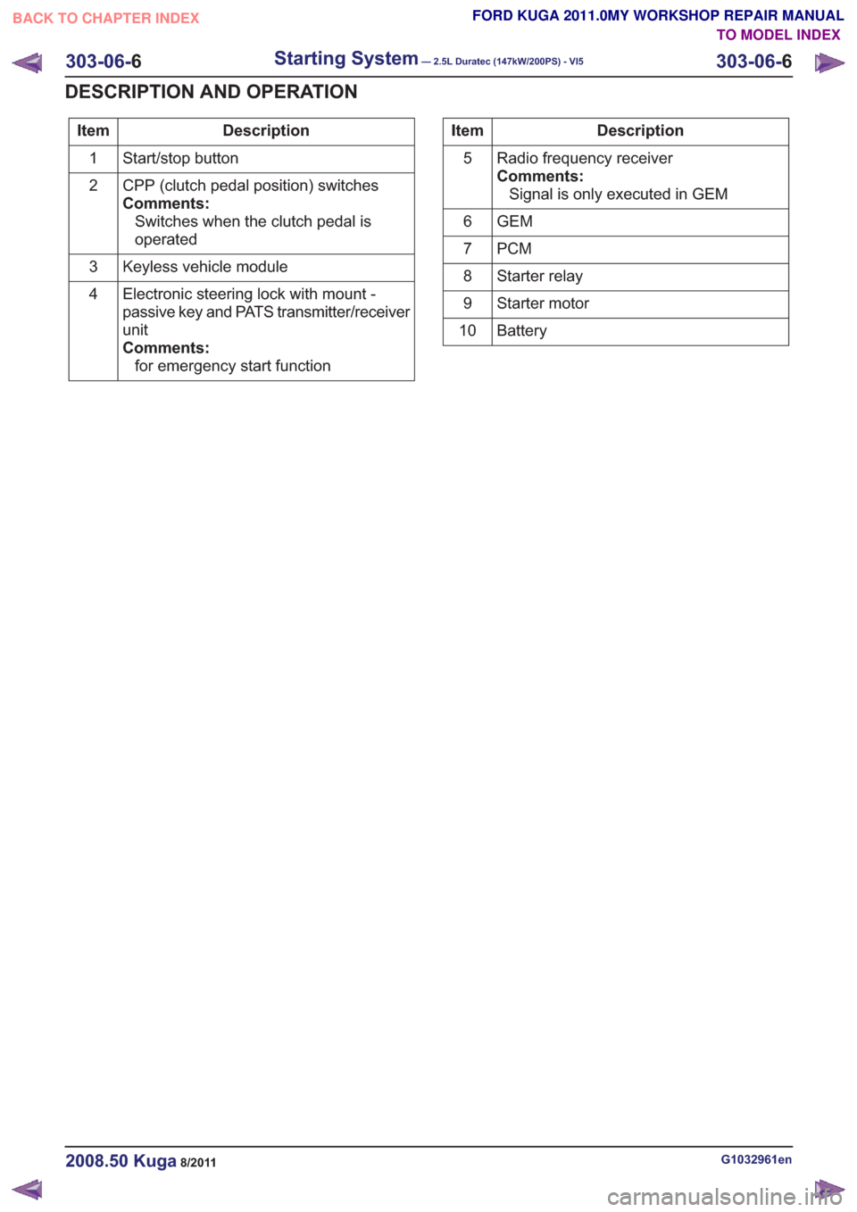
Description
Item
Start/stop button
1
CPP (clutch pedal position) switches
Comments:Switches when the clutch pedal is
operated
2
Keyless vehicle module
3
Electronic steering lock with mount -
passive key and PATS transmitter/receiver
unit
Comments:for emergency start function
4Description
Item
Radio frequency receiver
Comments:Signal is only executed in GEM
5
GEM
6
PCM
7
Starter relay
8
Starter motor
9
Battery
10
G1032961en2008.50 Kuga8/2011
303-06- 6
Starting System— 2.5L Duratec (147kW/200PS) - VI5303-06-
6
DESCRIPTION AND OPERATION
TO MODEL INDEX
BACK TO CHAPTER INDEX
FORD KUGA 2011.0MY WORKSHOP REPAIR MANUAL
Page 1752 of 2057

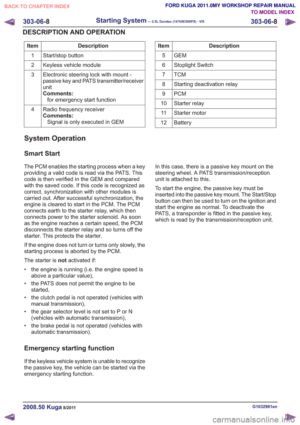
Description
Item
Start/stop button
1
Keyless vehicle module
2
Electronic steering lock with mount -
passive key and PATS transmitter/receiver
unit
Comments:for emergency start function
3
Radio frequency receiver
Comments:Signal is only executed in GEM
4Description
Item
GEM
5
Stoplight Switch
6
TCM7
Starting deactivation relay
8
PCM
9
Starter relay
10
Starter motor
11
Battery
12
System Operation
Smart Start
The PCM enables the starting process when a key
providing a valid code is read via the PATS. This
code is then verified in the GEM and compared
with the saved code. If this code is recognized as
correct, synchronization with other modules is
carried out. After successful synchronization, the
engine is cleared to start in the PCM. The PCM
connects earth to the starter relay, which then
connects power to the starter solenoid. As soon
as the engine reaches a certain speed, the PCM
disconnects the starter relay and so turns off the
starter. This protects the starter.
If the engine does not turn or turns only slowly, the
starting process is aborted by the PCM.
The starter is notactivated if:
• the engine is running (i.e. the engine speed is above a particular value),
• the PATS does not permit the engine to be started,
• the clutch pedal is not operated (vehicles with manual transmission),
• the gear selector level is not set to P or N (vehicles with automatic transmission),
• the brake pedal is not operated (vehicles with automatic transmission).
Emergency starting function
If the keyless vehicle system is unable to recognize
the passive key, the vehicle can be started via the
emergency starting function. In this case, there is a passive key mount on the
steering wheel. A PATS transmission/reception
unit is attached to this.
To start the engine, the passive key must be
inserted into the passive key mount. The Start/Stop
button can then be used to turn on the ignition and
start the engine as normal. To deactivate the
PATS, a transponder is fitted in the passive key,
which is read by the transmission/reception unit.
G1032961en2008.50 Kuga8/2011
303-06-
8
Starting System— 2.5L Duratec (147kW/200PS) - VI5303-06-
8
DESCRIPTION AND OPERATION
TO MODEL INDEX
BACK TO CHAPTER INDEX
FORD KUGA 2011.0MY WORKSHOP REPAIR MANUAL
Page 1865 of 2057

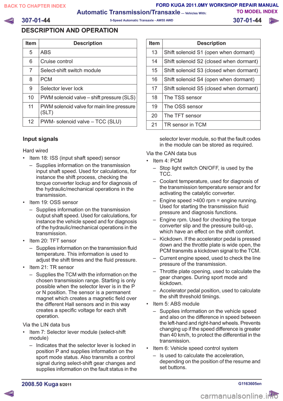
Description
Item
ABS5
Cruise control
6
Select-shift switch module
7
PCM
8
Selector lever lock
9
PWM solenoid valve – shift pressure (SLS)
10
PWM solenoid valve for main line pressure
(SLT)
11
PWM- solenoid valve – TCC (SLU)
12Description
Item
Shift solenoid S1 (open when dormant)
13
Shift solenoid S2 (closed when dormant)
14
Shift solenoid S3 (closed when dormant)
15
Shift solenoid S4 (open when dormant)
16
Shift solenoid S5 (closed when dormant)
17
The TSS sensor
18
The OSS sensor
19
The TFT sensor
20
TR sensor in TCM
21
Input signals
Hard wired
• Item 18: ISS (input shaft speed) sensor
– Supplies information on the transmissioninput shaft speed. Used for calculations, for
instance the shift process, checking the
torque converter lockup and for diagnosis of
the hydraulic/mechanical operations in the
transmission.
• Item 19: OSS sensor – Supplies information on the transmissionoutput shaft speed. Used for calculations, for
instance the vehicle speed and for diagnosis
of the hydraulic/mechanical operations in the
transmission.
• Item 20: TFT sensor – Supplies information on the transmission fluidtemperature. This information is used to
adjust the shift times and the fluid pressure.
• Item 21: TR sensor – Supplies the TCM with the information on thechosen transmission range. Starting is only
possible when the selector lever is in the P
or N position. The sensor is a permanent
magnet which creates a magnetic field over
the different Hall sensors and in this way
creates a specific voltage for each shift
operation.
Via the LIN data bus
• Item 7: Selector lever module (select-shift module)
– Indicates that the selector lever is locked inposition P and supplies information on the
sport mode status. Also transmits a control
signal during select-shift gear changes and
supplies information on the fault status in the selector lever module, so that the fault codes
in the module can be stored as required.
Via the CAN data bus
• Item 4: PCM – Stop light switch ON/OFF, is used by theTCC.
– Coolant temperature, used for diagnosis of the transmission temperature sensor and for
activating the catalytic converter.
– Engine speed >400 rpm = engine running. Used for starting the transmission fluid
pressure and diagnosis functions.
– Engine rpm. Used for checking the torque converter slip and the pressure build-up,
which have an effect on the shift comfort.
– Kickdown. If the accelerator pedal is pressed down and the throttle plate is wide open, the
PCM transmits a kickdown signal to the TCM.
– Current engine speed, used to check the line pressure of the transmission.
– Throttle plate opening, used to calculate the gear changes. During sport mode and
kickdown.
– Accelerator pedal position, used to calculate the shift threshold timings.
• Item 5: ABS module – Supplies information on the vehicle speedand also on the difference in speed between
the left-hand and right-hand wheels. Prevents
changing up if the speed difference is greater
than 40 km/h, to protect the differential in the
transmission.
• Item 6: Vehicle speed control system – Is used to calculate the acceleration,depending on the position of the resume and
set buttons.
G1163605en2008.50 Kuga8/2011
307-01- 44
Automatic Transmission/Transaxle
— Vehicles With:
5-Speed Automatic Transaxle - AW55 AWD
307-01- 44
DESCRIPTION AND OPERATION
TO MODEL INDEX
BACK TO CHAPTER INDEX
FORD KUGA 2011.0MY WORKSHOP REPAIR MANUAL