Page 1518 of 2057

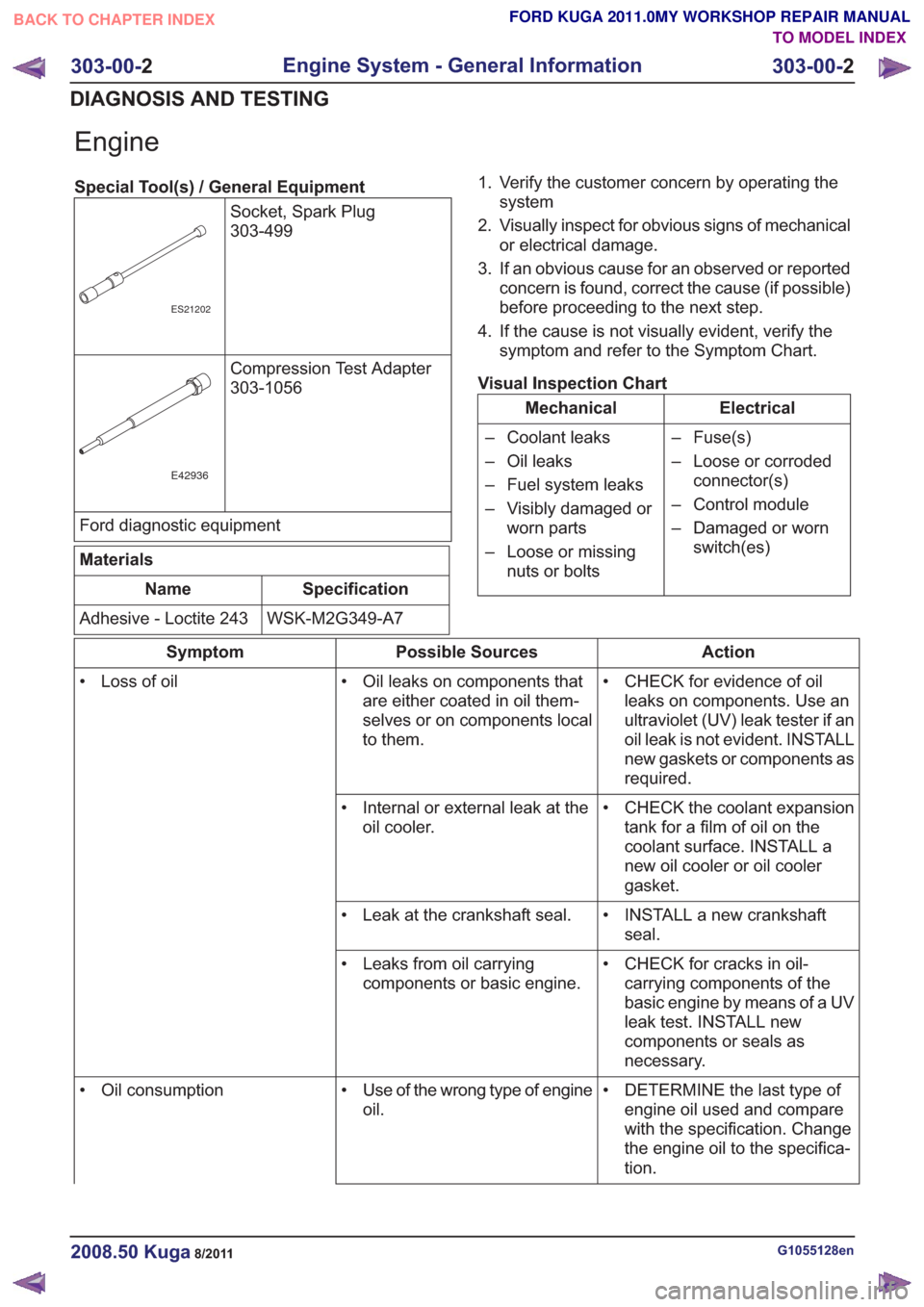
Engine
Special Tool(s) / General EquipmentSocket, Spark Plug
303-499
ES21202
Compression Test Adapter
303-1056
E42936
Ford diagnostic equipment
Materials
Specification
Name
WSK-M2G349-A7
Adhesive - Loctite 243 1. Verify the customer concern by operating the
system
2. Visually inspect for obvious signs of mechanical or electrical damage.
3. If an obvious cause for an observed or reported concern is found, correct the cause (if possible)
before proceeding to the next step.
4. If the cause is not visually evident, verify the symptom and refer to the Symptom Chart.
Visual Inspection Chart
Electrical
Mechanical
– Fuse(s)
– Loose or corrodedconnector(s)
– Control module
– Damaged or worn switch(es)
– Coolant leaks
– Oil leaks
– Fuel system leaks
– Visibly damaged or
worn parts
– Loose or missing nuts or bolts
Action
Possible Sources
Symptom
• CHECK for evidence of oilleaks on components. Use an
ultraviolet (UV) leak tester if an
oil leak is not evident. INSTALL
new gaskets or components as
required.
• Oil leaks on components that
are either coated in oil them-
selves or on components local
to them.
• Loss of oil
• CHECK the coolant expansiontank for a film of oil on the
coolant surface. INSTALL a
new oil cooler or oil cooler
gasket.
• Internal or external leak at the
oil cooler.
• INSTALL a new crankshaftseal.
• Leak at the crankshaft seal.
• CHECK for cracks in oil-carrying components of the
basic engine by means of a UV
leak test. INSTALL new
components or seals as
necessary.
• Leaks from oil carrying
components or basic engine.
• DETERMINE the last type ofengine oil used and compare
with the specification. Change
the engine oil to the specifica-
tion.
• Use of the wrong type of engine
oil.
• Oil consumption
G1055128en2008.50 Kuga8/2011
303-00-
2
Engine System - General Information
303-00- 2
DIAGNOSIS AND TESTING
TO MODEL INDEX
BACK TO CHAPTER INDEX
FORD KUGA 2011.0MY WORKSHOP REPAIR MANUAL
Page 1675 of 2057

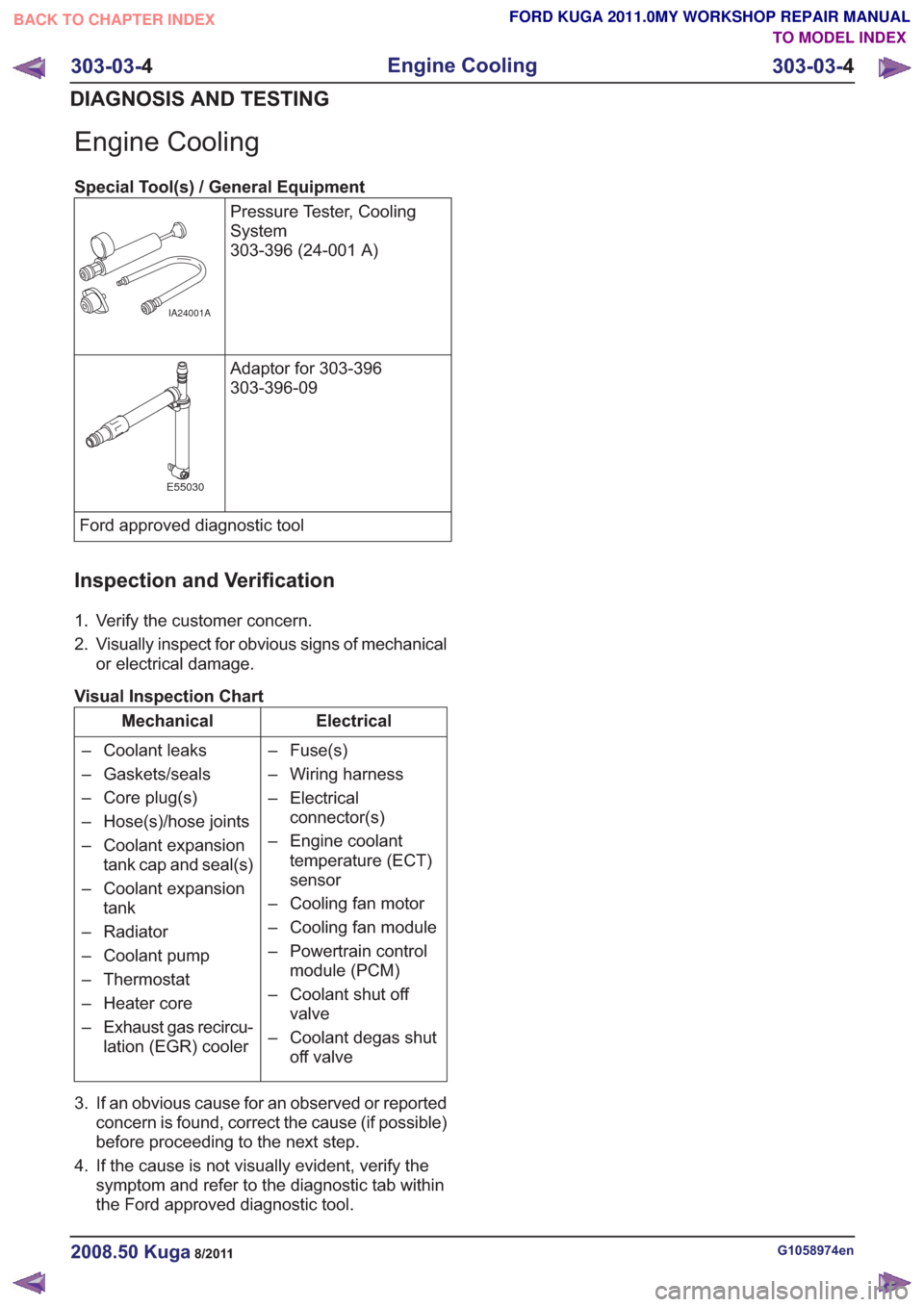
Engine Cooling
Special Tool(s) / General EquipmentPressure Tester, Cooling
System
303-396 (24-001 A)
IA24001A
Adaptor for 303-396
303-396-09
E55030
Ford approved diagnostic tool
Inspection and Verification
1. Verify the customer concern.
2. Visually inspect for obvious signs of mechanicalor electrical damage.
Visual Inspection Chart
Electrical
Mechanical
– Fuse(s)
– Wiring harness
– Electricalconnector(s)
– Engine coolant temperature (ECT)
sensor
– Cooling fan motor
– Cooling fan module
– Powertrain control module (PCM)
– Coolant shut off valve
– Coolant degas shut off valve
– Coolant leaks
– Gaskets/seals
– Core plug(s)
– Hose(s)/hose joints
– Coolant expansion
tank cap and seal(s)
– Coolant expansion tank
– Radiator
– Coolant pump
– Thermostat
– Heater core
– Exhaust gas recircu- lation (EGR) cooler
3. If an obvious cause for an observed or reported concern is found, correct the cause (if possible)
before proceeding to the next step.
4. If the cause is not visually evident, verify the symptom and refer to the diagnostic tab within
the Ford approved diagnostic tool.
G1058974en2008.50 Kuga8/2011
303-03- 4
Engine Cooling
303-03- 4
DIAGNOSIS AND TESTING
TO MODEL INDEX
BACK TO CHAPTER INDEX
FORD KUGA 2011.0MY WORKSHOP REPAIR MANUAL
Page 1676 of 2057

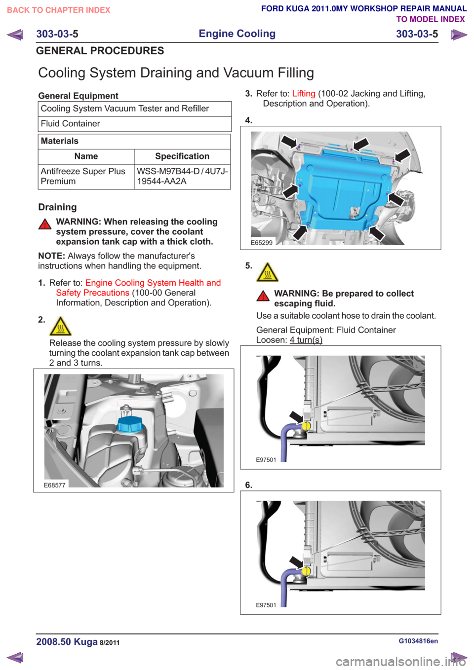
Cooling System Draining and Vacuum Filling
General EquipmentCooling System Vacuum Tester and Refiller
Fluid Container
Materials
Specification
Name
WSS-M97B44-D / 4U7J-
19544-AA2A
Antifreeze Super Plus
Premium
Draining
WARNING: When releasing the cooling
system pressure, cover the coolant
expansion tank cap with a thick cloth.
NOTE: Always follow the manufacturer's
instructions when handling the equipment.
1. Refer to: Engine Cooling System Health and
Safety Precautions (100-00 General
Information, Description and Operation).
2.
Release the cooling system pressure by slowly
turning the coolant expansion tank cap between
2 and 3 turns.
E68577
3. Refer to: Lifting(100-02 Jacking and Lifting,
Description and Operation).
4.
E65299
5.
WARNING: Be prepared to collect
escaping fluid.
Use a suitable coolant hose to drain the coolant.
General Equipment: Fluid Container
Loosen: 4
turn(s)
E97501
6.
E97501
G1034816en2008.50 Kuga8/2011
303-03- 5
Engine Cooling
303-03- 5
GENERAL PROCEDURES
TO MODEL INDEX
BACK TO CHAPTER INDEX
FORD KUGA 2011.0MY WORKSHOP REPAIR MANUAL
Page 1677 of 2057

7.
E65299
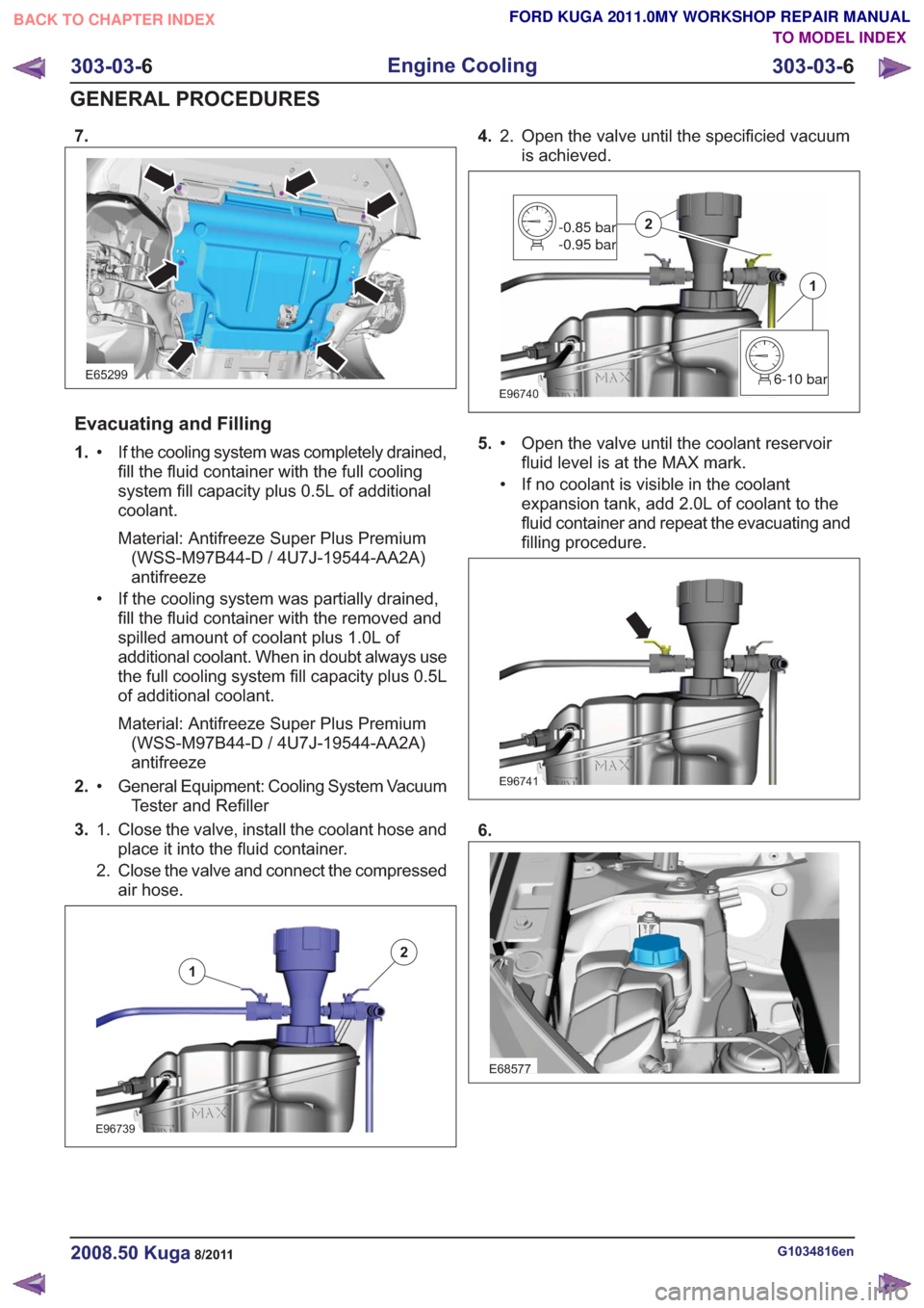
Evacuating and Filling
1.If the cooling system was completely drained,
fill the fluid container with the full cooling
•
system fill capacity plus 0.5L of additional
coolant.
Material: Antifreeze Super Plus Premium(WSS-M97B44-D / 4U7J-19544-AA2A)
antifreeze
• If the cooling system was partially drained, fill the fluid container with the removed and
spilled amount of coolant plus 1.0L of
additional coolant. When in doubt always use
the full cooling system fill capacity plus 0.5L
of additional coolant.
Material: Antifreeze Super Plus Premium(WSS-M97B44-D / 4U7J-19544-AA2A)
antifreeze
2. General Equipment: Cooling System Vacuum
Tester and Refiller
•
3. Close the valve, install the coolant hose and
place it into the fluid container.
1.
2. Close the valve and connect the compressed
air hose.
E96739
1
2
4. Open the valve until the specificied vacuum
is achieved.
2.
E967406-10 bar
1
-0.85 bar
-0.95 bar2
5.
Open the valve until the coolant reservoir
fluid level is at the MAX mark.
•
• If no coolant is visible in the coolant
expansion tank, add 2.0L of coolant to the
fluid container and repeat the evacuating and
filling procedure.
E96741
6.
E68577
G1034816en2008.50 Kuga8/2011
303-03- 6
Engine Cooling
303-03- 6
GENERAL PROCEDURES
TO MODEL INDEX
BACK TO CHAPTER INDEX
FORD KUGA 2011.0MY WORKSHOP REPAIR MANUAL