2011 FORD KUGA brakes
[x] Cancel search: brakesPage 63 of 2057

Road/Roller Testing
Road or roller testing may be carried out for various
reasons and a procedure detailing pre-test checks,
engine starting and stopping, pre-driving checks,
on-test checks and final checks to be completed
on completion of the test is given below.
Unless complete vehicle performance is being
checked, the full road test procedure need not be
carried out. Instead, those items particularly
relevant to the system(s) being checked can be
extracted.
Pre-Test Checks
WARNING: If the brake system hydraulic
fluid level is low, pedal travel is excessive
or a hydraulic leak is found, do not attempt
to road test the vehicle until the reason for
the low fluid level, excessive pedal travel
or hydraulic leak is found and rectified.
It is suggested that pre-test checks and functional
tests of those systems and circuits which affect the
safe and legal operations of the vehicle, such as
brakes, lights and steering, should always be
carried out before the road or roller test.
With the ignition switched off, check:
– the engine oil level.
– the engine coolant level.
– the tires, for correct pressure, compatible types and tread patterns, and wear within limits.
– that there is sufficient fuel in the tank to complete the test.
– all around the engine, transmission and under the vehicle for oil, coolant, hydraulic and fuel
leaks. Make a note of any apparent leaks and
wipe off the surrounding areas to make it easier
to identify the extent of the leak on completion
of the test.
Starting the Engine
NOTE: On initial drive away from cold and within
the first 1.5 km (1 mile), do not depress the
accelerator pedal beyond half travel until the
vehicle has attained a minimum speed of 25 km/h
(15 miles/h). Never operate at high engine speed
or with the accelerator pedal at full travel whilst the
engine is cold.
With the ignition switched off, check: – that the parking brake is applied.
– that the gear lever is in the neutral position.
– that all instrument gauges (except fuel gauge)
read zero.
With the ignition switched on, check:
– that the ignition controlled warning lamps are illuminated.
– that the engine temperature gauge registers a reading compatible with the engine temperature.
– that the fuel gauge registers a reading appropriate to the fuel level in the tank.
– the operation of the parking brake warning lamp and fluid level warning indicator.
Road or Roller Testing
CAUTION: If road testing, check the brake
operation while still traveling at low speed
before continuing with the test. If the
brakes pull to one side, or appear to be
otherwise faulty, do not continue with the
road test until the fault has been found and
rectified.
During the road or roller test, check:
– that the clutch pedal operation is not stiff or heavy.
– that the initial gear engagement is smooth and there is no evidence of clutch drag.
– that the parking brake control operates smoothly and releases quickly and completely.
– that the clutch takes up the drive smoothly, without slip or judder.
– that gear changing is smooth with no abnormal noises or vibrations from the transmission.
– the engine power output is satisfactory, full power is achieved, acceleration is smooth and
pedal operation is not stiff or heavy, and engine
speed returns to idle correctly.
– there is no excessive or abnormally colored smoke from the engine under normal driving,
heavy load or overrun conditions.
– that steering operation, including power steering (if equipped), is smooth, accurate, not
excessively heavy or with excessive free play
or vibration.
– that the steering does not pull to one side and self centers smoothly after cornering.
G17375en2008.50 Kuga8/2011
100-00- 58
General Information
100-00- 58
DESCRIPTION AND OPERATION
TO MODEL INDEX
BACK TO CHAPTER INDEX
FORD KUGA 2011.0MY WORKSHOP REPAIR MANUAL
Page 64 of 2057

– that the speedometer, coolant temperaturegauge and tachometer (if equipped) register the
correct readings and operate correctly.
– that the switches and controls operate smoothly and positively, warning and indicator lamps
operate correctly and the direction indicator
control self cancels when the steering is
returned to the straight ahead position.
– that the heating and ventilation systems operate correctly and effectively.
– the brake operation and efficiency.
Brake Testing
WARNING: When brake testing, avoid
breathing the fumes from hot brakes, this
may contain asbestos dust which is
hazardous to health. Failure to follow this
instruction may result in personal injury.
For additional information, refer to: Health
and Safety Precautions (100-00 General
Information, Description and Operation).
CAUTIONS:
Avoid brake testing on busy roads where
it may cause inconvenience or danger to
other road users.
Brake testing which includes heavy brake
applications should not be carried out with
new brake pads/discs or linings/drums
until the components have bedded-in. New
brake friction components will not reach
full efficiency until the bedding-in process
is complete.
Test the brakes at several speeds within the normal
operating range using both light and heavy pedal
pressure. Note any tendency to snatch, pull or
drag, and any undue delay in application or
release.
Allow the vehicle to coast and note any tendency
to pull to one side, or evidence that the brakes are
binding.
After stopping the vehicle (not immediately after a
period of heavy braking), carefully check the brake
temperature. A brake disc or brake drum that feels
hot or is appreciably hotter than the others,
indicates that the brake is binding.
After completion of the test, check for: – oil, coolant, hydraulic, air and fuel leaks.
– abnormal temperature of any moving
components or assemblies, for example wheel
hubs, transmission and axle, which might
indicate over tightness or lack of lubrication.
G17375en2008.50 Kuga8/2011
100-00- 59
General Information
100-00- 59
DESCRIPTION AND OPERATION
TO MODEL INDEX
BACK TO CHAPTER INDEX
FORD KUGA 2011.0MY WORKSHOP REPAIR MANUAL
Page 82 of 2057

sometimes noticed in the steering wheel/column,
seats, front floor panel, front door trim panel or
front end sheet metal. It is a low frequency
vibration (around 9-15 cycles per second). It
may or may not be increased by applying the
brakes lightly. REFER to Idle
Boom/Shake/Vibration in the Driveline Noise
and Vibration Symptom Chart.
3. High Speed: A vibration is felt in the front floor panel or seats with no visible shake, but with
an accompanying sound or rumble, buzz, hum,
drone or booming noise. Coast with the clutch
pedal depressed (manual transmission) or shift
control selector lever in "N" (NEUTRAL)
(automatic transmission) and engine idling. If
vibration is still evident, it may be related to
wheels, tires, front brake discs, wheel hubs or
front wheel bearings. REFER to Shake and
Vibration While Driving in the Driveline Noise
and Vibration Symptom Chart.
4. Engine rpm Sensitive: A vibration is felt whenever the engine reaches a particular rpm.
It will disappear in neutral coasts. The vibration
can be duplicated by operating the engine at
the problem rpm while the vehicle is stationary.
It can be caused by any component, from the
accessory drive belt to the clutch or torque
converter which turns at engine speed when the
vehicle is stopped. REFER to Shake and
Vibration While Driving in the Driveline Noise
and Vibration Symptom Chart.
5. Noise and Vibration While Turning: Clicking, popping or grinding noises may be due to the
following:
• worn, damaged or incorrectly installed front wheel bearing.
• damaged powertrain/drivetrain mounts.
Road Conditions
An experienced technician will always establish a
route that will be used for all NVH diagnosis road
tests. The road selected should be reasonably
smooth, level and free of undulations (unless a
particular condition needs to be identified). A
smooth asphalt road that allows driving over a
range of speeds is best. Gravel or bumpy roads
are unsuitable because of the additional road noise
produced. Once the route is established and consistently used, the road noise variable is
eliminated from the test results.
NOTE:
Some concerns may be apparent only on
smooth asphalt roads.
If a customer complains of a noise or vibration on
a particular road and only on a particular road, the
source of the concern may be the road surface. If
possible, try to test the vehicle on the same type
of road.
Vehicle Preparation
Carry out a thorough visual inspection of the
vehicle before carrying out the road test. Note
anything which is unusual. Do not repair or adjust
any condition until the road test is carried out,
unless the vehicle is inoperative or the condition
could pose a hazard to the technician. After
verifying that the condition has been corrected,
make sure all components removed have been
installed.
Power Steering Conditions
Check for the noise in the following conditions to
verify the customer concern.
• Check for the noise in several temperature conditions.
• Is the noise from when the vehicle was new?
• Can the noise be repeated constantly or is it random?
• Check the condition of the vehicle age, mileage and service record.
• Interview the customer to find the operating condition in which the noise will occur. Test the
vehicle based on the detail(s) from the customer
interview.
• Follow the power steering operation noise condition tables below, to find which condition
the noise will occur.
Power Steering Operation Noise Check
Step 1: Check for NVH concerns from non-steering
components, which may sound like noises coming
from the steering system.
G37349en2008.50 Kuga8/2011
100-04- 4
Noise, Vibration and Harshness
100-04- 4
DIAGNOSIS AND TESTING
TO MODEL INDEX
BACK TO CHAPTER INDEX
FORD KUGA 2011.0MY WORKSHOP REPAIR MANUAL
Page 1298 of 2057
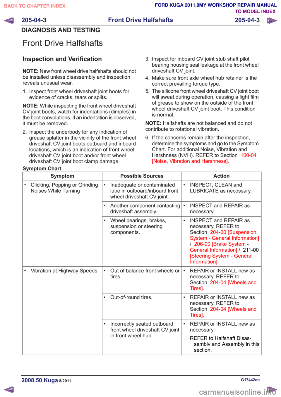
Front Drive Halfshafts
Inspection and Verification
NOTE:New front wheel drive halfshafts should not
be installed unless disassembly and inspection
reveals unusual wear.
1. Inspect front wheel driveshaft joint boots for evidence of cracks, tears or splits.
NOTE: While inspecting the front wheel driveshaft
CV joint boots, watch for indentations (dimples) in
the boot convolutions. If an indentation is observed,
it must be removed.
2. Inspect the underbody for any indication of grease splatter in the vicinity of the front wheel
driveshaft CV joint boots outboard and inboard
locations, which is an indication of front wheel
driveshaft CV joint boot and/or front wheel
driveshaft CV joint boot clamp damage. 3. Inspect for inboard CV joint stub shaft pilot
bearing housing seal leakage at the front wheel
driveshaft CV joint.
4. Make sure front axle wheel hub retainer is the correct prevailing torque type.
5. The silicone front wheel driveshaft CV joint boot will sweat during operation, causing a light film
of grease to show on the outside of the front
wheel driveshaft CV joint boot. This condition
is normal.
NOTE: Halfshafts are not balanced and do not
contribute to rotational vibration.
6. If the concerns remain after the inspection, determine the symptoms and go to the Symptom
Chart. For additional Noise, Vibration and
Harshness (NVH). REFER to Section 100-04
[Noise, Vibration and Harshness] .
Symptom Chart
Action
Possible Sources
Symptom
• INSPECT, CLEAN andLUBRICATE as necessary.
• Inadequate or contaminated
lube in outboard/inboard front
wheel driveshaft CV joint.
• Clicking, Popping or Grinding
Noises While Turning
• INSPECT and REPAIR asnecessary.
• Another component contacting
driveshaft assembly.
• INSPECT and REPAIR asnecessary. REFER to
Section 204-00 [Suspension
System - General Information]
/ 206-00 [Brake System -
General Information] /211-00
[Steering System - General
Information] .
• Wheel bearings, brakes,
suspension or steering
components.
• REPAIR or INSTALL new asnecessary. REFER to
Section 204-04 [Wheels and
Tires] .
• Out of balance front wheels or
tires.
• Vibration at Highway Speeds
• REPAIR or INSTALL new asnecessary. REFER to
Section 204-04 [Wheels and
Tires] .
• Out-of-round tires.
• REPAIR or INSTALL new asnecessary.
REFER to Halfshaft Disas-
semblv and Assembly in this
section.
• Incorrectly seated outboard
front wheel driveshaft CV joint
in front wheel hub.
G17442en2008.50 Kuga8/2011
205-04- 3
Front Drive Halfshafts
205-04- 3
DIAGNOSIS AND TESTING
TO MODEL INDEX
BACK TO CHAPTER INDEX
FORD KUGA 2011.0MY WORKSHOP REPAIR MANUAL
Page 1340 of 2057
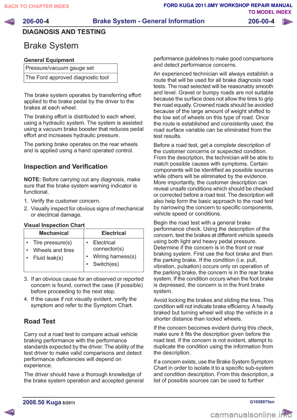
Brake System
General EquipmentPressure/vacuum gauge set
The Ford approved diagnostic tool
The brake system operates by transferring effort
applied to the brake pedal by the driver to the
brakes at each wheel.
The braking effort is distributed to each wheel,
using a hydraulic system. The system is assisted
using a vacuum brake booster that reduces pedal
effort and increases hydraulic pressure.
The parking brake operates on the rear wheels
and is applied using a hand operated control.
Inspection and Verification
NOTE: Before carrying out any diagnosis, make
sure that the brake system warning indicator is
functional.
1. Verify the customer concern.
2. Visually inspect for obvious signs of mechanical or electrical damage.
Visual Inspection Chart
Electrical
Mechanical
• Electricalconnector(s)
• Wiring harness(s)
• Switch(es)
• Tire pressure(s)
• Wheels and tires
• Fluid leak(s)
3. If an obvious cause for an observed or reported concern is found, correct the case (if possible)
before proceeding to the next step.
4. If the cause if not visually evident, verify the symptom and refer to the Symptom Chart.
Road Test
Carry out a road test to compare actual vehicle
braking performance with the performance
standards expected by the driver. The ability of the
test driver to make valid comparisons and detect
performance deficiencies will depend on
experience.
The driver should have a thorough knowledge of
the brake system operation and accepted general performance guidelines to make good comparisons
and detect performance concerns.
An experienced technician will always establish a
route that will be used for all brake diagnosis road
tests. The road selected will be reasonably smooth
and level. Gravel or bumpy roads are not suitable
because the surface does not allow the tires to grip
the road equally. Crowned roads should be avoided
because of the large amount of weight shifted to
the low set of wheels on this type of road. Once
the route is established and consistently used, the
road surface variable can be eliminated from the
test results.
Before a road test, get a complete description of
the customer concerns or suspected condition.
From the description, the technician will be able to
match possible causes with symptoms. Certain
components will be identified as possible sources
while others will be eliminated by the evidence.
More importantly, the customer description can
reveal unsafe conditions which should be checked
or corrected before a road test. The description will
also help form the basic approach to the road test
by narrowing the concern to specific components,
vehicle speed or conditions.
Begin the road test with a general brake
performance check. Using the description of the
concern, test the brakes at different vehicle speeds
using both light and heavy pedal pressure.
Determine if the concern is in the front or rear
braking system. First use the foot brake and then
the parking brake. If the condition (i.e. pull,
vibration, pulsation) occurs only on operation of
the parking brake, the concern is in the rear brake
system. If the condition occurs when the foot brake
is depressed, the concern is in the front brake
system.
Avoid locking the brakes and sliding the tires. This
condition will not indicate brake efficiency. A heavily
braked but turning wheel will stop the vehicle in a
shorter distance than locked wheels.
If the concern becomes evident during this check,
make sure it fits the description given before the
road test. If the concern is not evident, attempt to
duplicate the condition using the information from
the description.
If a concern exists, use the Brake System Symptom
Chart in order to isolate it to a specific sub-system
and condition description. From this description, a
list of possible sources can be used to further
G1058975en2008.50 Kuga8/2011
206-00-
4
Brake System - General Information
206-00- 4
DIAGNOSIS AND TESTING
TO MODEL INDEX
BACK TO CHAPTER INDEX
FORD KUGA 2011.0MY WORKSHOP REPAIR MANUAL
Page 1341 of 2057
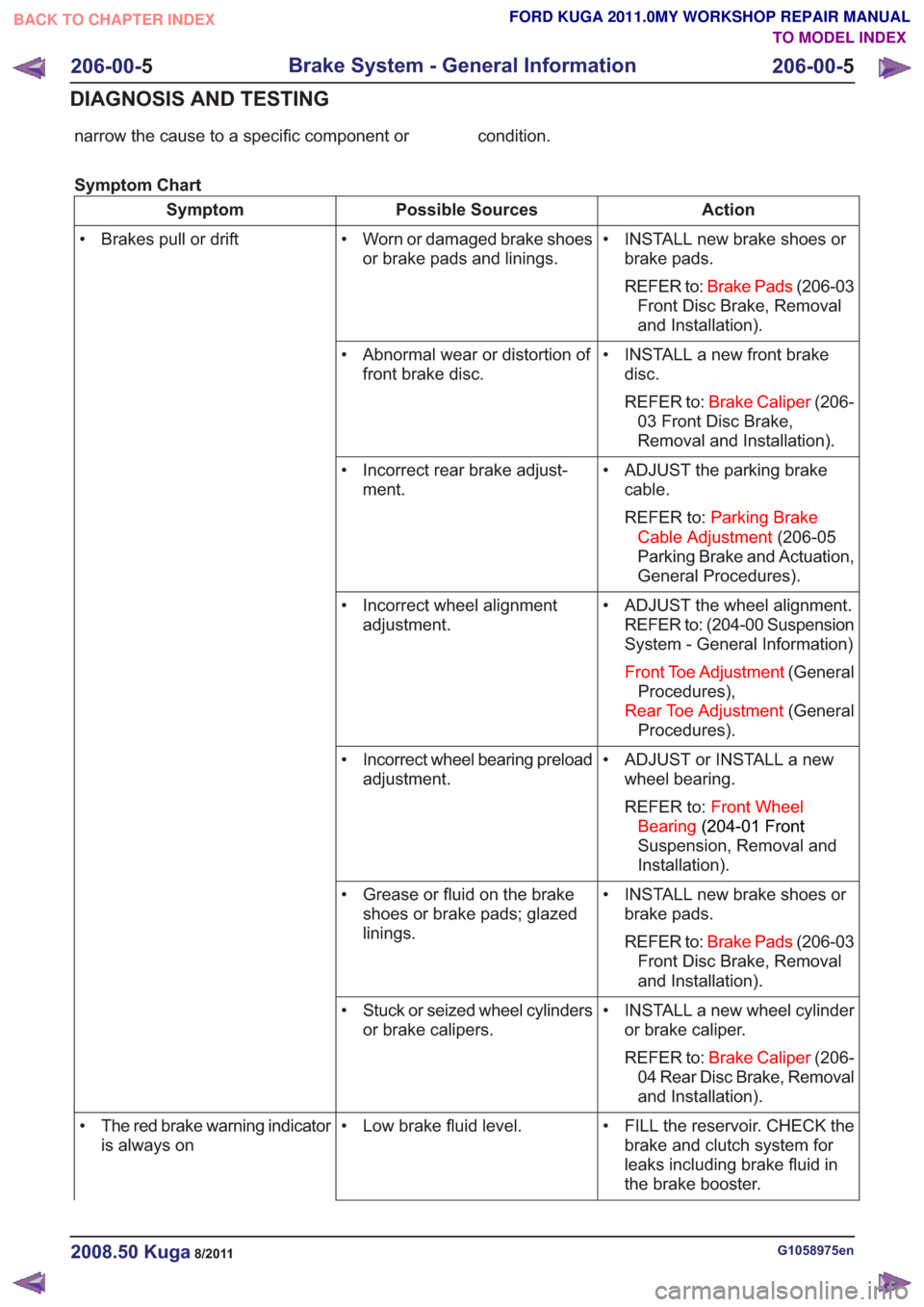
narrow the cause to a specific component or condition.
Symptom Chart
Action
Possible Sources
Symptom
• INSTALL new brake shoes orbrake pads.
REFER to: Brake Pads (206-03
Front Disc Brake, Removal
and Installation).
• Worn or damaged brake shoes
or brake pads and linings.
• Brakes pull or drift
• INSTALL a new front brakedisc.
REFER to: Brake Caliper (206-
03 Front Disc Brake,
Removal and Installation).
• Abnormal wear or distortion of
front brake disc.
• ADJUST the parking brakecable.
REFER to: Parking Brake
Cable Adjustment (206-05
Parking Brake and Actuation,
General Procedures).
• Incorrect rear brake adjust-
ment.
• ADJUST the wheel alignment.REFER to: (204-00 Suspension
System - General Information)
Front Toe Adjustment (General
Procedures),
Rear Toe Adjustment (General
Procedures).
• Incorrect wheel alignment
adjustment.
• ADJUST or INSTALL a newwheel bearing.
REFER to: Front Wheel
Bearing (204-01 Front
Suspension, Removal and
Installation).
• Incorrect wheel bearing preload
adjustment.
• INSTALL new brake shoes orbrake pads.
REFER to: Brake Pads (206-03
Front Disc Brake, Removal
and Installation).
• Grease or fluid on the brake
shoes or brake pads; glazed
linings.
• INSTALL a new wheel cylinderor brake caliper.
REFER to: Brake Caliper (206-
04 Rear Disc Brake, Removal
and Installation).
• Stuck or seized wheel cylinders
or brake calipers.
• FILL the reservoir. CHECK thebrake and clutch system for
leaks including brake fluid in
the brake booster.
• Low brake fluid level.
• The red brake warning indicator
is always on
G1058975en2008.50 Kuga8/2011
206-00- 5
Brake System - General Information
206-00- 5
DIAGNOSIS AND TESTING
TO MODEL INDEX
BACK TO CHAPTER INDEX
FORD KUGA 2011.0MY WORKSHOP REPAIR MANUAL
Page 1342 of 2057
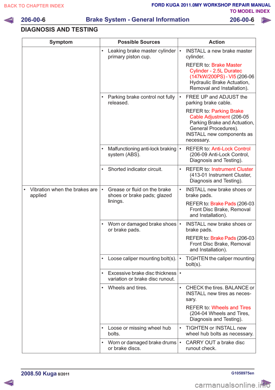
Action
Possible Sources
Symptom
• INSTALL a new brake mastercylinder.
REFER to: Brake Master
Cylinder - 2.5L Duratec
(147kW/200PS) - VI5 (206-06
Hydraulic Brake Actuation,
Removal and Installation).
• Leaking brake master cylinder
primary piston cup.
• FREE UP and ADJUST theparking brake cable.
REFER to: Parking Brake
Cable Adjustment (206-05
Parking Brake and Actuation,
General Procedures).
INSTALL new components as
necessary.
• Parking brake control not fully
released.
• REFER to:Anti-Lock Control
(206-09 Anti-Lock Control,
Diagnosis and Testing).
• Malfunctioning anti-lock braking
system (ABS).
• REFER to:Instrument Cluster
(413-01 Instrument Cluster,
Diagnosis and Testing).
• Shorted indicator circuit.
• INSTALL new brake shoes orbrake pads.
REFER to: Brake Pads (206-03
Front Disc Brake, Removal
and Installation).
• Grease or fluid on the brake
shoes or brake pads; glazed
linings.
• Vibration when the brakes are
applied
• INSTALL new brake shoes orbrake pads.
REFER to: Brake Pads (206-03
Front Disc Brake, Removal
and Installation).
• Worn or damaged brake shoes
or brake pads.
• TIGHTEN the caliper mountingbolt(s).
• Loose caliper mounting bolt(s).
•
• Excessive brake disc thickness
variation or brake disc runout.
• CHECK the tires. BALANCE orINSTALL new tires as neces-
sary.
REFER to: Wheels and Tires
(204-04 Wheels and Tires,
Diagnosis and Testing).
• Wheels and tires.
• TIGHTEN or INSTALL newwheel hub bolts as necessary.
• Loose or missing wheel hub
bolts.
• CARRY OUT a brake discrunout check.
• Worn or damaged brake drums
or brake discs.
G1058975en2008.50 Kuga8/2011
206-00- 6
Brake System - General Information
206-00- 6
DIAGNOSIS AND TESTING
TO MODEL INDEX
BACK TO CHAPTER INDEX
FORD KUGA 2011.0MY WORKSHOP REPAIR MANUAL
Page 1350 of 2057
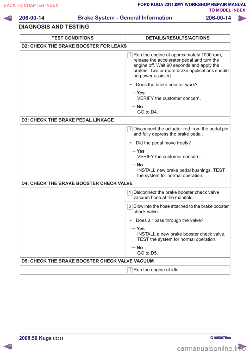
DETAILS/RESULTS/ACTIONS
TEST CONDITIONS
D2: CHECK THE BRAKE BOOSTER FOR LEAKS
1 Run the engine at approximately 1000 rpm,
release the accelerator pedal and turn the
engine off. Wait 90 seconds and apply the
brakes. Two or more brake applications should
be power assisted.
• Does the brake booster work?
zYe s VERIFY the customer concern.
zNoGO to D4 .
D3: CHECK THE BRAKE PEDAL LINKAGE
1 Disconnect the actuator rod from the pedal pin
and fully depress the brake pedal.
• Did the pedal move freely?
zYe s VERIFY the customer concern.
zNoINSTALL new brake pedal bushings. TEST
the system for normal operation.
D4: CHECK THE BRAKE BOOSTER CHECK VALVE
1 Disconnect the brake booster check valve
vacuum hose at the manifold.
2Blow into the hose attached to the brake booster
check valve.
• Does air pass through the valve?
zYe s INSTALL a new brake booster check valve.
TEST the system for normal operation.
zNoGO to D5 .
D5: CHECK THE BRAKE BOOSTER CHECK VALVE VACUUM
1 Run the engine at idle.
G1058975en2008.50 Kuga8/2011
206-00-
14
Brake System - General Information
206-00- 14
DIAGNOSIS AND TESTING
TO MODEL INDEX
BACK TO CHAPTER INDEX
FORD KUGA 2011.0MY WORKSHOP REPAIR MANUAL