Page 1718 of 2057
Turbocharger – Component Location
E97600
12
34
5
Description
Item
Turbocharger heat shield
1
from air filter
2Description
Item
TC (turbocharger)
3
to intercooler
4
Exhaust manifold
5
G1032424en2008.50 Kuga8/2011
303-04B- 2
Fuel Charging and Controls - Turbocharger
—
2.5L Duratec (147kW/200PS) - VI5
303-04B- 2
DESCRIPTION AND OPERATION
TO MODEL INDEX
BACK TO CHAPTER INDEX
FORD KUGA 2011.0MY WORKSHOP REPAIR MANUAL
Page 1766 of 2057
Intake Air Distribution and Filtering – Component Location
E105576
1
2
34
5
6
7
8
9
Description
Item
Intake manifold
1
Air cleaner
2
The MAF (mass air flow) sensor
3
Pipe, air filter to turbocharger
4Description
Item
Turbocharger
5
Pipe, turbocharger to intercooler
6
Charge air cooler
7
Pipe, intercooler to intake manifold
8
Air Intake manifold
9
G1079094en2008.50 Kuga8/2011
303-12- 2
Intake Air Distribution and Filtering
— 2.5L Duratec
(147kW/200PS) - VI5
303-12- 2
DESCRIPTION AND OPERATION
TO MODEL INDEX
BACK TO CHAPTER INDEX
FORD KUGA 2011.0MY WORKSHOP REPAIR MANUAL
Page 1802 of 2057

voltage signal to the PCM corresponding to the
aspirated air mass.
This analogue voltage signal is between 0.5V and
5V. Low mass of intake air produces a low voltage
signal. A high mass of intake air produces a
correspondingly high voltage signal.
The MAF sensor is also capable of detecting the
backflow of the intake air. A sensor element is
heated electrically on the integrated chip and then
cooled by the air flowing through. The regulating
switch supplies the heating current in such a way
that it attains a constant excess temperature in
comparison to the intake air. The mass air flow and
the direction of flow can be derived from this
heating current (given in the form of a signal
voltage). Below a certain voltage value there is a
return flow. The direction is flow is registered by
two sensors pointing in different directions. The
measurement does not require a great deal of
software processing effort, even with a strongly
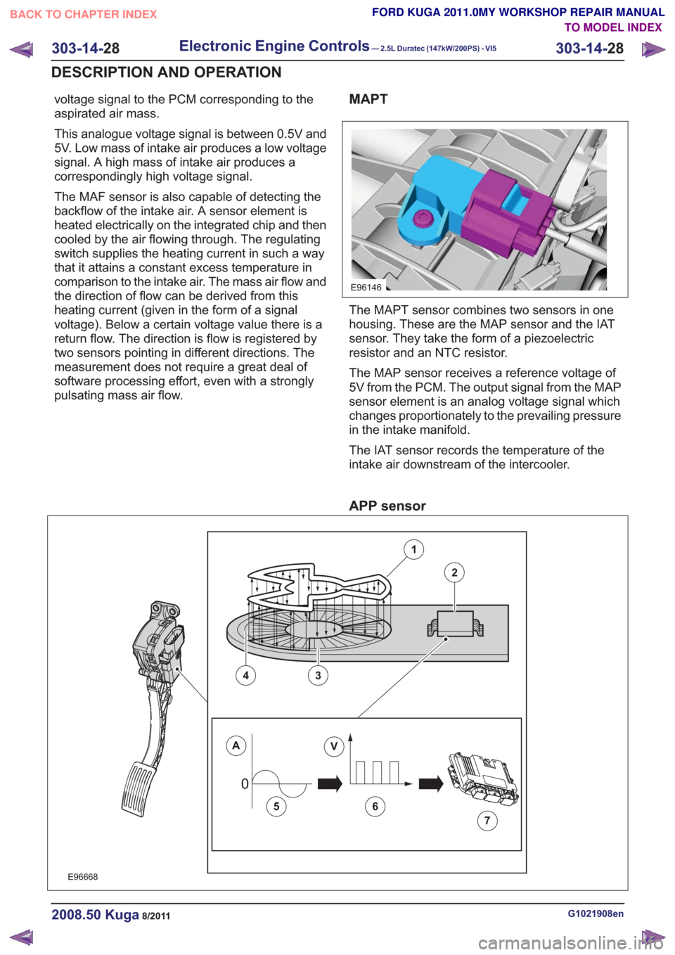
pulsating mass air flow.MAPT
E96146
The MAPT sensor combines two sensors in one
housing. These are the MAP sensor and the IAT
sensor. They take the form of a piezoelectric
resistor and an NTC resistor.
The MAP sensor receives a reference voltage of
5V from the PCM. The output signal from the MAP
sensor element is an analog voltage signal which
changes proportionately to the prevailing pressure
in the intake manifold.
The IAT sensor records the temperature of the
intake air downstream of the intercooler.
APP sensor
00
E96668
1
2
43
AV
56
7
G1021908en2008.50 Kuga8/2011
303-14-28
Electronic Engine Controls— 2.5L Duratec (147kW/200PS) - VI5303-14-
28
DESCRIPTION AND OPERATION
TO MODEL INDEX
BACK TO CHAPTER INDEX
FORD KUGA 2011.0MY WORKSHOP REPAIR MANUAL