2011 FORD KUGA wheel size
[x] Cancel search: wheel sizePage 383 of 2057

Description
Item
Medium speed CAN (controller area
network) bus (MS-CAN)
A
High speed CAN bus (HS-CAN)
B
LIN (local interconnect network) bus
C
Terminating resistors
Drive
DLC (data link connector)
E
GEMRefer to Component Description: ABS
(page ?)
1
Fuel fired booster heater /programmable
fuel fired booster heater
2
The EATC control module
3
Reversing camera module (RVC)
4
Parking aid module (PAM)
5
DDM6
Front driver's side switch unit
7
Driver's side RDM
8
PDM (Passenger Door Module)
9
Passenger side RDM
10
Audio unit/navigation unit
11
CD changer
12 Description
Item
Navigation system module - vehicles
equipped with DVD navigation system with
touch screen (not communicating with the
diagnostic unit)
13
Navigation system display - vehicles
equipped with DVD navigation system with
touch screen (not communicating with the
diagnostic unit)
14
Control module for electronic auxiliary
equipment (BVC)
15
RCM16
Keyless vehicle module (KVM)
17
Instrument Cluster
18
PCM19
Fuel additive system module.
20
ABS module or electronic stability program
module
21
Yaw rate sensor/lateral acceleration
sensor
22
Headlamp Leveling Module
23
All-wheel drive control unit
24
Electrohydraulic power steering module
25
System Operation
General
In a communications network (data bus system),
various modules of different systems are connected
to one another via one or several lines.
The data bus system is used exclusively for
transmitting data between the connected modules,
as well as between the connected modules and
the Ford diagnostic unit.
In a data bus system, complete data blocks are
transmitted instead of single on/off pulses. In
addition to the actual information, these data blocks
also contain data regarding the address of the
module to be addressed, the size of the data block
and information for monitoring the content of each
individual data block.
Data bus systems offer various advantages: • Simplified data transmission between the
modules due to a standardized protocol
• Fewer sensors and connectors
• Improved diagnostic options
• Lower costs
The DLC is connected to the various data bus
systems and to the power supply via the standard
16-pin GEM. The signal for the module
programming is also transferred via the DLC.
In a data bus system, if there is a break in one or
both lines or there is a short to ground or to voltage,
then communication between the modules and
with the Ford diagnostic unit is disturbed or is no
longer possible at all.
In order to be able to establish communication with
one another, the modules of the individual systems G1030779en
2008.50 Kuga 8/2011 418-00-6
Module Communications Network
418-00-6
DESCRIPTION AND OPERATIONTO MODEL INDEX
BACK TO CHAPTER INDEX
FORD KUGA 2011.0MY WORKSHOP REPAIR MANUAL
Page 388 of 2057

Module Configuration
Activation
1.
Install the most up-to-date software version in
the integrated diagnostic system (IDS).
2. In IDS, select the "Module reprogramming"
submenu in the "Module programming" menu
tool box and then follow the instructions.
3. Transfer a new software version (if available)
to the powertrain control module (PCM) using
IDS, if a module-reprogramming of the PCM
may be required in the case of engine running
concerns.
4. Following installation of a wheel/tire
combination, for which the tire-tread
circumference does not correspond to that of
standard tires, the tire size must be changed in
the PCM using IDS. Therefore select the
"Programmable parameters" submenu and enter
the corresponding tire size under the "tire size"
menu item. G1158256en
2008.50 Kuga 8/2011 418-01-2
Module Configuration
418-01-2
GENERAL PROCEDURESTO MODEL INDEX
BACK TO CHAPTER INDEX
FORD KUGA 2011.0MY WORKSHOP REPAIR MANUAL
Page 1168 of 2057
3. If a new lower arm is installed it will benecessary to check and adjust the front wheel
alignment.
REFER to: Front Toe Adjustment (204-00
Suspension System - General Information,
General Procedures)
/ Rear Toe Adjustment (204-00 Suspension
System - General Information, General
Procedures).
Strut or Shock Absorber Inspection
NOTE: Inspect the struts or shock absorber for
signs of oil weepage or leaks. Make sure that the
oil is not from another source.
Weepage:
• deposits a thin film of oil on the strut and spring assembly or shock absorber.
• is normally noticed due to a collection of dust on the strut and spring assembly or shock
absorber.
• occurs during the normal running-in period of 4800 - 8050 km. After this period no new signs
of oil should be visible.
• does not require new struts or shock absorbers to be installed.
Leakage:
• covers the entire strut and spring assembly or shock absorber with oil.
• will drip oil onto the surrounding suspension components.
• requires new struts or shock absorbers to be installed.
Strut or Shock Absorber Testing
NOTE: Struts or shock absorbers must be tested
in the vertical position.
1. Remove both strut and spring assemblies or shock absorbers. The piston rods should extend.
• Disassemble the strut and spring assemblies.
REFER to: Front Strut and Spring Assembly
(204-01 Front Suspension, Removal and
Installation).
2. Compress the piston rods. Both piston rods should offer the same resistance when
compressing.
3. Compress and release the piston rods. The piston rods should extent equally. 4. Compress and pull the piston rod in the vertical
position. Feel if the resistance force at the point
of direction change-over is perceptible without
a lag. If a lag is perceptible it is an indication of
damper valve damage and new struts or shock
absorbers must be installed. REFER to:
Front Strut and Spring Assembly (204-01 Front
Suspension, Removal and Installation),
Spring (204-02 Rear Suspension, Removal and
Installation).
Load-Levelling Shock Absorber
1. With the vehicle unladen, measure and note the dimensions between the base of the wheel rim
and the top of the rear fender on both sides.
• The measurements on both sides should be approximately equal.
2. With a load of 4 average size adults and a 100 kg weight, measure and note the dimensions
between the base of the wheel rim and the top
of the rear fender on both sides.
3. NOTE: Due to the internal ratchet mechanism of the suspension components, the height
of the rear of the vehicle should rise during
the road test.
With a load of 4 average size adults and a 100
kg weight, drive the vehicle for 3 km on a road
of normal condition.
4. With a load of 4 average size adults and a 100 kg weight, measure and note the dimensions
between the base of the wheel rim and the top
of the rear fender on both sides.
5. If the dimensions on both sides are no longer approximately equal, install new load levelling
shock absorbers.
REFER to: Spring(204-02 Rear Suspension,
Removal and Installation).
6. NOTE: Due to the internal ratchet mechanism of the suspension components, the height
of the rear of the vehicle should rise during
the road test.
If the dimensions are approximately equal,
unload the vehicle and drive the vehicle for 3
km on a road of normal condition.
7. With the vehicle unladen, measure and note the dimensions between the base of the wheel rim
and the top of the rear fender on both sides.
Check the final dimensions with the original
dimensions taken in the unladen condition.
G1080717en2008.50 Kuga8/2011
204-00- 13
Suspension System - General Information
204-00- 13
DIAGNOSIS AND TESTING
TO MODEL INDEX
BACK TO CHAPTER INDEX
FORD KUGA 2011.0MY WORKSHOP REPAIR MANUAL
Page 1229 of 2057
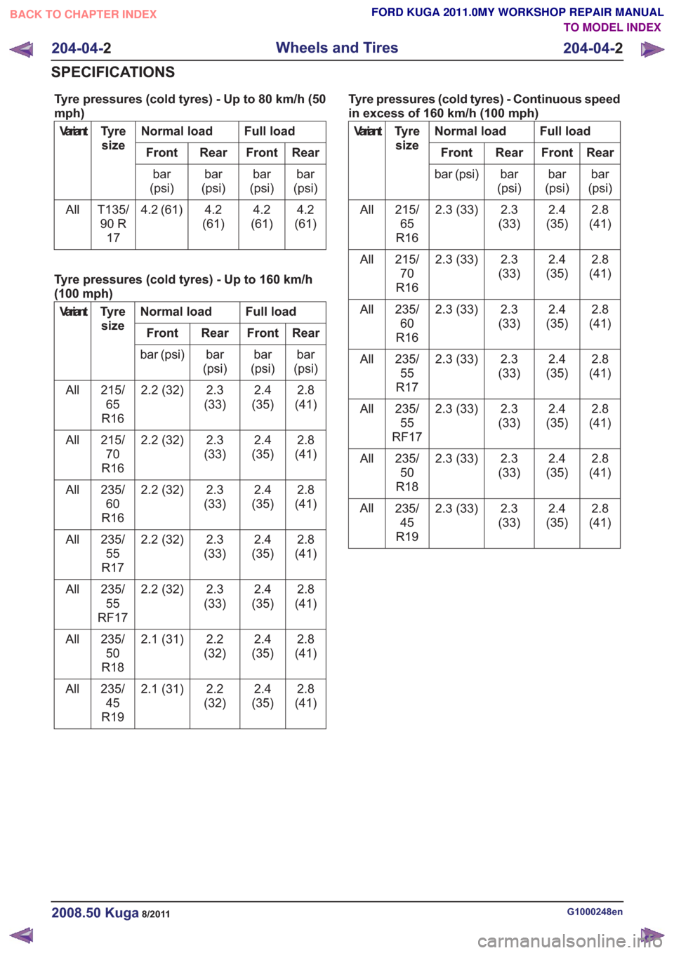
Tyre pressures (cold tyres) - Up to 80 km/h (50
mph)
Full load
Normal load
Tyre
size
Variant
Rear
Front
Rear
Front
bar
(psi)
bar
(psi)
bar
(psi)
bar
(psi)
4.2
(61)
4.2
(61)
4.2
(61)
4.2 (61)
T135/
90 R 17
All
Tyre pressures (cold tyres) - Up to 160 km/h
(100 mph)
Full load
Normal load
Tyre
size
Variant
Rear
Front
Rear
Front
bar
(psi)
bar
(psi)
bar
(psi)
bar (psi)
2.8
(41)
2.4
(35)
2.3
(33)
2.2 (32)
215/
65
R16
All
2.8
(41)
2.4
(35)
2.3
(33)
2.2 (32)
215/
70
R16
All
2.8
(41)
2.4
(35)
2.3
(33)
2.2 (32)
235/
60
R16
All
2.8
(41)
2.4
(35)
2.3
(33)
2.2 (32)
235/
55
R17
All
2.8
(41)
2.4
(35)
2.3
(33)
2.2 (32)
235/
55
RF17
All
2.8
(41)
2.4
(35)
2.2
(32)
2.1 (31)
235/
50
R18
All
2.8
(41)
2.4
(35)
2.2
(32)
2.1 (31)
235/
45
R19
All Tyre pressures (cold tyres) - Continuous speed
in excess of 160 km/h (100 mph)
Full load
Normal load
Tyre
size
Variant
Rear
Front
Rear
Front
bar
(psi)
bar
(psi)
bar
(psi)
bar (psi)
2.8
(41)
2.4
(35)
2.3
(33)
2.3 (33)
215/
65
R16
All
2.8
(41)
2.4
(35)
2.3
(33)
2.3 (33)
215/
70
R16
All
2.8
(41)
2.4
(35)
2.3
(33)
2.3 (33)
235/
60
R16
All
2.8
(41)
2.4
(35)
2.3
(33)
2.3 (33)
235/
55
R17
All
2.8
(41)
2.4
(35)
2.3
(33)
2.3 (33)
235/
55
RF17
All
2.8
(41)
2.4
(35)
2.3
(33)
2.3 (33)
235/
50
R18
All
2.8
(41)
2.4
(35)
2.3
(33)
2.3 (33)
235/
45
R19
All
G1000248en2008.50 Kuga8/2011
204-04-
2
Wheels and Tires
204-04- 2
SPECIFICATIONS
TO MODEL INDEX
BACK TO CHAPTER INDEX
FORD KUGA 2011.0MY WORKSHOP REPAIR MANUAL
Page 1230 of 2057
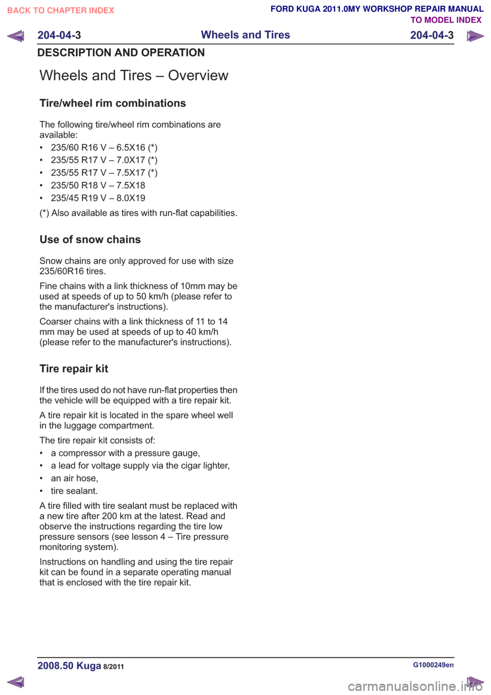
Wheels and Tires – Overview
Tire/wheel rim combinations
The following tire/wheel rim combinations are
available:
• 235/60 R16 V – 6.5X16 (*)
• 235/55 R17 V – 7.0X17 (*)
• 235/55 R17 V – 7.5X17 (*)
• 235/50 R18 V – 7.5X18
• 235/45 R19 V – 8.0X19
(*) Also available as tires with run-flat capabilities.
Use of snow chains
Snow chains are only approved for use with size
235/60R16 tires.
Fine chains with a link thickness of 10mm may be
used at speeds of up to 50 km/h (please refer to
the manufacturer's instructions).
Coarser chains with a link thickness of 11 to 14
mm may be used at speeds of up to 40 km/h
(please refer to the manufacturer's instructions).
Tire repair kit
If the tires used do not have run-flat properties then
the vehicle will be equipped with a tire repair kit.
A tire repair kit is located in the spare wheel well
in the luggage compartment.
The tire repair kit consists of:
• a compressor with a pressure gauge,
• a lead for voltage supply via the cigar lighter,
• an air hose,
• tire sealant.
A tire filled with tire sealant must be replaced with
a new tire after 200 km at the latest. Read and
observe the instructions regarding the tire low
pressure sensors (see lesson 4 – Tire pressure
monitoring system).
Instructions on handling and using the tire repair
kit can be found in a separate operating manual
that is enclosed with the tire repair kit.
G1000249en2008.50 Kuga8/2011
204-04-3
Wheels and Tires
204-04- 3
DESCRIPTION AND OPERATION
TO MODEL INDEX
BACK TO CHAPTER INDEX
FORD KUGA 2011.0MY WORKSHOP REPAIR MANUAL
Page 1231 of 2057
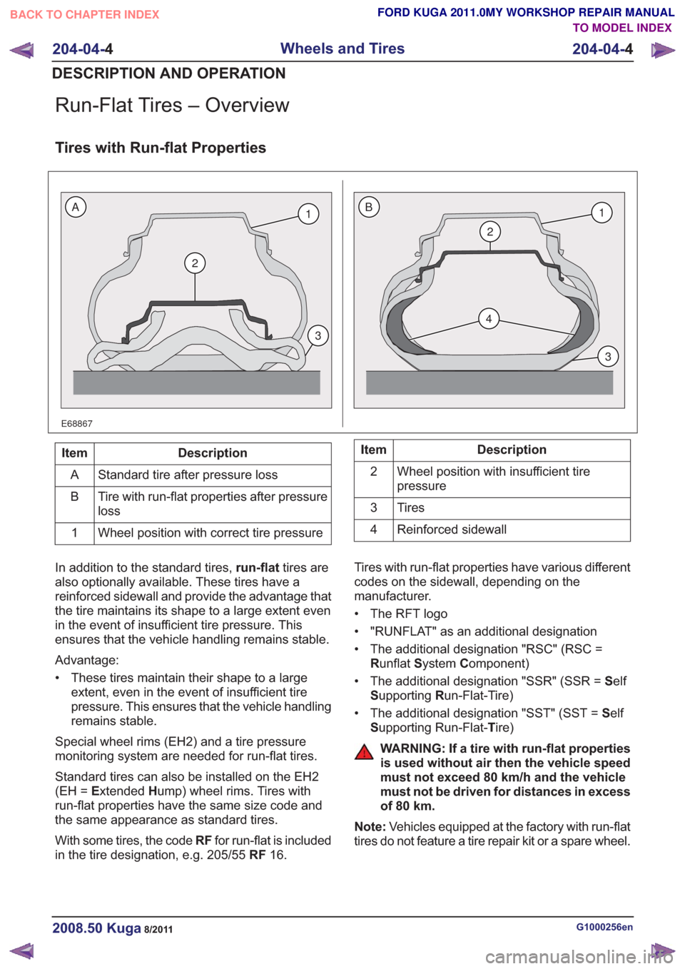
Run-Flat Tires – Overview
Tires with Run-flat Properties
E68867
2
1
3
2
4
1
3
BA
Description
Item
Standard tire after pressure loss
A
Tire with run-flat properties after pressure
loss
B
Wheel position with correct tire pressure
1Description
Item
Wheel position with insufficient tire
pressure
2
Tires
3
Reinforced sidewall
4
In addition to the standard tires, run-flattires are
also optionally available. These tires have a
reinforced sidewall and provide the advantage that
the tire maintains its shape to a large extent even
in the event of insufficient tire pressure. This
ensures that the vehicle handling remains stable.
Advantage:
• These tires maintain their shape to a large extent, even in the event of insufficient tire
pressure. This ensures that the vehicle handling
remains stable.
Special wheel rims (EH2) and a tire pressure
monitoring system are needed for run-flat tires.
Standard tires can also be installed on the EH2
(EH = Extended Hump) wheel rims. Tires with
run-flat properties have the same size code and
the same appearance as standard tires.
With some tires, the code RFfor run-flat is included
in the tire designation, e.g. 205/55 RF16. Tires with run-flat properties have various different
codes on the sidewall, depending on the
manufacturer.
• The RFT logo
• "RUNFLAT" as an additional designation
• The additional designation "RSC" (RSC =
Runflat System Component)
• The additional designation "SSR" (SSR = Self
S upporting Run-Flat-Tire)
• The additional designation "SST" (SST = Self
S upporting Run-Flat- Tire)
WARNING: If a tire with run-flat properties
is used without air then the vehicle speed
must not exceed 80 km/h and the vehicle
must not be driven for distances in excess
of 80 km.
Note: Vehicles equipped at the factory with run-flat
tires do not feature a tire repair kit or a spare wheel.
G1000256en2008.50 Kuga8/2011
204-04- 4
Wheels and Tires
204-04- 4
DESCRIPTION AND OPERATION
TO MODEL INDEX
BACK TO CHAPTER INDEX
FORD KUGA 2011.0MY WORKSHOP REPAIR MANUAL
Page 1433 of 2057
generate a square wave output signal. The signal
acts in proportion to the rotational speed of the
sensor ring. The ABS sensor rings are built into
the seals in the front wheel bearings. The ABS
module evaluates the signals from all four sensors
to calculate a vehicle speed signal based on the
rotational speeds of all wheels. The road speed is
transmitted on the CAN bus. The powertrain controlmodule (PCM) uses this signal and the
programmed tire size to calculate the vehicle
speed. The calculated vehicle speed is forwarded
on the CAN bus and is requested by other control
units that need this input information.
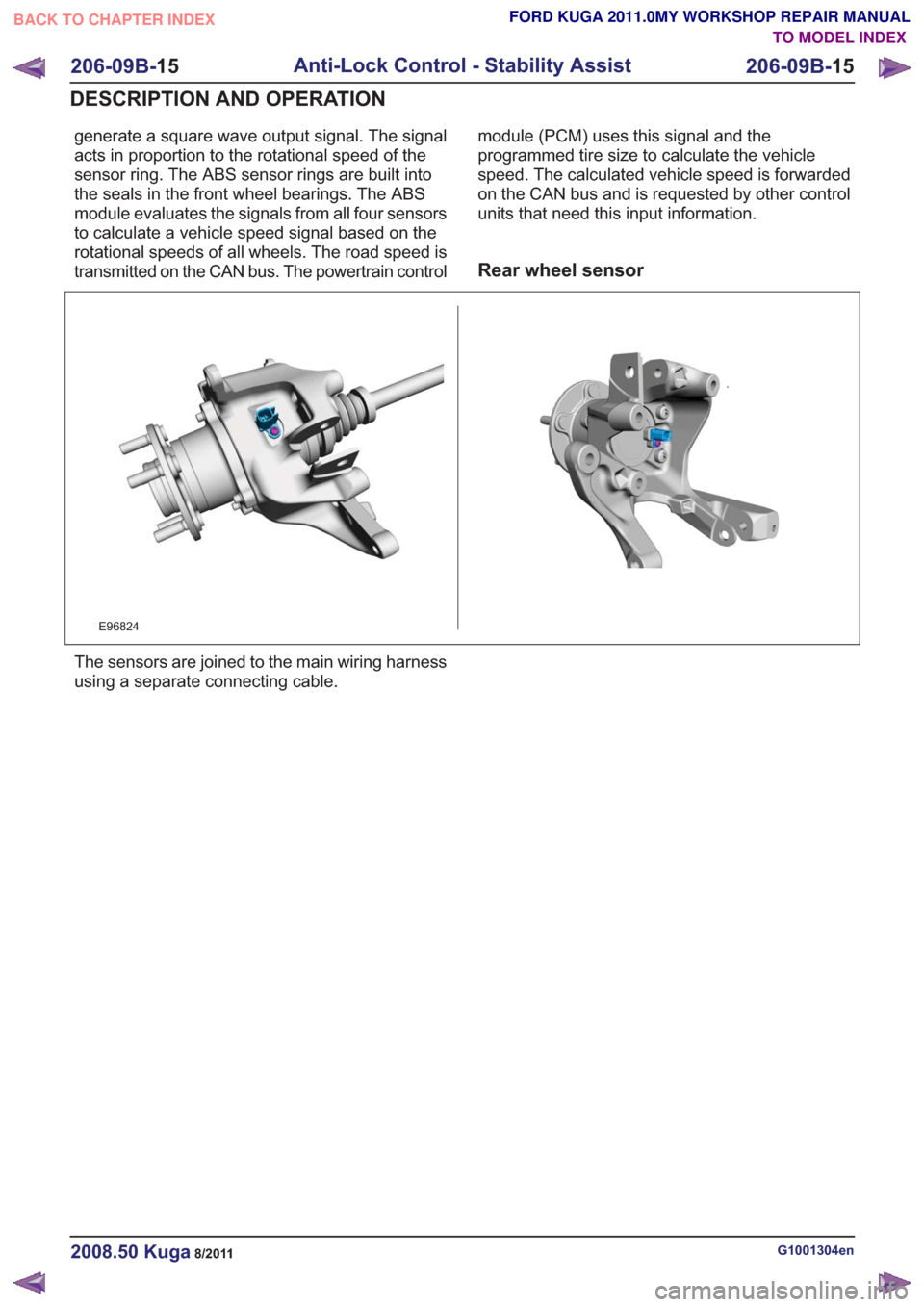
Rear wheel sensor
E96824
The sensors are joined to the main wiring harness
using a separate connecting cable.
G1001304en2008.50 Kuga8/2011
206-09B-
15
Anti-Lock Control - Stability Assist
206-09B- 15
DESCRIPTION AND OPERATION
TO MODEL INDEX
BACK TO CHAPTER INDEX
FORD KUGA 2011.0MY WORKSHOP REPAIR MANUAL