2011 FORD KUGA wheel bolts
[x] Cancel search: wheel boltsPage 80 of 2057

Noise Conditions
• Gear noise is typically a howling or whining dueto gear damage or incorrect bearing preload. It
can occur at various speeds and driving
conditions, or it can be continuous.
• Chuckle is a particular rattling noise that sounds like a stick against the spokes of a spinning
bicycle wheel. It occurs while decelerating from
64 km/h (40 mph) and can usually be heard all
the way to a stop. The frequency varies with
vehicle speed.
• Knock is very similar to chuckle, though it may be louder and occurs on acceleration or
deceleration. The teardown will disclose what
has to be corrected.
Clicking, popping or grinding noises may be caused
by the following:
• worn, damaged or incorrectly installed wheel bearing, suspension or brake component.
Check and rule out tires, exhaust and trim items
before disassembling the transmission to diagnose
and correct gear noise.
The noises described under Road Test usually
have specific causes that can be diagnosed by
observation as the unit is disassembled. The initial
clues are the type of noise heard on the road test
and driving conditions.
Vibration Conditions
Vibration at highway speeds may be caused by
the following:
• out-of-balance front or rear wheels.
• out-of-round tires.
Shudder or vibration during acceleration may be
caused by the following:
• damaged powertrain/drivetrain mounts.
• excessively high constant velocity (CV) joint operating angles caused by incorrect ride height.
Check ride height, verify correct spring rate and
check items under inoperative conditions.
Road Test
A gear-driven unit will produce a certain amount
of noise. Some noise is acceptable and may be
audible at certain speeds or under various driving
conditions, as on a newly paved asphalt road. The slight noise is in no way detrimental and must be
considered normal.
The road test and customer interview (if available)
provide information needed to identify the condition
and give direction to the correct starting point for
diagnosis.
1. Make notes throughout the diagnosis routine.
Make sure to write down even the smallest bit
of information, because it may turn out to be the
most important.
2. Do not touch anything until a road test and a thorough visual inspection of the vehicle have
been carried out. Leave the tire pressures and
vehicle load just where they were when the
condition was first observed. Adjusting tire
pressures, vehicle load or making other
adjustments may reduce the condition(s)
intensity to a point where it cannot be identified
clearly. It may also inject something new into
the system, preventing correct diagnosis.
3. Make a visual inspection as part of the preliminary diagnosis routine, writing down
anything that does not look right. Note tire
pressures, but do not adjust them yet. Note
leaking fluids, loose nuts and bolts, or bright
spots where components may be rubbing
against each other. Check the load space for
unusual loads.
4. Road test the vehicle and define the condition by reproducing it several times during the road
test.
5. Carry out the Road Test Quick Checks as soon as the condition is reproduced. This will identify
the correct diagnostic procedure. Carry out the
Road Test Quick Checks more than once to
verify they are providing a valid result.
Remember, the Road Test Quick Checks may
not tell where the concern is, but they will tell
where it is not.
Road Test Quick Checks
1. 24-80 km/h (15-50 mph): with light acceleration,a moaning noise is heard and possibly a
vibration felt in the front floor panel. It is usually
worse at a particular engine speed and at a
particular throttle setting during acceleration at
that speed. It may also produce a moaning
sound, depending on what component is
causing it. REFER to Tip-in Moan in the
Driveline Noise and Vibration Symptom Chart.
2. Acceleration/Deceleration: With slow acceleration and deceleration, a shake is
G37349en2008.50 Kuga8/2011
100-04- 3
Noise, Vibration and Harshness
100-04- 3
DIAGNOSIS AND TESTING
TO MODEL INDEX
BACK TO CHAPTER INDEX
FORD KUGA 2011.0MY WORKSHOP REPAIR MANUAL
Page 89 of 2057

Action
Possible Sources
Symptom
Certain amount of noise level
acceptable, not a safety critical
item.
Power steering return lines.
Power steering system knock/
clonk noise – sounds almost
identical to column knock that
occurs when driving and
cornering over cobbled stones or
rough roads. Noise may appear
to emanate from a location closer
to the floor than that for column
knock (Sounds like metallic noise
but is created by pressure
impulse in gear and return line –
similar to a sound like quickly
turning off a water tap). Certain amount of noise level
acceptable, not a safety critical
item.
High power assist gain of power
steering gear valve (steering gear
design - no quality issue).
Certain amount of noise level
acceptable, not a safety critical
item.
High power steering pump flow
rate (by design).
Power Steering Column Knock Noise
Test Condition
Listen for steering knock noise in the following test
conditions with windows closed. 1. Drive over cobbled stones at low speed 16-40
km/h (10-25 mph) with and without steering
input carefully listening for knock sounds.
2. Drive over straight tar strips, road rails or 25 mm tall harshness strips at low speed 16-40 km/h
(10-25 mph) both driving straight and with
moderate cornering.
Action
Possible Sources
Symptom
CHECK the steering column
retaining bolts and attachments
to the steering column and
secure if necessary.
Steering column or steering
column shaft.
Power steering system column
knock noise – a loose sounding
rattle or vibration coming from the
column. Noticeable by hearing
and touch. Check steering column and
intermediate shaft for free play or
loose components.
REFER to:
Steering System (211-
00 Steering System - General
Information, Diagnosis and
Testing).
Power Steering Toc-Toc Noise
Test Condition
Listen for steering toc-toc noise with the engine
speed at idle and the vehicle parked, automatic
transmission in "P" (PARK) or manual transmission
in neutral and the windows closed. 1. Turn the steering wheel from left to right abruptly
changing direction.
2. Drive the vehicle for low speed parking manoeuvres constantly changing steering
direction.
G37349en2008.50 Kuga8/2011
100-04- 11
Noise, Vibration and Harshness
100-04- 11
DIAGNOSIS AND TESTING
TO MODEL INDEX
BACK TO CHAPTER INDEX
FORD KUGA 2011.0MY WORKSHOP REPAIR MANUAL
Page 1159 of 2057
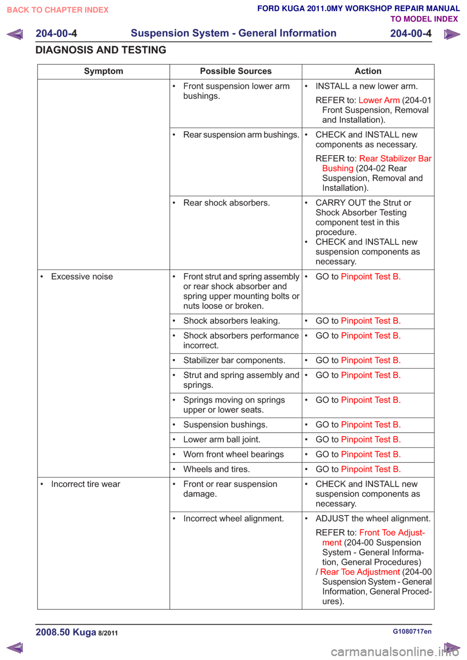
Action
Possible Sources
Symptom
• INSTALL a new lower arm.REFER to: Lower Arm (204-01
Front Suspension, Removal
and Installation).
• Front suspension lower arm
bushings.
• CHECK and INSTALL newcomponents as necessary.
REFER to: Rear Stabilizer Bar
Bushing (204-02 Rear
Suspension, Removal and
Installation).
• Rear suspension arm bushings.
• CARRY OUT the Strut orShock Absorber Testing
component test in this
procedure.
• CHECK and INSTALL new suspension components as
necessary.
• Rear shock absorbers.
• GO toPinpoint Test B.
• Front strut and spring assembly
or rear shock absorber and
spring upper mounting bolts or
nuts loose or broken.
• Excessive noise
• GO toPinpoint Test B.
• Shock absorbers leaking.
• GO toPinpoint Test B.
• Shock absorbers performance
incorrect.
• GO toPinpoint Test B.
• Stabilizer bar components.
• GO toPinpoint Test B.
• Strut and spring assembly and
springs.
• GO toPinpoint Test B.
• Springs moving on springs
upper or lower seats.
• GO toPinpoint Test B.
• Suspension bushings.
• GO toPinpoint Test B.
• Lower arm ball joint.
• GO toPinpoint Test B.
• Worn front wheel bearings
• GO toPinpoint Test B.
• Wheels and tires.
• CHECK and INSTALL newsuspension components as
necessary.
• Front or rear suspension
damage.
• Incorrect tire wear
• ADJUST the wheel alignment.REFER to: Front Toe Adjust-
ment (204-00 Suspension
System - General Informa-
tion, General Procedures)
/ Rear Toe Adjustment (204-00
Suspension System - General
Information, General Proced-
ures).
• Incorrect wheel alignment.
G1080717en2008.50 Kuga8/2011
204-00-
4
Suspension System - General Information
204-00- 4
DIAGNOSIS AND TESTING
TO MODEL INDEX
BACK TO CHAPTER INDEX
FORD KUGA 2011.0MY WORKSHOP REPAIR MANUAL
Page 1163 of 2057
DETAILS/RESULTS/ACTIONS
TEST CONDITIONS
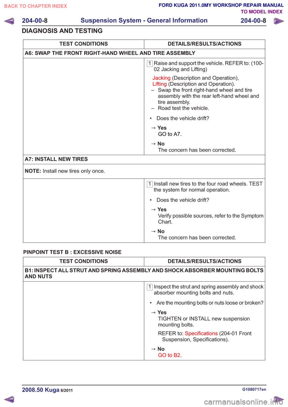
A6: SWAP THE FRONT RIGHT-HAND WHEEL AND TIRE ASSEMBLY
1 Raise and support the vehicle. REFER to: (100-
02 Jacking and Lifting)
Jacking (Description and Operation),
Lifting (Description and Operation).
– Swap the front right-hand wheel and tire assembly with the rear left-hand wheel and
tire assembly.
– Road test the vehicle.
• Does the vehicle drift?
zYe s GO to A7.
zNoThe concern has been corrected.
A7: INSTALL NEW TIRES
NOTE: Install new tires only once.
1Install new tires to the four road wheels. TEST
the system for normal operation.
• Does the vehicle drift?
zYe s Verify possible sources, refer to the Symptom
Chart.
zNoThe concern has been corrected.
PINPOINT TEST B : EXCESSIVE NOISE
DETAILS/RESULTS/ACTIONS
TEST CONDITIONS
B1: INSPECT ALL STRUT AND SPRING ASSEMBLY AND SHOCK ABSORBER MOUNTING BOLTS
AND NUTS
1 Inspect the strut and spring assembly and shock
absorber mounting bolts and nuts.
• Are the mounting bolts or nuts loose or broken?
zYe s TIGHTEN or INSTALL new suspension
mounting bolts.
REFER to: Specifications (204-01 Front
Suspension, Specifications).
zNo
GO to B2.
G1080717en2008.50 Kuga8/2011
204-00- 8
Suspension System - General Information
204-00- 8
DIAGNOSIS AND TESTING
TO MODEL INDEX
BACK TO CHAPTER INDEX
FORD KUGA 2011.0MY WORKSHOP REPAIR MANUAL
Page 1166 of 2057
DETAILS/RESULTS/ACTIONS
TEST CONDITIONS
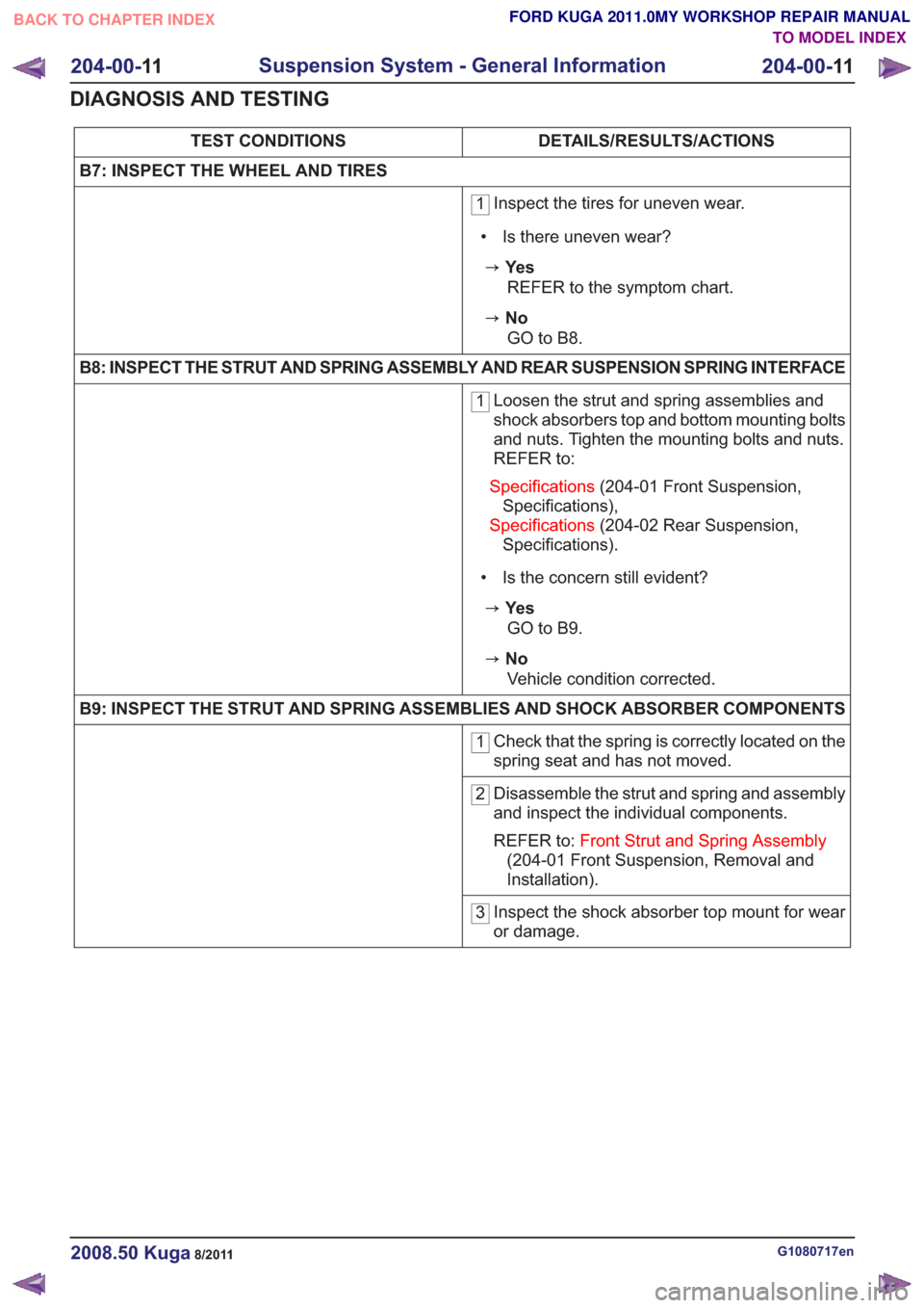
B7: INSPECT THE WHEEL AND TIRES
1 Inspect the tires for uneven wear.
• Is there uneven wear?
zYe s REFER to the symptom chart.
zNoGO to B8.
B8: INSPECT THE STRUT AND SPRING ASSEMBLY AND REAR SUSPENSION SPRING INTERFACE
1 Loosen the strut and spring assemblies and
shock absorbers top and bottom mounting bolts
and nuts. Tighten the mounting bolts and nuts.
REFER to:
Specifications (204-01 Front Suspension,
Specifications),
Specifications (204-02 Rear Suspension,
Specifications).
• Is the concern still evident?
zYe s GO to B9.
zNoVehicle condition corrected.
B9: INSPECT THE STRUT AND SPRING ASSEMBLIES AND SHOCK ABSORBER COMPONENTS
1 Check that the spring is correctly located on the
spring seat and has not moved.
2Disassemble the strut and spring and assembly
and inspect the individual components.
REFER to:
Front Strut and Spring Assembly
(204-01 Front Suspension, Removal and
Installation).
3 Inspect the shock absorber top mount for wear
or damage.
G1080717en2008.50 Kuga8/2011
204-00-
11
Suspension System - General Information
204-00- 11
DIAGNOSIS AND TESTING
TO MODEL INDEX
BACK TO CHAPTER INDEX
FORD KUGA 2011.0MY WORKSHOP REPAIR MANUAL
Page 1171 of 2057
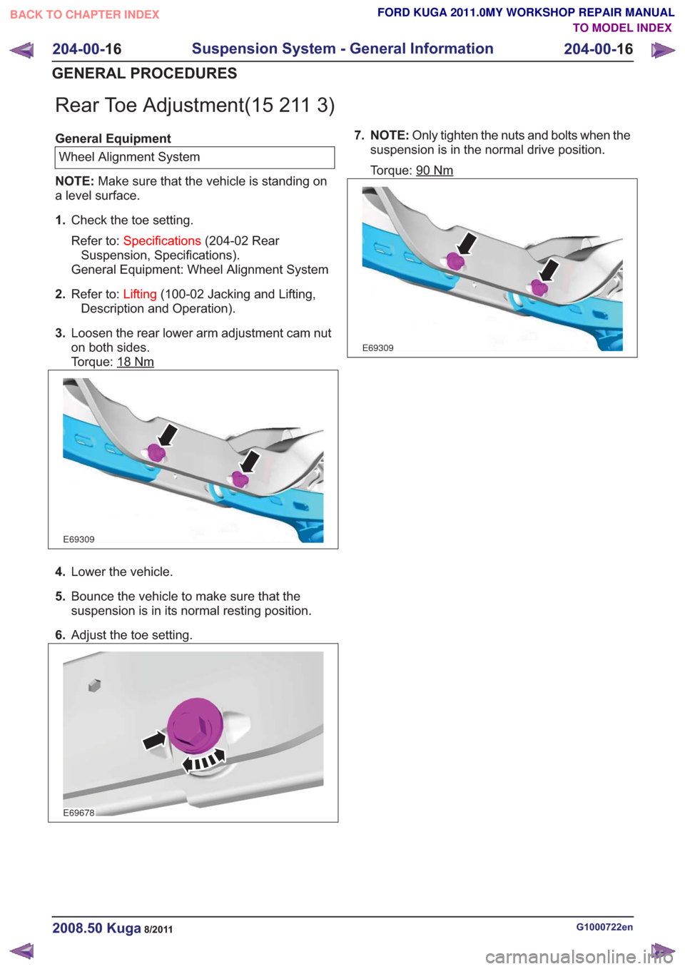
Rear Toe Adjustment(15 211 3)
General EquipmentWheel Alignment System
NOTE: Make sure that the vehicle is standing on
a level surface.
1. Check the toe setting.
Refer to: Specifications (204-02 Rear
Suspension, Specifications).
General Equipment: Wheel Alignment System
2. Refer to: Lifting(100-02 Jacking and Lifting,
Description and Operation).
3. Loosen the rear lower arm adjustment cam nut
on both sides.
Torque: 18
Nm
E69309
4.Lower the vehicle.
5. Bounce the vehicle to make sure that the
suspension is in its normal resting position.
6. Adjust the toe setting.
E69678
7. NOTE: Only tighten the nuts and bolts when the
suspension is in the normal drive position.
Torque: 90
Nm
E69309
G1000722en2008.50 Kuga8/2011
204-00- 16
Suspension System - General Information
204-00- 16
GENERAL PROCEDURES
TO MODEL INDEX
BACK TO CHAPTER INDEX
FORD KUGA 2011.0MY WORKSHOP REPAIR MANUAL
Page 1342 of 2057
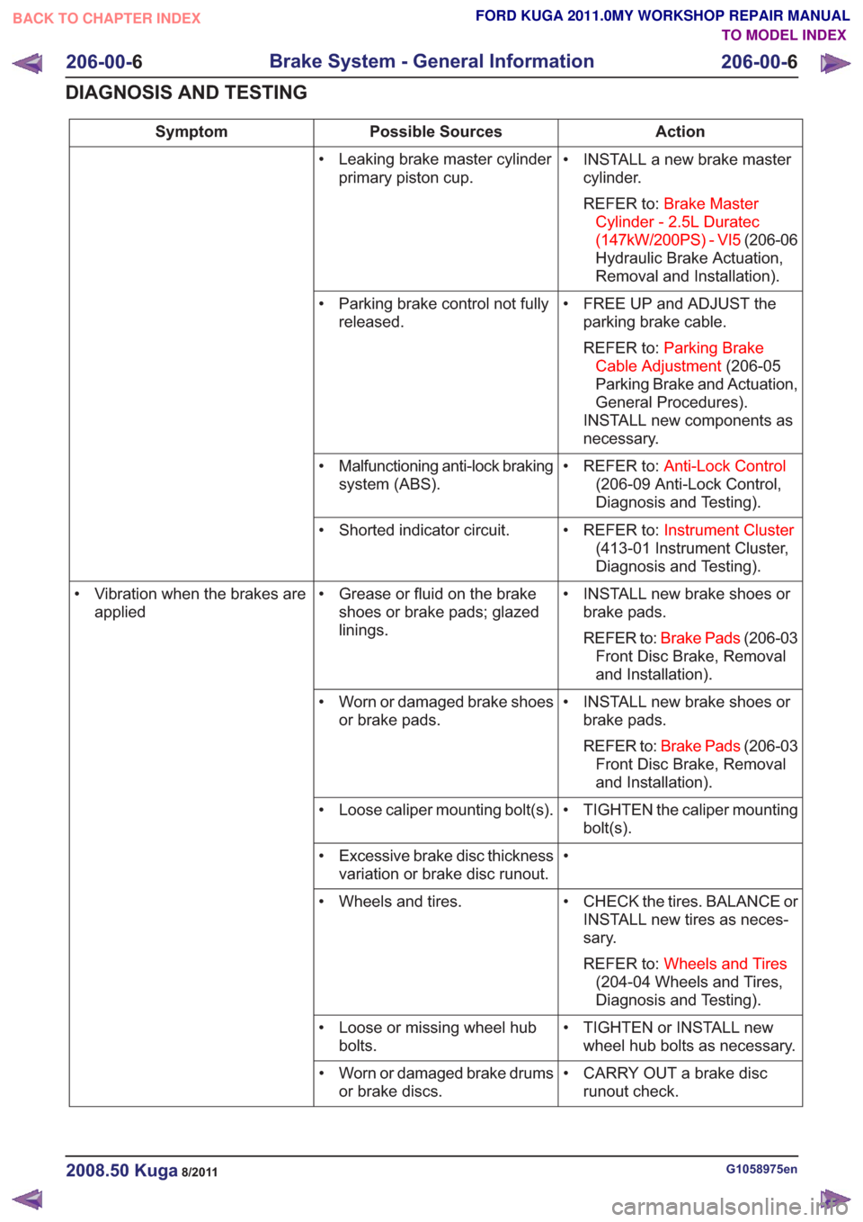
Action
Possible Sources
Symptom
• INSTALL a new brake mastercylinder.
REFER to: Brake Master
Cylinder - 2.5L Duratec
(147kW/200PS) - VI5 (206-06
Hydraulic Brake Actuation,
Removal and Installation).
• Leaking brake master cylinder
primary piston cup.
• FREE UP and ADJUST theparking brake cable.
REFER to: Parking Brake
Cable Adjustment (206-05
Parking Brake and Actuation,
General Procedures).
INSTALL new components as
necessary.
• Parking brake control not fully
released.
• REFER to:Anti-Lock Control
(206-09 Anti-Lock Control,
Diagnosis and Testing).
• Malfunctioning anti-lock braking
system (ABS).
• REFER to:Instrument Cluster
(413-01 Instrument Cluster,
Diagnosis and Testing).
• Shorted indicator circuit.
• INSTALL new brake shoes orbrake pads.
REFER to: Brake Pads (206-03
Front Disc Brake, Removal
and Installation).
• Grease or fluid on the brake
shoes or brake pads; glazed
linings.
• Vibration when the brakes are
applied
• INSTALL new brake shoes orbrake pads.
REFER to: Brake Pads (206-03
Front Disc Brake, Removal
and Installation).
• Worn or damaged brake shoes
or brake pads.
• TIGHTEN the caliper mountingbolt(s).
• Loose caliper mounting bolt(s).
•
• Excessive brake disc thickness
variation or brake disc runout.
• CHECK the tires. BALANCE orINSTALL new tires as neces-
sary.
REFER to: Wheels and Tires
(204-04 Wheels and Tires,
Diagnosis and Testing).
• Wheels and tires.
• TIGHTEN or INSTALL newwheel hub bolts as necessary.
• Loose or missing wheel hub
bolts.
• CARRY OUT a brake discrunout check.
• Worn or damaged brake drums
or brake discs.
G1058975en2008.50 Kuga8/2011
206-00- 6
Brake System - General Information
206-00- 6
DIAGNOSIS AND TESTING
TO MODEL INDEX
BACK TO CHAPTER INDEX
FORD KUGA 2011.0MY WORKSHOP REPAIR MANUAL
Page 1374 of 2057
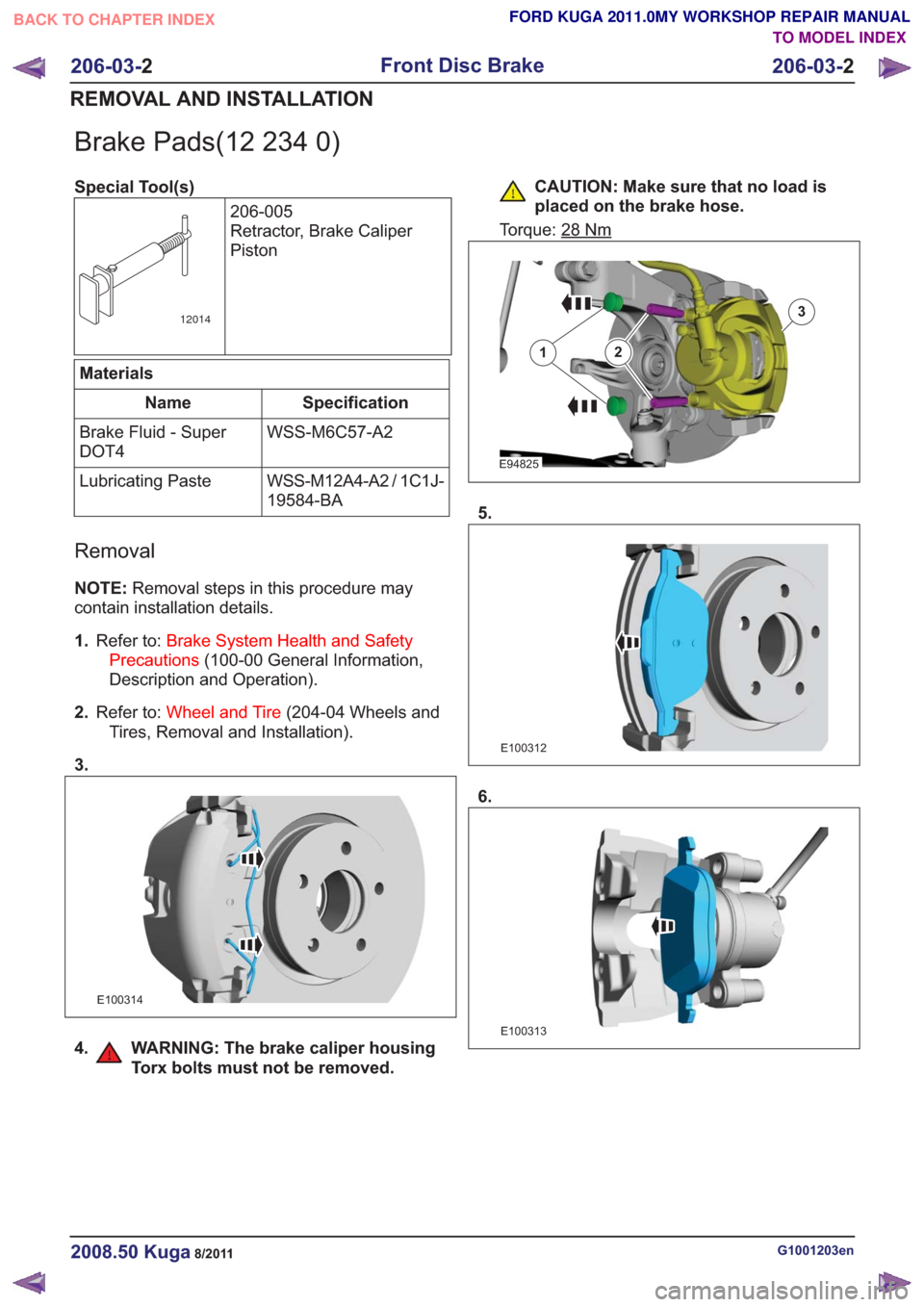
Brake Pads(12 234 0)
Special Tool(s)206-005
Retractor, Brake Caliper
Piston
12014
Materials
Specification
Name
WSS-M6C57-A2
Brake Fluid - Super
DOT4
WSS-M12A4-A2 / 1C1J-
19584-BA
Lubricating Paste
Removal
NOTE:
Removal steps in this procedure may
contain installation details.
1. Refer to: Brake System Health and Safety
Precautions (100-00 General Information,
Description and Operation).
2. Refer to: Wheel and Tire (204-04 Wheels and
Tires, Removal and Installation).
3.
E100314
4. WARNING: The brake caliper housing Torx bolts must not be removed.
CAUTION: Make sure that no load is
placed on the brake hose.
Torque: 28
Nm
E94825
12
3
5.
E100312
6.
E100313
G1001203en2008.50 Kuga8/2011
206-03- 2
Front Disc Brake
206-03- 2
REMOVAL AND INSTALLATION
TO MODEL INDEX
BACK TO CHAPTER INDEX
FORD KUGA 2011.0MY WORKSHOP REPAIR MANUAL