2011 FORD KUGA turbo
[x] Cancel search: turboPage 190 of 2057

Instrument Cluster
Refer to
Wiring Diagrams Section 413-01, for
schematic and connector information. General Equipment
The Ford approved diagnostic tool
Inspection and Verification
1. Verify the customer concern.
2. Visually inspect for obvious signs of mechanical
or electrical damage.
Visual Inspection Chart Electrical
Mechanical
– Fuse(s)
– Wiring harness
– Electricalconnector(s)
– Instrument cluster
– Light emitting diode(s) (LED)(s)
– Engine oil filter
– Engine oil level
–
Engine coolant level
– Oil pressure switch
– Engine coolant level
– Coolant thermostat
– Engine coolant temperature (ECT)
sensor
– Fuel gauge
– Collapsed or damaged fuel tank
– Recirculation hose
– Fuel tank filler pipe/hose
– Indicated fuel level
– Fuel lines
– Fuel tank filler cap
– Fuel filter (external to the fuel tank)
– Fuel tank
– Door adjustment
3. If an obvious cause for an observed or reported concern is found, correct the cause (if possible)
before proceeding to the next step.
4. NOTE: If none of the following warning indicators are operating correctly this may
indicate a concern with the central junction
box (CJB). If only one or two of the following
warning indicators are not operating
correctly this may indicate an instrument
cluster concern. Verify the following warning indicators are
working correctly:
• Charging.
• Turn signals.
• Headlamps.
5. If the cause is not visually evident, verify the symptom and refer to the diagnostic tab within
the Ford approved diagnostic tool.
Configuration of the Instrument Cluster
The instrument cluster is a programmable module,
which must be configured by selecting the
Programmable Module Installation Routine on the
Ford approved diagnostic tool.
NOTE: When the new instrument cluster has been
configured with the odometer value, its
configuration cannot be decreased or matched. A
new configuration will result in an increase in the
displayed odometer value by a minimum of two
units.
NOTE: The odometer value must be recorded from
the original instrument cluster before removal.
If the odometer value cannot be obtained from
the original instrument cluster (display failure)
the customer should supply the approximate
value.
The following features will need to be configured
when a new instrument cluster is installed:
• Anti-lock Brake System (ABS)
• All wheel drive
• Keyless vehicle entry
• Electronic power assisted steering
• Trip computer
• Voice control
• Parking aid
• Belt minder
• Safety belt not fastened
• Right hand drive
• Overspeed warning
• Reverse warning
• Turbocharger boost pressure
• Speed control
• Auxiliary heater
• Suspension control
• Washer fluid sensor G1054964en
2008.50 Kuga 8/2011 413-01-7
Instrument Cluster
413-01-7
DIAGNOSIS AND TESTINGTO MODEL INDEX
BACK TO CHAPTER INDEX
FORD KUGA 2011.0MY WORKSHOP REPAIR MANUAL
Page 1519 of 2057
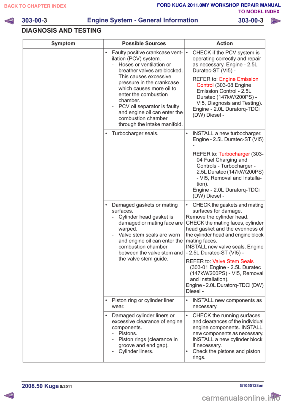
Action
Possible Sources
Symptom
• CHECK if the PCV system isoperating correctly and repair
as necessary. Engine - 2.5L
Duratec-ST (VI5) -
REFER to: Engine Emission
Control (303-08 Engine
Emission Control - 2.5L
Duratec (147kW/200PS) -
VI5, Diagnosis and Testing).
Engine - 2.0L Duratorq-TDCi
(DW) Diesel -
• Faulty positive crankcase vent-
ilation (PCV) system.
- Hoses or ventilation orbreather valves are blocked.
This causes excessive
pressure in the crankcase
which causes more oil to
enter the combustion
chamber.
- PCV oil separator is faulty and engine oil can enter the
combustion chamber
through the intake manifold.
• INSTALL a new turbocharger.Engine - 2.5L Duratec-ST (VI5)
-
REFER to: Turbocharger (303-
04 Fuel Charging and
Controls - Turbocharger -
2.5L Duratec (147kW/200PS)
- VI5, Removal and Installa-
tion).
Engine - 2.0L Duratorq-TDCi
(DW) Diesel -
• Turbocharger seals.
• CHECK the gaskets and matingsurfaces for damage.
Remove the cylinder head.
CHECK the mating faces, cylinder
head gasket and the evenness of
the cylinder head and engine block
mating faces.
INSTALL new valve seals. Engine
- 2.5L Duratec-ST (VI5) -
REFER to: Valve Stem Seals
(303-01 Engine - 2.5L Duratec
(147kW/200PS) - VI5, Removal
and Installation).
Engine - 2.0L Duratorq-TDCi (DW)
Diesel -
• Damaged gaskets or mating
surfaces.
- Cylinder head gasket isdamaged or mating face are
warped.
- Valve stem seals are worn and engine oil can enter the
combustion chamber
between the valve stem and
the valve stem guide.
• INSTALL new components asnecessary.
• Piston ring or cylinder liner
wear.
• CHECK the running surfacesand clearances of the individual
engine components. INSTALL
new components as necessary.
INSTALL a new cylinder block
if necessary.
• Check the pistons and piston rings.
• Damaged cylinder liners or
excessive clearance of engine
components.
- Pistons.
- Piston rings (clearance ingroove and end gap).
- Cylinder liners.
G1055128en2008.50 Kuga8/2011
303-00- 3
Engine System - General Information
303-00- 3
DIAGNOSIS AND TESTING
TO MODEL INDEX
BACK TO CHAPTER INDEX
FORD KUGA 2011.0MY WORKSHOP REPAIR MANUAL
Page 1523 of 2057
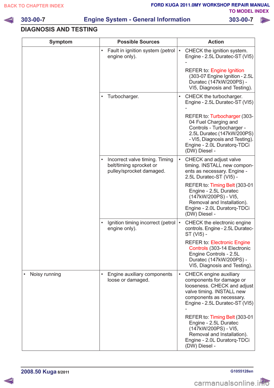
Action
Possible Sources
Symptom
• CHECK the ignition system.Engine - 2.5L Duratec-ST (VI5)
-
REFER to: Engine Ignition
(303-07 Engine Ignition - 2.5L
Duratec (147kW/200PS) -
VI5, Diagnosis and Testing).
• Fault in ignition system (petrol
engine only).
• CHECK the turbocharger.Engine - 2.5L Duratec-ST (VI5)
-
REFER to: Turbocharger (303-
04 Fuel Charging and
Controls - Turbocharger -
2.5L Duratec (147kW/200PS)
- VI5, Diagnosis and Testing).
Engine - 2.0L Duratorq-TDCi
(DW) Diesel -
• Turbocharger.
• CHECK and adjust valvetiming. INSTALL new compon-
ents as necessary. Engine -
2.5L Duratec-ST (VI5) -
REFER to: Timing Belt (303-01
Engine - 2.5L Duratec
(147kW/200PS) - VI5,
Removal and Installation).
Engine - 2.0L Duratorq-TDCi
(DW) Diesel -
• Incorrect valve timing. Timing
belt/timing sprocket or
pulley/sprocket damaged.
• CHECK the electronic enginecontrols. Engine - 2.5L Duratec-
ST (VI5) -
REFER to: Electronic Engine
Controls (303-14 Electronic
Engine Controls - 2.5L
Duratec (147kW/200PS) -
VI5, Diagnosis and Testing).
• Ignition timing incorrect (petrol
engine only).
• CHECK engine auxiliarycomponents for damage or
looseness. CHECK and adjust
valve timing. INSTALL new
components as necessary.
Engine - 2.5L Duratec-ST (VI5)
-
REFER to: Timing Belt (303-01
Engine - 2.5L Duratec
(147kW/200PS) - VI5,
Removal and Installation).
Engine - 2.0L Duratorq-TDCi
(DW) Diesel -
• Engine auxiliary components
loose or damaged.
• Noisy running
G1055128en2008.50 Kuga8/2011
303-00-
7
Engine System - General Information
303-00- 7
DIAGNOSIS AND TESTING
TO MODEL INDEX
BACK TO CHAPTER INDEX
FORD KUGA 2011.0MY WORKSHOP REPAIR MANUAL
Page 1542 of 2057
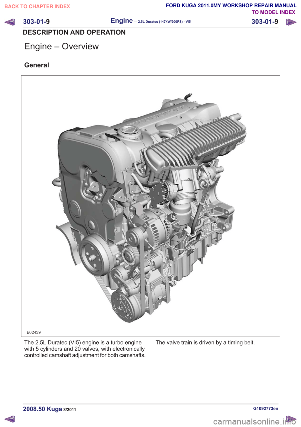
Engine – Overview
General
E62439
The 2.5L Duratec (VI5) engine is a turbo engine
with 5 cylinders and 20 valves, with electronically
controlled camshaft adjustment for both camshafts.The valve train is driven by a timing belt.
G1092773en2008.50 Kuga8/2011
303-01-
9
Engine— 2.5L Duratec (147kW/200PS) - VI5303-01-
9
DESCRIPTION AND OPERATION
TO MODEL INDEX
BACK TO CHAPTER INDEX
FORD KUGA 2011.0MY WORKSHOP REPAIR MANUAL
Page 1582 of 2057
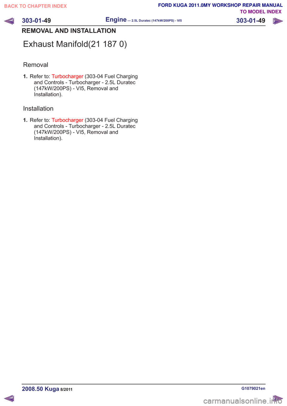
Exhaust Manifold(21 187 0)
Removal
1.Refer to: Turbocharger (303-04 Fuel Charging
and Controls - Turbocharger - 2.5L Duratec
(147kW/200PS) - VI5, Removal and
Installation).
Installation
1. Refer to: Turbocharger (303-04 Fuel Charging
and Controls - Turbocharger - 2.5L Duratec
(147kW/200PS) - VI5, Removal and
Installation).
G1079021en2008.50 Kuga8/2011
303-01- 49
Engine— 2.5L Duratec (147kW/200PS) - VI5303-01-
49
REMOVAL AND INSTALLATION
TO MODEL INDEX
BACK TO CHAPTER INDEX
FORD KUGA 2011.0MY WORKSHOP REPAIR MANUAL
Page 1673 of 2057
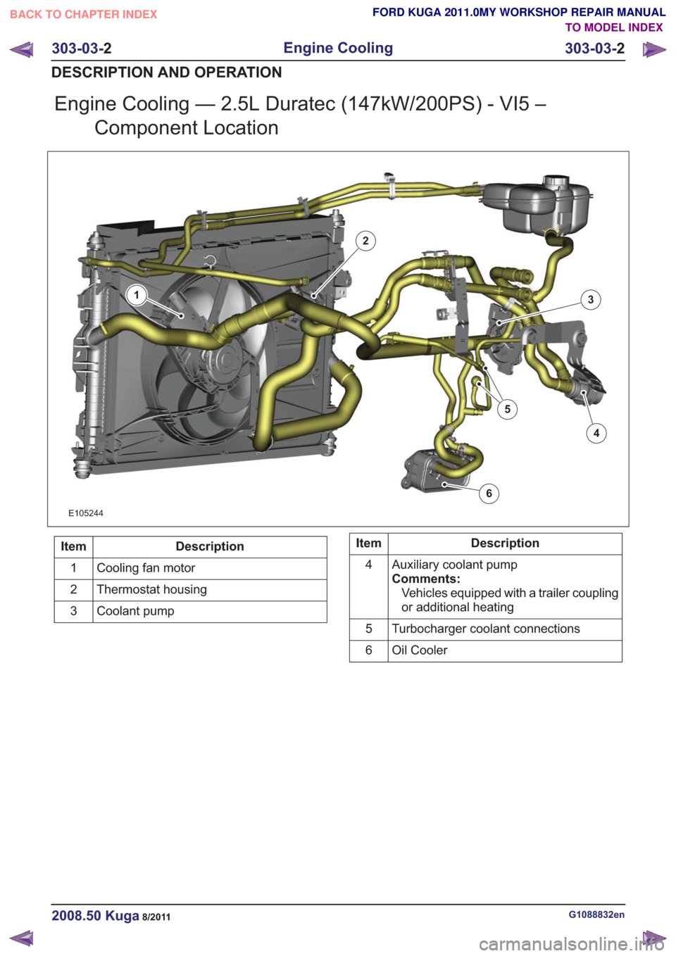
Engine Cooling — 2.5L Duratec (147kW/200PS) - VI5 –Component Location
E105244
1
2
3
4
5
6
Description
Item
Cooling fan motor
1
Thermostat housing
2
Coolant pump
3Description
Item
Auxiliary coolant pump
Comments:Vehicles equipped with a trailer coupling
or additional heating
4
Turbocharger coolant connections
5
Oil Cooler
6
G1088832en2008.50 Kuga8/2011
303-03- 2
Engine Cooling
303-03- 2
DESCRIPTION AND OPERATION
TO MODEL INDEX
BACK TO CHAPTER INDEX
FORD KUGA 2011.0MY WORKSHOP REPAIR MANUAL
Page 1717 of 2057
SECTION 303-04B Fuel Charging and Controls -
Turbocharger
— 2.5L Duratec (147kW/200PS) - VI5
VEHICLE APPLICATION:2008.50 Kuga
PA G E
CONTENTS
DESCRIPTION AND OPERATION
303-04B-2
Turbocharger (Component Location) ........................................................................\
..........
303-04B-4
Turbocharger (Overview) ........................................................................\
............................
303-04B-4
Turbocharger(s) ........................................................................\
..........................................
303-04B-5
Turbocharger (System Operation and Component Description) ........................................
303-04B-5
System Diagram ........................................................................\
.........................................
303-04B-6
System Operation ........................................................................\
.......................................
303-04B-6
Turbocharger(s) ........................................................................\
......................................
303-04B-6
Turbocharger boost pressure control ........................................................................\
......
303-04B-7
Recirculated air valve ........................................................................\
.............................
303-04B-7
Component Description ........................................................................\
..............................
303-04B-7
Wastegate control valve ........................................................................\
..........................
303-04B-7
Recirculated air valve ........................................................................\
.............................
DIAGNOSIS AND TESTING 303-04B-9
Turbocharger ........................................................................\
..............................................
303-04B-9
Inspection and Verification ........................................................................\
..........................
REMOVAL AND INSTALLATION 303-04B-11
(23 612 0)
Turbocharger ........................................................................\
..........................
303-04B-1
Fuel Charging and Controls - Turbocharger
—
2.5L Duratec (147kW/200PS) - VI5
303-04B- 1
.
TO MODEL INDEX
BACK TO CHAPTER INDEX
FORD KUGA 2011.0MY WORKSHOP REPAIR MANUAL
Page 1718 of 2057
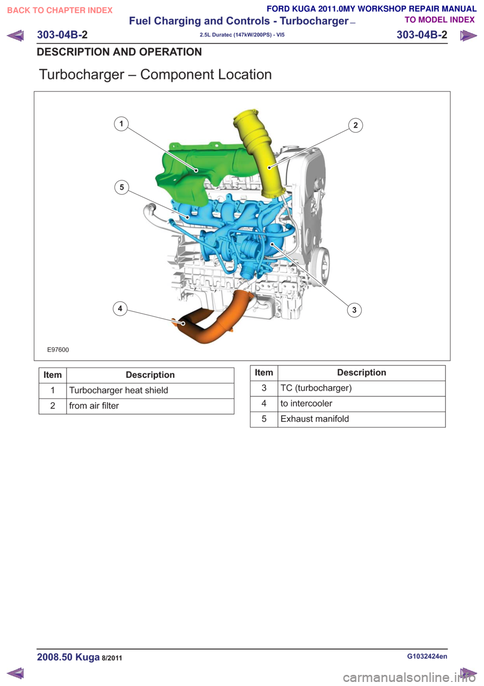
Turbocharger – Component Location
E97600
12
34
5
Description
Item
Turbocharger heat shield
1
from air filter
2Description
Item
TC (turbocharger)
3
to intercooler
4
Exhaust manifold
5
G1032424en2008.50 Kuga8/2011
303-04B- 2
Fuel Charging and Controls - Turbocharger
—
2.5L Duratec (147kW/200PS) - VI5
303-04B- 2
DESCRIPTION AND OPERATION
TO MODEL INDEX
BACK TO CHAPTER INDEX
FORD KUGA 2011.0MY WORKSHOP REPAIR MANUAL