Page 387 of 2057
SECTION 418-01 Module Configuration
VEHICLE APPLICATION:
2008.50 Kuga
PAGE
CONTENTS
GENERAL PROCEDURES
418-01-2
Module Configuration ..........................................................................................................
418-01-3
Programmable Module Installation ..................................................................................... 418-01-1
Module Configuration
418-01-1
.TO MODEL INDEX
BACK TO CHAPTER INDEX
FORD KUGA 2011.0MY WORKSHOP REPAIR MANUAL
Page 388 of 2057
Module Configuration
Activation
1.
Install the most up-to-date software version in
the integrated diagnostic system (IDS).
2. In IDS, select the "Module reprogramming"
submenu in the "Module programming" menu
tool box and then follow the instructions.
3. Transfer a new software version (if available)
to the powertrain control module (PCM) using
IDS, if a module-reprogramming of the PCM
may be required in the case of engine running
concerns.
4. Following installation of a wheel/tire
combination, for which the tire-tread
circumference does not correspond to that of
standard tires, the tire size must be changed in
the PCM using IDS. Therefore select the
"Programmable parameters" submenu and enter
the corresponding tire size under the "tire size"
menu item. G1158256en
2008.50 Kuga 8/2011 418-01-2
Module Configuration
418-01-2
GENERAL PROCEDURESTO MODEL INDEX
BACK TO CHAPTER INDEX
FORD KUGA 2011.0MY WORKSHOP REPAIR MANUAL
Page 389 of 2057

Programmable Module Installation
Activation
5.
Install the most up-to-date software version in
IDS.
6. If, before replacing a module, it was not possible
to read out the vehicle-specific data using the
integrated diagnostic system (IDS) (the module
to be replaced does not respond) then, during
programming of the new module, the
vehicle-specific data must be entered manually
via a selection list in IDS or via a code which
can be obtained from the Technical Hotline.
7. In order to program, select the "Install
programmable module" submenu in the "Module
programming" menu tool box and then follow
the instructions.
8. The following modules must be programmed
after replacement:
•
• Anti-lock braking system module (ABS)
• Audio system module (ACM)
• CD player (CDP)
• Driver's door control unit (D-DCU)
• Passenger's door control unit (P-DCU)
• Rear left door control unit (RL-DCU)
• Rear right door control unit (RR-DCU)
• Electrical power steering (EPS)
• Generic Display Module (GDM) (vehicles
with DVD navigation system with
touchscreen)
• Generic electronic module (GEM)
• Headlamp control module (HCM) (vehicles with gas discharge headlamps)
• Instrument cluster (IC)
• Navigation system (NAV) (vehicles with navigation system)
• Parking aid module(PAM)
• Powertrain control module (PCM)
• Restraint control module (RCM)
• Rear entertainment system module (RETM) (vehicles with rear seat entertainment
system)
9. In order to configure the PCM, select the
"Programmable parameters" submenu in the
"Module programming" menu tool box and then
follow the instructions.
10. For vehicles with anti-lock braking system and
electronic stability program, these must also be configured using IDS following replacement of
the lateral acceleration sensor, yaw rate sensor
or pressure sensor. Configuration is performed
in the "Programmable parameters" menu tool
box.
G1158258en
2008.50 Kuga 8/2011 418-01-3
Module Configuration
418-01-3
GENERAL PROCEDURESTO MODEL INDEX
BACK TO CHAPTER INDEX
FORD KUGA 2011.0MY WORKSHOP REPAIR MANUAL
Page 1422 of 2057

Description
Item
Front wheel sensor, right-hand side
8Description
Item
9 ESP switch
Testing the brakes on a roller dynamometer
- 4X4 vehicles only
On 4X4 vehicles a brake test on a roller
dynamometer must only be performed under the
following conditions.
• The brake test must not exceed a duration of 1 minute.
• Ignition key in position 0.
• The roller speed must not exceed 5 km/h.
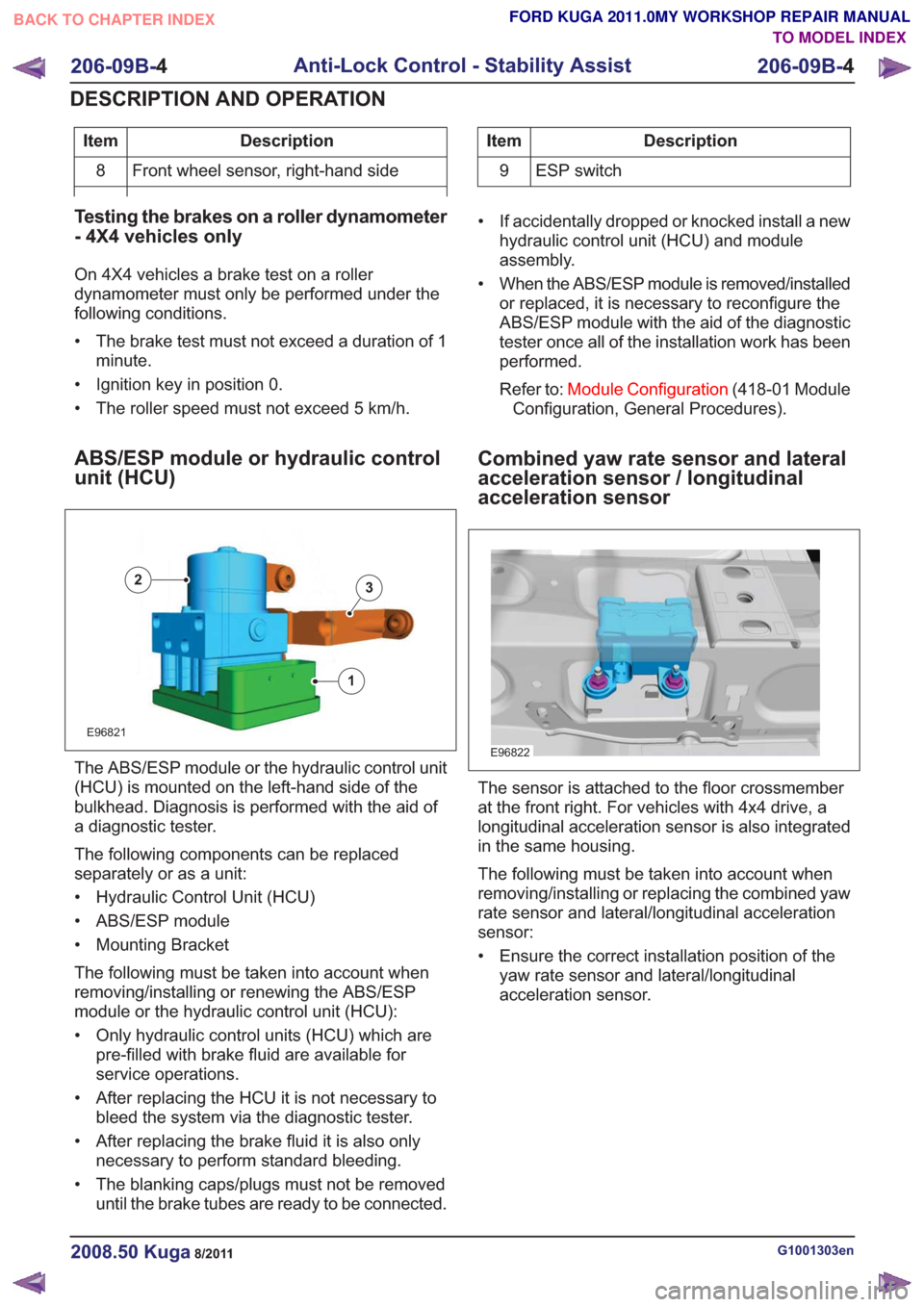
ABS/ESP module or hydraulic control
unit (HCU)
E96821
1
23
The ABS/ESP module or the hydraulic control unit
(HCU) is mounted on the left-hand side of the
bulkhead. Diagnosis is performed with the aid of
a diagnostic tester.
The following components can be replaced
separately or as a unit:
• Hydraulic Control Unit (HCU)
• ABS/ESP module
• Mounting Bracket
The following must be taken into account when
removing/installing or renewing the ABS/ESP
module or the hydraulic control unit (HCU):
• Only hydraulic control units (HCU) which are pre-filled with brake fluid are available for
service operations.
• After replacing the HCU it is not necessary to bleed the system via the diagnostic tester.
• After replacing the brake fluid it is also only necessary to perform standard bleeding.
• The blanking caps/plugs must not be removed until the brake tubes are ready to be connected. • If accidentally dropped or knocked install a new
hydraulic control unit (HCU) and module
assembly.
• When the ABS/ESP module is removed/installed or replaced, it is necessary to reconfigure the
ABS/ESP module with the aid of the diagnostic
tester once all of the installation work has been
performed.
Refer to: Module Configuration (418-01 Module
Configuration, General Procedures).
Combined yaw rate sensor and lateral
acceleration sensor / longitudinal
acceleration sensor
E96822
The sensor is attached to the floor crossmember
at the front right. For vehicles with 4x4 drive, a
longitudinal acceleration sensor is also integrated
in the same housing.
The following must be taken into account when
removing/installing or replacing the combined yaw
rate sensor and lateral/longitudinal acceleration
sensor:
• Ensure the correct installation position of the yaw rate sensor and lateral/longitudinal
acceleration sensor.
G1001303en2008.50 Kuga8/2011
206-09B- 4
Anti-Lock Control - Stability Assist
206-09B- 4
DESCRIPTION AND OPERATION
TO MODEL INDEX
BACK TO CHAPTER INDEX
FORD KUGA 2011.0MY WORKSHOP REPAIR MANUAL
Page 1463 of 2057

• Rubber bushes, electro-hydraulic power steeringpump
• Bracket #1
• Bracket #2
During removal and installation or renewal of
components of the electro-hydraulic power steering
pump, pay attention to the following:
• Before starting work to renew the electro-hydraulic power steering pump, the
program code of the electro-hydraulic power steering must be read out using the diagnostic
unit and noted.
• After the work to renew the electro-hydraulic power steering pump is completed, the
electro-hydraulic power steering must be
reconfigured using the diagnostic unit. For
further information, see: Module Configuration
(418-01 Module Configuration, General
Procedures).
• The electro-hydraulic power steering pump must be filled and vented as specified.
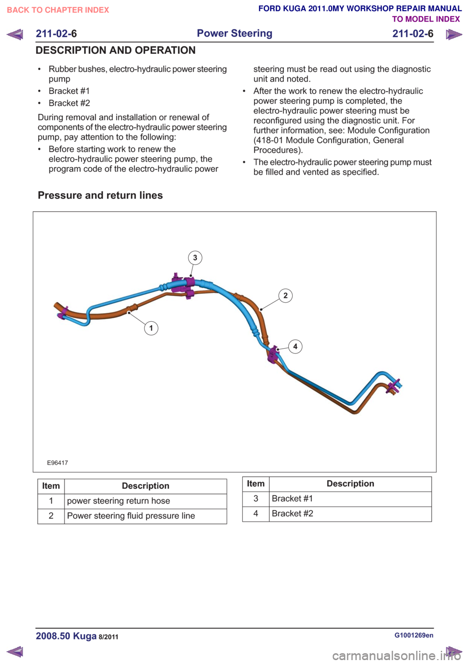
Pressure and return lines
E96417
1
2
3
4
Description
Item
power steering return hose
1
Power steering fluid pressure line
2Description
Item
Bracket #1
3
Bracket #2
4
G1001269en2008.50 Kuga8/2011
211-02- 6
Power Steering
211-02- 6
DESCRIPTION AND OPERATION
TO MODEL INDEX
BACK TO CHAPTER INDEX
FORD KUGA 2011.0MY WORKSHOP REPAIR MANUAL