2011 FORD KUGA trailer
[x] Cancel search: trailerPage 60 of 2057

Standard Workshop Practices
Vehicle in Workshop
When working on a vehicle in the workshop always
make sure that:
– the parking brake is applied or the wheels aresecurely chocked to prevent the vehicle moving
forwards or backwards.
– the key is removed from key operated hood locks before any work is carried out around the
front of the vehicle.
– if the engine is to be run, there is adequate ventilation, or an extraction hose to remove
exhaust fumes.
– there is adequate room to raise the vehicle and remove the wheels, if necessary.
– fender covers are always fitted if any work is to be carried out in the engine compartment.
– the battery is disconnected if working on the engine, underneath the vehicle, or if the vehicle
is raised.
CAUTION: When electric arc welding on a
vehicle, always disconnect the generator
wiring to prevent the possibility of a surge
of current causing damage to the internal
components of the generator.
– if using welding equipment on the vehicle, a suitable fire extinguisher is readily available.
Towing the Vehicle
WARNING: When the vehicle is being
towed, the ignition switch must be in
position II (steering lock released and
warning lamps illuminated). Only then will
the steering, turn signal lamps, horn and
stop lamps be operational. Failure to follow
these instructions may result in personal
injury.
NOTE: The removable towing eye (if equipped),
has a left-hand thread and must be fully tightened
before towing can commence.
When towing is necessary, the vehicle towing eyes
should be used. The rope must be securely
fastened to the towing eyes and must also be
attached to the other vehicle such that the rope will
not foul the bodywork.
When a vehicle with automatic transmission is
towed, the gear selector must be in position N (Neutral). Never tow a vehicle with automatic
transmission at a speed greater than 30 mph (50
km/h) or for a distance greater than 30 miles (50
km). If it is necessary to tow the vehicle a greater
distance, the drive wheels must be lifted clear off
the ground.
Alternatively the vehicle can be transported on a
low loader or a trailer.
Connecting a Slave Battery Using
Jumper Cables
WARNING: If the slave battery has recently
been charged and is gassing, cover the
vent plugs or covers with a damp cloth to
reduce the risk of explosion should arcing
occur when connecting the jumper cables.
Failure to follow these instructions may
result in personal injury.
CAUTIONS:
A discharged battery condition may have
been caused by an electrical short circuit.
If this condition exists there will be an
apparently live circuit on the vehicle even
when all normal circuits are switched off.
This can cause arcing when the jumper
cables are connected.
While it is not recommended that the
vehicle is jump started, it is recognized
that this may occasionally be the only
practical way to mobilize a vehicle. In such
an instance, the discharged battery must
be recharged immediately after jump
starting to avoid permanent damage.
– Always make sure that the jumper cables are adequate for the task. Heavy duty cables must
be used.
– Always make sure that the slave battery is of the same voltage as the vehicle battery. The
batteries must be connected in parallel.
– Always make sure that switched electric circuits are switched off before connecting jumper
cables. This reduces the risk of arcing occurring
when the final connection is made.
G17373en2008.50 Kuga8/2011
100-00- 54
General Information
100-00- 54
DESCRIPTION AND OPERATION
TO MODEL INDEX
BACK TO CHAPTER INDEX
FORD KUGA 2011.0MY WORKSHOP REPAIR MANUAL
Page 187 of 2057

Description
Item
Instrument Cluster
1
PCM (powertrain control module)
2
EHPS (electro-hydraulic power steering)
control module
3
Audio unit
4
GEM (generic electronic module)
5
RCM (restraints control module)
6
PATS transceiver
7 Description
Item
Steering wheel lock module
8
Left-hand steering column switch
9
Fuel level sensor
10
Washer water level warning lamp switch
11
Accelerator pedal position sensor
12
CPP (clutch pedal position) sensor/BPP
(brake pedal position) sensor
13
Lighting control switch
14
System Operation
Instrument Cluster
The instrument cluster contains analog displays
as well as warning and control lamps for displaying
the system status; in addiiton, there is an LCD
indicator field for driver information.
The instrument cluster receives the following
signals from the PCM via the high speed CAN
(controller area network) Bus (HS-CAN):
• Vehicle speed – The PCM receives the necessary signalsfrom the ABS (anti-lock brake system) wheel
sensors from the ABS control unit on the
HS-CAN.
• Engine Coolant Temperature
• Engine oil pressure.
• Engine speed
The instrument cluster receives the following
signals from the GEM via the medium speed CAN
Bus (MS-CAN):
• Ambient temperature
• Brake fluid level
• Handbrake control
• Door latch control
• Liftgate latch control
• High beam control
• Headlamp flasher control
• Direction indicator control
The fuel level signal is sent by the two fuel level
sensors in the fuel pumps in the semitrailer tank,
which is wired to the instrument cluster. The
sensors are connected in series, and the total
resistance is determined from the two individual resistors. The instrument cluster converts the raw
fuel level signal into a damped fuel level value.
The odometer shows the total distance travelled
by the vehicle and is based on the same signal as
is processed for the daily mileage counter. The
value is recorded by the instrument cluster and
stored in a protected EEPROM (Electronically
Erasable Programmable Read Only Memory) area.
This area is a memory protected against
manipulation. If the instrument cluster detects an
error in this memory area, e.g. through damage,
the driver is notified with the "Odometer error"
message.
Message center
The message center is operated using the left-hand
switch on the steering column.
The SET/RESET button is activated to select a
submenu and change the settings. If signal tones
have been activated, a short acoustic signal will
sound each time a button is pressed.
By turning the rotary switch, the different menu
displays can be scrolled through or a setting
selected.
In this display, the navigation system can also
display direction and distance information.
In addition, safety and warning messages can be
displayed in this system, such as "Coolant
overheating", "Engine system error" or "Washer
fluid level too low". In addition to a safety message,
a general warning light (red/yellow) lights up.
G1030770en
2008.50 Kuga 8/2011 413-01-4
Instrument Cluster
413-01-4
DESCRIPTION AND OPERATIONTO MODEL INDEX
BACK TO CHAPTER INDEX
FORD KUGA 2011.0MY WORKSHOP REPAIR MANUAL
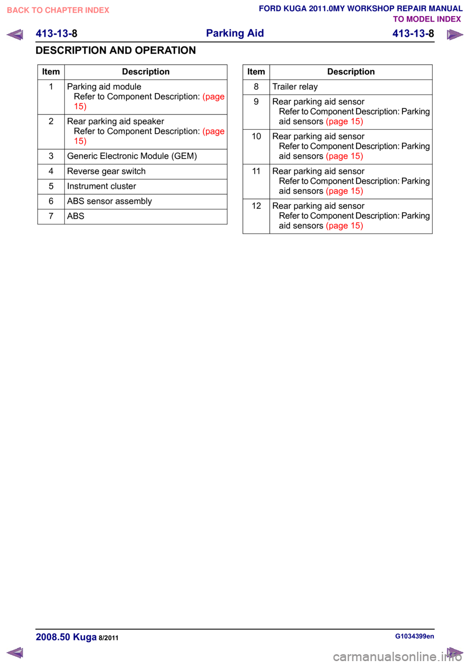
Page 207 of 2057

Description
Item
Parking aid moduleRefertoComponentDescription:(page
15)
1
Rear parking aid speakerRefertoComponentDescription:(page
15)
2
Generic Electronic Module (GEM)
3
Reverse gear switch
4
Instrument cluster
5
ABS sensor assembly
6
ABS7 Description
Item
Trailer relay
8
Rear parking aid sensorRefer to Component Description: Parking
aidsensors(page15)
9
Rear parking aid sensorRefer to Component Description: Parking
aidsensors(page15)
10
Rear parking aid sensorRefer to Component Description: Parking
aidsensors(page15)
11
Rear parking aid sensorRefer to Component Description: Parking
aidsensors(page15)
12 G1034399en
2008.50 Kuga 8/2011 413-13-8
Parking Aid
413-13-8
DESCRIPTION AND OPERATIONTO MODEL INDEX
BACK TO CHAPTER INDEX
FORD KUGA 2011.0MY WORKSHOP REPAIR MANUAL
Page 211 of 2057

Description
Item
Rear parking aid sensorRefer to Component Description: Parking
aid sensors (page ?)
7
Rear parking aid sensorRefer to Component Description: Parking
aid sensors (page ?)
8 Description
Item
Rear parking aid sensorRefer to Component Description: Parking
aid sensors (page ?)
9
steering angle sensor
10
Navigation device
11
System Operation
Parking Aid WARNING: It is the driver's responsibility
to stay alert during reversing procedures.
The system may fail to detect small
children or animals.
CAUTION: The driver is responsible for
detecting obstacles and judging the
distance between these and the vehicle.
The system may fail to detect some
hanging objects, barriers, narrow obstacles
or painted surfaces, which could damage
the vehicle. Always pay attention when
parking.
The parking aid provides an audible warning to the
driver if there are any obstacles in front of or behind
the vehicle during reverse parking maneuvers.
At low speeds, the parking aid module uses the
parking aid sensors to monitor the area around the
vehicle. If an object is detected within a monitored
area, the parking aid module emits a warning tone
using the respective parking aid speaker.
The rear parking aid is switched on with the
ignition. However, it is only enabled when reverse
gear is selected.
The front and rear parking aid is always switched
off when the ignition is switched on. It is switched
on when reverse gear is selected or if the parking
aid switch in the center console is actuated up to
a speed of 16 km/h.
The parking aid is switched off when the vehicle is
travelling forwards at more than 16 km/h or if the
parking aid switch in the center console is actuated
again.
When the parking aid module activates the system,
the parking aid switch LED is illuminated. If the
vehicle is only fitted with the rear parking aid, there
is no switch.
The parking aid sensors emit a series of ultrasonic
impulses and switch to receiver mode to receive the echo reflected by an obstacle within the
detection range. The received echo signals are
amplified and converted from an analog signal to
a digital signal by the sensor. The digital signal is
passed to the parking aid module and compared
with pre-programmed data stored in an EEPROM
within the module. The module calculates the
distance to the obstacle by measuring the time
taken between the emitted and received impulses.
If no objects are detected there are no further
warning tones. If an object is detected, repeated
audible tones are emitted from either parking aid
speaker(s) as appropriate. The time delay between
the tones decreases as the distance between the
object and the vehicle decreases, until at
approximately 250 mm (10 inches), the audible
tone becomes continuous.
If the distance between the obstacle and the
vehicle does not decrease, the warning tone
remains constant if the object has been detected
by an internal parking aid sensor. If the obstacle
was detected by an external sensor and the
distance remains unchanged, the warning tone
stops after 3 seconds.
The parking aid module continues to monitor the
distance and will resume the warning tones if a
decrease in distance is detected.
If a trailer is connected to the vehicle, a signal is
sent to the GEM (generic electronic module) via
the trailer relay. This signal is sent to the parking
aid module via the MS CAN bus. When the parking
aid module detects that a trailer is connected to
the vehicle, the rear parking aid sensors are
disabled to prevent constant warnings due to the
close proximity of the trailer.
G1034399en
2008.50 Kuga 8/2011 413-13-12
Parking Aid
413-13-12
DESCRIPTION AND OPERATIONTO MODEL INDEX
BACK TO CHAPTER INDEX
FORD KUGA 2011.0MY WORKSHOP REPAIR MANUAL
Page 228 of 2057

Parking Aid — Vehicles With: Rear Parking Aid
Refer to
Wiring Diagrams Section 413-13, for
schematic and connector information. General Equipment
Ford diagnostic equipment
Principles of Operation
NOTE: The rear parking aid system will be
de-activated when a Ford rear trailer tow module
is attached to the vehicle.
The ultrasonic parking aid system will default to
enabled when the ignition switch is turned to the
RUN position, the system is activated by selecting
reverse gear. The parking aid system will be
disabled if a fault is detected in one of the four rear
parking aid sensors, the parking aid speaker or the
parking aid module. An error tone approximately
3 seconds long will be emitted from the rear parking
aid speaker if a fault is detected. The rear parking
aid speaker will also sound for approximately 3
seconds if an error is detected at each ignition
cycle or if an error is detected when the system
has been activated.
Inspection and Verification
1. Verify the customer concern. 2. Visually inspect for obvious signs of electrical
damage.
Visual Inspection Chart Electrical
– Fuse(s)
– Wiring harness(s)
– Electrical connector(s)
– Battery junction box (BJB)
– Rear parking aid sensor(s)
– Rear parking aid speaker
– Parking aid module
3. If an obvious cause for an observed or reported concern is found, correct the cause (if possible)
before proceeding to the next step
4. If the cause is not visually evident, connect the Ford diagnostic equipment to the data link
connector (DLC) and select the vehicle system
to be tested from the diagnostic menu.
5. Retrieve the Diagnostic Trouble Code (DTC)s and refer to the DTC Index.
6. If no DTCs are retrieved or there is no communication with the module, proceed to the
Symptom Chart to continue diagnostics.
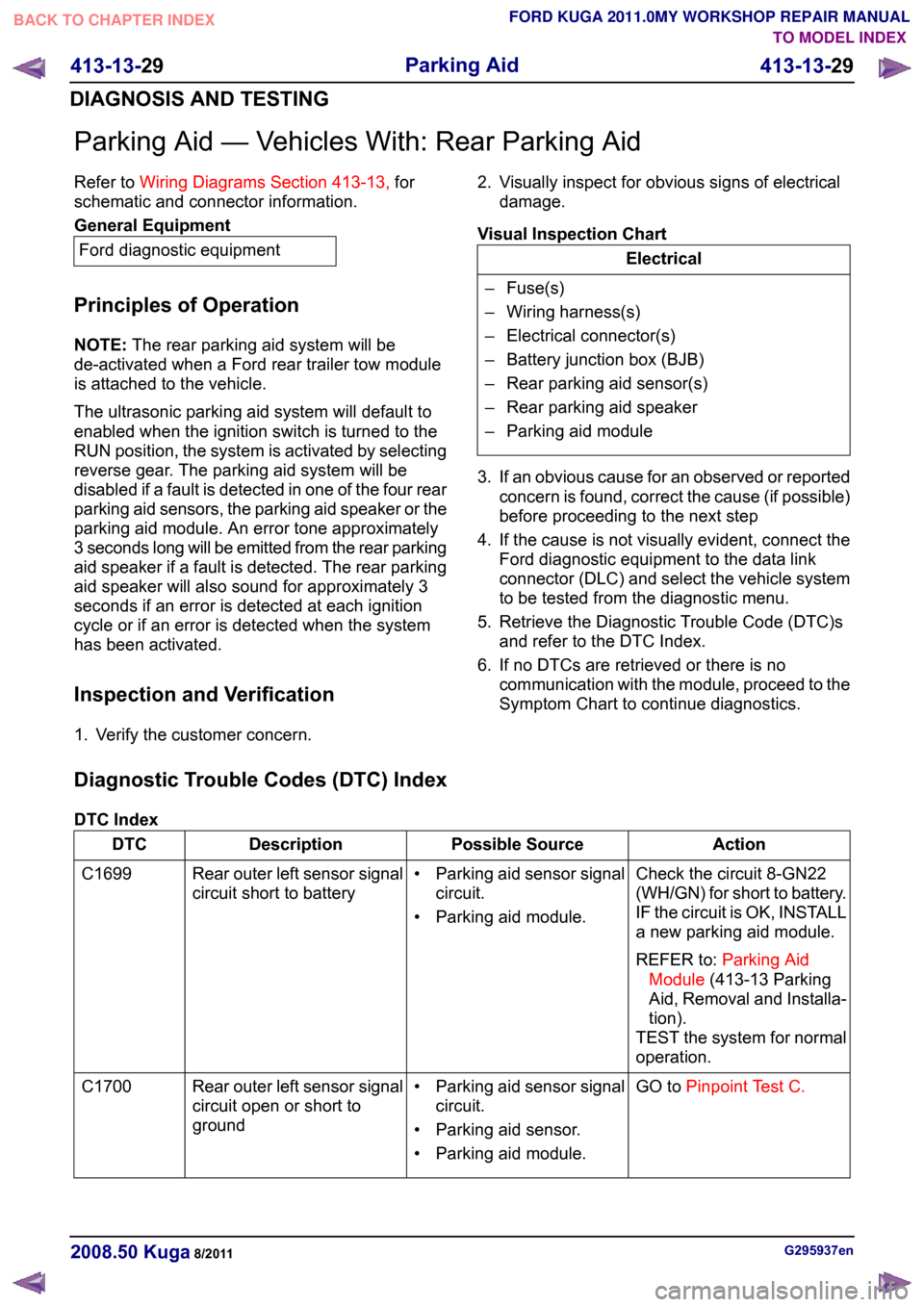
Diagnostic Trouble Codes (DTC) Index
DTC Index Action
Possible Source
Description
DTC
Check the circuit 8-GN22
(WH/GN) for short to battery.
IF the circuit is OK, INSTALL
a new parking aid module.
REFER to:Parking Aid
Module (413-13 Parking
Aid, Removal and Installa-
tion).
TEST the system for normal
operation.
• Parking aid sensor signal
circuit.
• Parking aid module.
Rear outer left sensor signal
circuit short to battery
C1699
GO toPinpoint Test C.
• Parking aid sensor signal
circuit.
• Parking aid sensor.
• Parking aid module.
Rear outer left sensor signal
circuit open or short to
ground
C1700 G295937en
2008.50 Kuga 8/2011 413-13-29
Parking Aid
413-13-29
DIAGNOSIS AND TESTINGTO MODEL INDEX
BACK TO CHAPTER INDEX
FORD KUGA 2011.0MY WORKSHOP REPAIR MANUAL
Page 336 of 2057

417-01-24
Stoplamps ...........................................................................................................................
417-01-24
Description of operation......................................................................................................
417-01-25
Inspection and Checking....................................................................................................
417-01-26
Turn Signal and Hazard Lamps..........................................................................................
417-01-26
Description of operation......................................................................................................
417-01-27
Inspection and Checking....................................................................................................
GENERAL PROCEDURES 417-01-29
Front Fog Lamp Adjustment...............................................................................................
417-01-30
Headlamp Adjustment........................................................................................................
REMOVAL AND INSTALLATION
417-01-32
Headlamp Switch................................................................................................................
417-01-34
Stoplamp Switch.................................................................................................................
417-01-35
Trailer Module.....................................................................................................................
417-01-36
Front Fog Lamp..................................................................................................................
417-01-37
Headlamp Assembly........................................................................................................... 417-01-2
Exterior Lighting
417-01-2
.TO MODEL INDEX
BACK TO CHAPTER INDEX
PAGE 2 OF 2 FORD KUGA 2011.0MY WORKSHOP REPAIR MANUAL
Page 369 of 2057

Trailer Module
Removal
1.
Refer to: Loadspace Trim Panel LH (501-05
Interior Trim and Ornamentation, Removal
and Installation).
2. Installation
1.
To install, reverse the removal procedure. G1158252en
2008.50 Kuga 8/2011 417-01-35
Exterior Lighting
417-01-35
REMOVAL AND INSTALLATIONTO MODEL INDEX
BACK TO CHAPTER INDEX
FORD KUGA 2011.0MY WORKSHOP REPAIR MANUALE122607
Page 1251 of 2057

Rear Drive Axle and Differential – System Operation andComponent Description
System Operation
General Information
The powertrain with all-wheel drive consists of the
following main components:
• engine
• transaxle with front axle differential
• transfer box
• halfshafts and driveshafts
• Haldex clutch
• rear axle differential
The Haldex clutch guarantees continuous variable
torque transmission to the rear axle under all
driving conditions. The Haldex clutch reacts
immediately and equally quickly with slow or fast
wheel slip.
A difference in angle of rotation of 90° between the
input and output shafts is required to build up
maximum pressure at the multi-plate clutch or to
transmit maximum torque.
The advantage of vehicles with all-wheel drive is
that they distribute the drive between all four
wheels. They therefore have a higher tractive
power. They feature improved cornering behaviour,
as the grip at all four wheels can be better utilised.
Thus, the wheels contribute to a greater degree
towards cornering stability.
The engine torque is transmitted from the transfer
box to the rear axle via a driveshaft. The driveshaft
is flange-mounted to the input side of the Haldex
clutch.
Driving situations
Pulling away and accelerating
• When pulling away and accelerating, as muchall-wheel drive as necessary must be available
immediately in the short-term. During
acceleration, the electronic system detects slip
at the front axle. This slip is counter-controlled
and thus the propulsive force optimally
distributed to the two axes.
Cornering • A sporty driving style, in particular dynamic
cornering, demands stable cornering behaviour.
The all-wheel system distributes the propulsive
force to all four wheels and by so doing boosts
the high cornering forces so that the vehicle
makes optimum contact with the road surface.
Snow and black ice
• Snow and black ice require particularly high grip. Under these conditions, the Haldex clutch
always distributes the propulsive force to the
axle with the better traction. The all-wheel
system reacts intelligently and quickly to all
driving situations.
Trailer operation
• When driving with a trailer, the trailer weight (support load) is transmitted to the rear axle via
the towbar. This reduces the load on the front
wheels, which means they can slip. The
electronic system detects this difference and
distributes most of the propulsive force to the
rear axle.
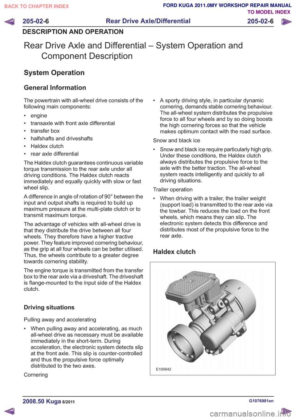
Haldex clutch
E100642
G1076981en2008.50 Kuga8/2011
205-02- 6
Rear Drive Axle/Differential
205-02- 6
DESCRIPTION AND OPERATION
TO MODEL INDEX
BACK TO CHAPTER INDEX
FORD KUGA 2011.0MY WORKSHOP REPAIR MANUAL