2011 FORD KUGA check oil
[x] Cancel search: check oilPage 54 of 2057

Accidental eye contact should be dealt with as per
normal first aid practices, by flushing the eyes with
an eye wash or clean cool water for 10 minutes,
after which medical attention should be obtained.
Remove and launder clothing which becomes
contaminated with the fluids. Do not place rags
contaminated with fluid in clothing pockets.
Wash thoroughly after completing operations where
skin exposure may have occurred.
It is important that personnel do not smoke, eat or
drink whilst handling the fluids or affected
transmissions. These measures are designed to
limit the risk from accidental ingestion.
Label any decanted fluid properly/use an equivalent
label to that on original product containers.
Clean up any spills promptly using an inert
absorbent and wash down contaminated surfaces
with detergent and water.
Dispose of any waste fluids safely as hazardous
waste.
Safety Data Sheets
Safety Data Sheets, which detail specific material
handling instructions and precautions are available
from the respective national sales company, and
via internet www.msds.ford.com.
Used Engine Oil
Prolonged and repeated contact with mineral oil
will result in the removal of natural fats from the
skin, leading to dryness, irritation and dermatitis.
In addition, used engine oil contains potentially
harmful contaminants, which may cause skin
cancer. Adequate means of skin protection and
washing facilities must be provided.
Do not employ used engine oils as lubricants or
for any application where appreciable skin contact
is likely to occur.
Environmental Precautions
Burning used engine oil in small space heaters or
boilers can be recommended only for units of
approved design. If in doubt check with the
appropriate local authority and manufacturer of
approved appliances.
Dispose of used oil and used oil filters through
authorized waste disposal contractors or licensedwaste disposal sites, or to the waste oil reclamation
trade. If in doubt, contact the relevant local
authority for advice on disposal facilities.
It is illegal to pour used oil on to the ground, down
sewers or drains, or into watercourses.
Noise
Some operations may produce high noise levels,
which could, in time, damage hearing. In these
cases, suitable ear protection must be worn.
Noise Insulation Materials
See
Foams, Fibre Insulation.
O-Rings (Fluoroelastomer)
SeeViton.
Paints
See also Solvents, Chemical Materials.
Highly flammable, flammable - observe No
Smoking policy
One Pack
Can contain harmful or toxic pigments, driers and
other components as well as solvents. Spraying
should be carried out only with adequate
ventilation.
Two Pack
Can also contain harmful and toxic unreacted
resins and resin hardening agents. The
manufacturers instructions should be followed. See
also Resin-based Adhesives and Isocyanate
Adhesives and Sealers under Adhesives and
Sealers.
Spraying should preferably be carried out in
exhausted ventilated booths removing vapor and
spray mists from the breathing zone. Individuals
working in booths should wear appropriate
respiratory protection. Those doing small-scale
repair work in the open workshop should wear
air-fed respirators.
G566527en2008.50 Kuga8/2011
100-00- 49
General Information
100-00- 49
DESCRIPTION AND OPERATION
TO MODEL INDEX
BACK TO CHAPTER INDEX
FORD KUGA 2011.0MY WORKSHOP REPAIR MANUAL
Page 63 of 2057

Road/Roller Testing
Road or roller testing may be carried out for various
reasons and a procedure detailing pre-test checks,
engine starting and stopping, pre-driving checks,
on-test checks and final checks to be completed
on completion of the test is given below.
Unless complete vehicle performance is being
checked, the full road test procedure need not be
carried out. Instead, those items particularly
relevant to the system(s) being checked can be
extracted.
Pre-Test Checks
WARNING: If the brake system hydraulic
fluid level is low, pedal travel is excessive
or a hydraulic leak is found, do not attempt
to road test the vehicle until the reason for
the low fluid level, excessive pedal travel
or hydraulic leak is found and rectified.
It is suggested that pre-test checks and functional
tests of those systems and circuits which affect the
safe and legal operations of the vehicle, such as
brakes, lights and steering, should always be
carried out before the road or roller test.
With the ignition switched off, check:
– the engine oil level.
– the engine coolant level.
– the tires, for correct pressure, compatible types and tread patterns, and wear within limits.
– that there is sufficient fuel in the tank to complete the test.
– all around the engine, transmission and under the vehicle for oil, coolant, hydraulic and fuel
leaks. Make a note of any apparent leaks and
wipe off the surrounding areas to make it easier
to identify the extent of the leak on completion
of the test.
Starting the Engine
NOTE: On initial drive away from cold and within
the first 1.5 km (1 mile), do not depress the
accelerator pedal beyond half travel until the
vehicle has attained a minimum speed of 25 km/h
(15 miles/h). Never operate at high engine speed
or with the accelerator pedal at full travel whilst the
engine is cold.
With the ignition switched off, check: – that the parking brake is applied.
– that the gear lever is in the neutral position.
– that all instrument gauges (except fuel gauge)
read zero.
With the ignition switched on, check:
– that the ignition controlled warning lamps are illuminated.
– that the engine temperature gauge registers a reading compatible with the engine temperature.
– that the fuel gauge registers a reading appropriate to the fuel level in the tank.
– the operation of the parking brake warning lamp and fluid level warning indicator.
Road or Roller Testing
CAUTION: If road testing, check the brake
operation while still traveling at low speed
before continuing with the test. If the
brakes pull to one side, or appear to be
otherwise faulty, do not continue with the
road test until the fault has been found and
rectified.
During the road or roller test, check:
– that the clutch pedal operation is not stiff or heavy.
– that the initial gear engagement is smooth and there is no evidence of clutch drag.
– that the parking brake control operates smoothly and releases quickly and completely.
– that the clutch takes up the drive smoothly, without slip or judder.
– that gear changing is smooth with no abnormal noises or vibrations from the transmission.
– the engine power output is satisfactory, full power is achieved, acceleration is smooth and
pedal operation is not stiff or heavy, and engine
speed returns to idle correctly.
– there is no excessive or abnormally colored smoke from the engine under normal driving,
heavy load or overrun conditions.
– that steering operation, including power steering (if equipped), is smooth, accurate, not
excessively heavy or with excessive free play
or vibration.
– that the steering does not pull to one side and self centers smoothly after cornering.
G17375en2008.50 Kuga8/2011
100-00- 58
General Information
100-00- 58
DESCRIPTION AND OPERATION
TO MODEL INDEX
BACK TO CHAPTER INDEX
FORD KUGA 2011.0MY WORKSHOP REPAIR MANUAL
Page 64 of 2057

– that the speedometer, coolant temperaturegauge and tachometer (if equipped) register the
correct readings and operate correctly.
– that the switches and controls operate smoothly and positively, warning and indicator lamps
operate correctly and the direction indicator
control self cancels when the steering is
returned to the straight ahead position.
– that the heating and ventilation systems operate correctly and effectively.
– the brake operation and efficiency.
Brake Testing
WARNING: When brake testing, avoid
breathing the fumes from hot brakes, this
may contain asbestos dust which is
hazardous to health. Failure to follow this
instruction may result in personal injury.
For additional information, refer to: Health
and Safety Precautions (100-00 General
Information, Description and Operation).
CAUTIONS:
Avoid brake testing on busy roads where
it may cause inconvenience or danger to
other road users.
Brake testing which includes heavy brake
applications should not be carried out with
new brake pads/discs or linings/drums
until the components have bedded-in. New
brake friction components will not reach
full efficiency until the bedding-in process
is complete.
Test the brakes at several speeds within the normal
operating range using both light and heavy pedal
pressure. Note any tendency to snatch, pull or
drag, and any undue delay in application or
release.
Allow the vehicle to coast and note any tendency
to pull to one side, or evidence that the brakes are
binding.
After stopping the vehicle (not immediately after a
period of heavy braking), carefully check the brake
temperature. A brake disc or brake drum that feels
hot or is appreciably hotter than the others,
indicates that the brake is binding.
After completion of the test, check for: – oil, coolant, hydraulic, air and fuel leaks.
– abnormal temperature of any moving
components or assemblies, for example wheel
hubs, transmission and axle, which might
indicate over tightness or lack of lubrication.
G17375en2008.50 Kuga8/2011
100-00- 59
General Information
100-00- 59
DESCRIPTION AND OPERATION
TO MODEL INDEX
BACK TO CHAPTER INDEX
FORD KUGA 2011.0MY WORKSHOP REPAIR MANUAL
Page 199 of 2057

Oil Change Indicator Reset
1.
Turn the ignition key to position II without
cranking the engine.
2. Simultaneously press and hold the accelerator
pedal and the brake pedal for approximately 15
seconds until the oil change reminder indicator
starts to flash or the "Service Oil Reset
Complete" message appears in the information
and message center (if equipped).
3. Release the pedals.
4. Check that the oil change reminder indicator
has turned off or that there is no "Service Oil"
message in the information and message center
(if equipped). If the oil change reminder indicator
is still illuminated or the "Service Oil" message
is still displayed, turn the ignition key to position
0 and repeat the procedure from Step 1. If it has
turned off or the "Service Oil" message has
disappeared, proceed to Step 5.
5. Turn the ignition key to position 0 and leave it
there for at least 2 minutes so that the
powertrain control module (PCM) fully powers
down and updates the non-volatile memory
(NVM) in the PCM.
6. Turn the ignition key to position II without
cranking the engine and check that the oil
change reminder indicator is not illuminated or
that there is no "Service Oil" message displayed.
7. Turn the ignition key to position 0. G898940en
2008.50 Kuga 8/2011 413-09-4
Warning Devices
413-09-4
GENERAL PROCEDURESTO MODEL INDEX
BACK TO CHAPTER INDEX
FORD KUGA 2011.0MY WORKSHOP REPAIR MANUAL
Page 1168 of 2057

3. If a new lower arm is installed it will benecessary to check and adjust the front wheel
alignment.
REFER to: Front Toe Adjustment (204-00
Suspension System - General Information,
General Procedures)
/ Rear Toe Adjustment (204-00 Suspension
System - General Information, General
Procedures).
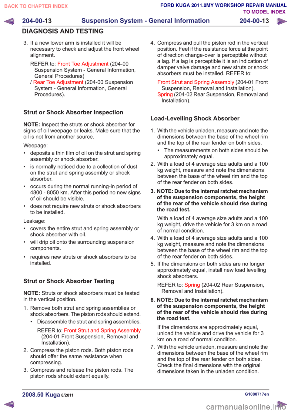
Strut or Shock Absorber Inspection
NOTE: Inspect the struts or shock absorber for
signs of oil weepage or leaks. Make sure that the
oil is not from another source.
Weepage:
• deposits a thin film of oil on the strut and spring assembly or shock absorber.
• is normally noticed due to a collection of dust on the strut and spring assembly or shock
absorber.
• occurs during the normal running-in period of 4800 - 8050 km. After this period no new signs
of oil should be visible.
• does not require new struts or shock absorbers to be installed.
Leakage:
• covers the entire strut and spring assembly or shock absorber with oil.
• will drip oil onto the surrounding suspension components.
• requires new struts or shock absorbers to be installed.
Strut or Shock Absorber Testing
NOTE: Struts or shock absorbers must be tested
in the vertical position.
1. Remove both strut and spring assemblies or shock absorbers. The piston rods should extend.
• Disassemble the strut and spring assemblies.
REFER to: Front Strut and Spring Assembly
(204-01 Front Suspension, Removal and
Installation).
2. Compress the piston rods. Both piston rods should offer the same resistance when
compressing.
3. Compress and release the piston rods. The piston rods should extent equally. 4. Compress and pull the piston rod in the vertical
position. Feel if the resistance force at the point
of direction change-over is perceptible without
a lag. If a lag is perceptible it is an indication of
damper valve damage and new struts or shock
absorbers must be installed. REFER to:
Front Strut and Spring Assembly (204-01 Front
Suspension, Removal and Installation),
Spring (204-02 Rear Suspension, Removal and
Installation).
Load-Levelling Shock Absorber
1. With the vehicle unladen, measure and note the dimensions between the base of the wheel rim
and the top of the rear fender on both sides.
• The measurements on both sides should be approximately equal.
2. With a load of 4 average size adults and a 100 kg weight, measure and note the dimensions
between the base of the wheel rim and the top
of the rear fender on both sides.
3. NOTE: Due to the internal ratchet mechanism of the suspension components, the height
of the rear of the vehicle should rise during
the road test.
With a load of 4 average size adults and a 100
kg weight, drive the vehicle for 3 km on a road
of normal condition.
4. With a load of 4 average size adults and a 100 kg weight, measure and note the dimensions
between the base of the wheel rim and the top
of the rear fender on both sides.
5. If the dimensions on both sides are no longer approximately equal, install new load levelling
shock absorbers.
REFER to: Spring(204-02 Rear Suspension,
Removal and Installation).
6. NOTE: Due to the internal ratchet mechanism of the suspension components, the height
of the rear of the vehicle should rise during
the road test.
If the dimensions are approximately equal,
unload the vehicle and drive the vehicle for 3
km on a road of normal condition.
7. With the vehicle unladen, measure and note the dimensions between the base of the wheel rim
and the top of the rear fender on both sides.
Check the final dimensions with the original
dimensions taken in the unladen condition.
G1080717en2008.50 Kuga8/2011
204-00- 13
Suspension System - General Information
204-00- 13
DIAGNOSIS AND TESTING
TO MODEL INDEX
BACK TO CHAPTER INDEX
FORD KUGA 2011.0MY WORKSHOP REPAIR MANUAL
Page 1262 of 2057

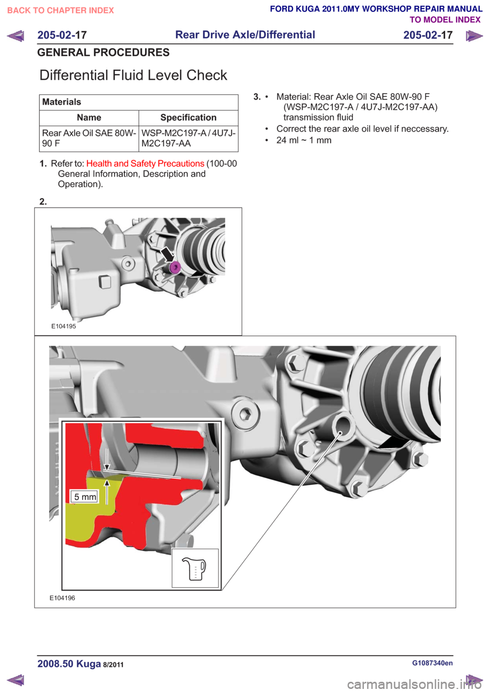
Differential Fluid Level Check
MaterialsSpecification
Name
WSP-M2C197-A / 4U7J-
M2C197-AA
Rear Axle Oil SAE 80W-
90 F
1. Refer to: Health and Safety Precautions (100-00
General Information, Description and
Operation).
2.
E104195
3. Material: Rear Axle Oil SAE 80W-90 F
(WSP-M2C197-A / 4U7J-M2C197-AA)
transmission fluid
•
• Correct the rear axle oil level if neccessary.
• 24ml~1mm
E104196
G1087340en2008.50 Kuga8/2011
205-02-
17
Rear Drive Axle/Differential
205-02- 17
GENERAL PROCEDURES
TO MODEL INDEX
BACK TO CHAPTER INDEX
FORD KUGA 2011.0MY WORKSHOP REPAIR MANUAL
Page 1264 of 2057

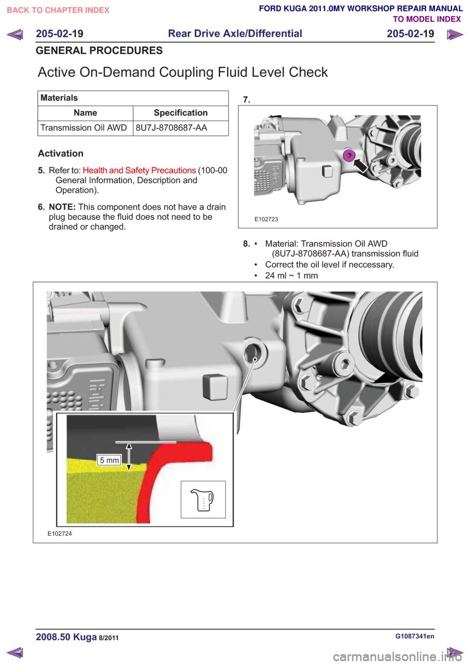
Active On-Demand Coupling Fluid Level Check
MaterialsSpecification
Name
8U7J-8708687-AA
Transmission Oil AWD
Activation
5. Refer to: Health and Safety Precautions (100-00
General Information, Description and
Operation).
6. NOTE: This component does not have a drain
plug because the fluid does not need to be
drained or changed. 7.
E102723
8.
Material: Transmission Oil AWD
(8U7J-8708687-AA) transmission fluid
•
• Correct the oil level if neccessary.
• 24ml~1mm
5mm5mm
E102724
G1087341en2008.50 Kuga8/2011
205-02-
19
Rear Drive Axle/Differential
205-02- 19
GENERAL PROCEDURES
TO MODEL INDEX
BACK TO CHAPTER INDEX
FORD KUGA 2011.0MY WORKSHOP REPAIR MANUAL
Page 1518 of 2057

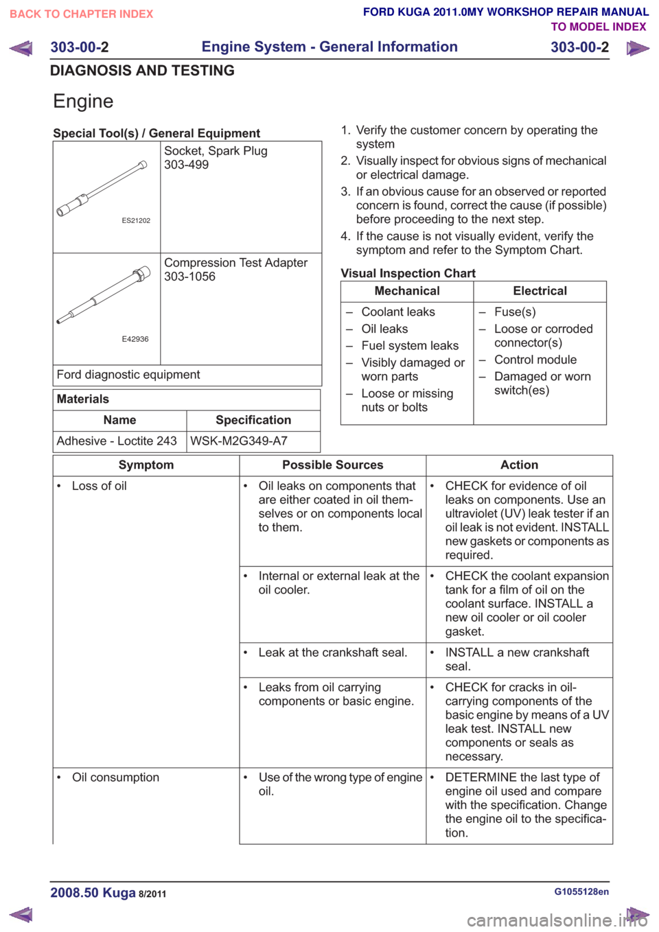
Engine
Special Tool(s) / General EquipmentSocket, Spark Plug
303-499
ES21202
Compression Test Adapter
303-1056
E42936
Ford diagnostic equipment
Materials
Specification
Name
WSK-M2G349-A7
Adhesive - Loctite 243 1. Verify the customer concern by operating the
system
2. Visually inspect for obvious signs of mechanical or electrical damage.
3. If an obvious cause for an observed or reported concern is found, correct the cause (if possible)
before proceeding to the next step.
4. If the cause is not visually evident, verify the symptom and refer to the Symptom Chart.
Visual Inspection Chart
Electrical
Mechanical
– Fuse(s)
– Loose or corrodedconnector(s)
– Control module
– Damaged or worn switch(es)
– Coolant leaks
– Oil leaks
– Fuel system leaks
– Visibly damaged or
worn parts
– Loose or missing nuts or bolts
Action
Possible Sources
Symptom
• CHECK for evidence of oilleaks on components. Use an
ultraviolet (UV) leak tester if an
oil leak is not evident. INSTALL
new gaskets or components as
required.
• Oil leaks on components that
are either coated in oil them-
selves or on components local
to them.
• Loss of oil
• CHECK the coolant expansiontank for a film of oil on the
coolant surface. INSTALL a
new oil cooler or oil cooler
gasket.
• Internal or external leak at the
oil cooler.
• INSTALL a new crankshaftseal.
• Leak at the crankshaft seal.
• CHECK for cracks in oil-carrying components of the
basic engine by means of a UV
leak test. INSTALL new
components or seals as
necessary.
• Leaks from oil carrying
components or basic engine.
• DETERMINE the last type ofengine oil used and compare
with the specification. Change
the engine oil to the specifica-
tion.
• Use of the wrong type of engine
oil.
• Oil consumption
G1055128en2008.50 Kuga8/2011
303-00-
2
Engine System - General Information
303-00- 2
DIAGNOSIS AND TESTING
TO MODEL INDEX
BACK TO CHAPTER INDEX
FORD KUGA 2011.0MY WORKSHOP REPAIR MANUAL