2011 FORD KUGA pistons
[x] Cancel search: pistonsPage 1254 of 2057
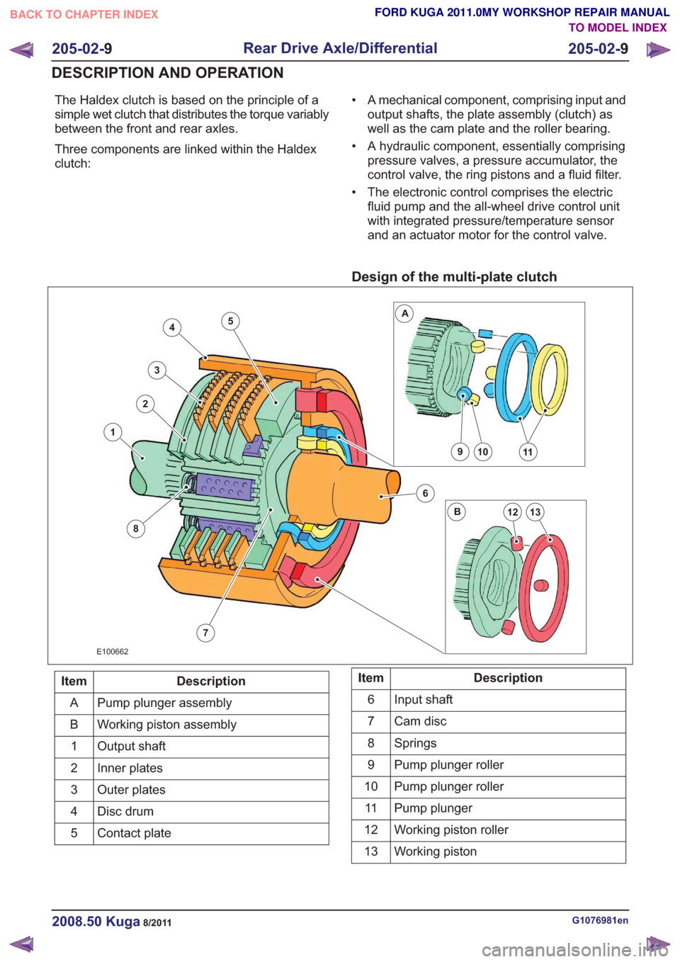
The Haldex clutch is based on the principle of a
simple wet clutch that distributes the torque variably
between the front and rear axles.
Three components are linked within the Haldex
clutch:• A mechanical component, comprising input and
output shafts, the plate assembly (clutch) as
well as the cam plate and the roller bearing.
• A hydraulic component, essentially comprising pressure valves, a pressure accumulator, the
control valve, the ring pistons and a fluid filter.
• The electronic control comprises the electric fluid pump and the all-wheel drive control unit
with integrated pressure/temperature sensor
and an actuator motor for the control valve.
Design of the multi-plate clutch
7
4
3
2
8
1
6
10911
13
A
B12
5
E100662
Description
Item
Pump plunger assembly
A
Working piston assembly
B
Output shaft
1
Inner plates
2
Outer plates
3
Disc drum
4
Contact plate
5Description
Item
Input shaft
6
Cam disc
7
Springs
8
Pump plunger roller
9
Pump plunger roller
10
Pump plunger
11
Working piston roller
12
Working piston
13
G1076981en2008.50 Kuga8/2011
205-02- 9
Rear Drive Axle/Differential
205-02- 9
DESCRIPTION AND OPERATION
TO MODEL INDEX
BACK TO CHAPTER INDEX
FORD KUGA 2011.0MY WORKSHOP REPAIR MANUAL
Page 1430 of 2057
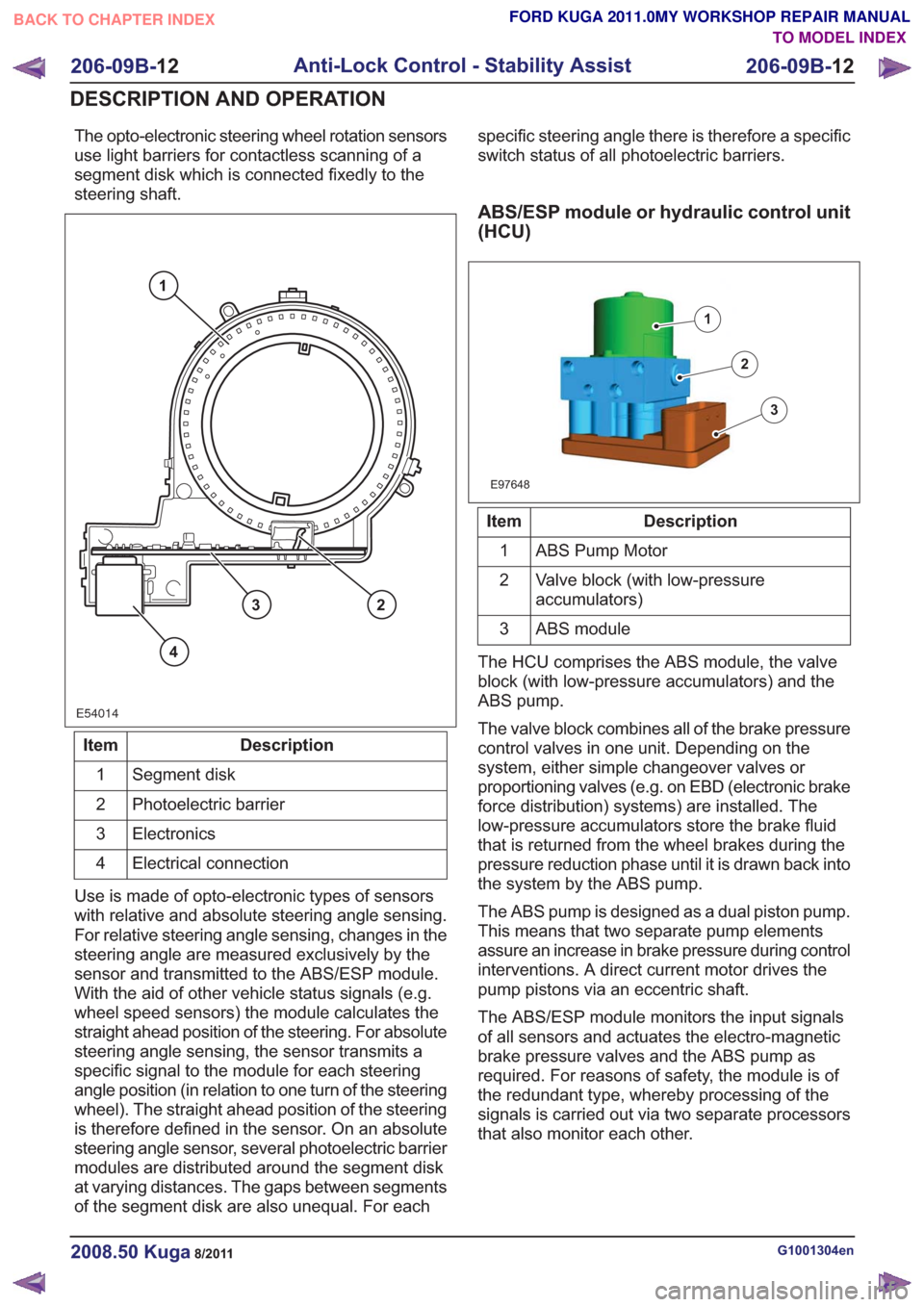
The opto-electronic steering wheel rotation sensors
use light barriers for contactless scanning of a
segment disk which is connected fixedly to the
steering shaft.
E54014
1
23
4
Description
Item
Segment disk
1
Photoelectric barrier
2
Electronics
3
Electrical connection
4
Use is made of opto-electronic types of sensors
with relative and absolute steering angle sensing.
For relative steering angle sensing, changes in the
steering angle are measured exclusively by the
sensor and transmitted to the ABS/ESP module.
With the aid of other vehicle status signals (e.g.
wheel speed sensors) the module calculates the
straight ahead position of the steering. For absolute
steering angle sensing, the sensor transmits a
specific signal to the module for each steering
angle position (in relation to one turn of the steering
wheel). The straight ahead position of the steering
is therefore defined in the sensor. On an absolute
steering angle sensor, several photoelectric barrier
modules are distributed around the segment disk
at varying distances. The gaps between segments
of the segment disk are also unequal. For each specific steering angle there is therefore a specific
switch status of all photoelectric barriers.
ABS/ESP module or hydraulic control unit
(HCU)
E97648
1
2
3
Description
Item
ABS Pump Motor
1
Valve block (with low-pressure
accumulators)
2
ABS module
3
The HCU comprises the ABS module, the valve
block (with low-pressure accumulators) and the
ABS pump.
The valve block combines all of the brake pressure
control valves in one unit. Depending on the
system, either simple changeover valves or
proportioning valves (e.g. on EBD (electronic brake
force distribution) systems) are installed. The
low-pressure accumulators store the brake fluid
that is returned from the wheel brakes during the
pressure reduction phase until it is drawn back into
the system by the ABS pump.
The ABS pump is designed as a dual piston pump.
This means that two separate pump elements
assure an increase in brake pressure during control
interventions. A direct current motor drives the
pump pistons via an eccentric shaft.
The ABS/ESP module monitors the input signals
of all sensors and actuates the electro-magnetic
brake pressure valves and the ABS pump as
required. For reasons of safety, the module is of
the redundant type, whereby processing of the
signals is carried out via two separate processors
that also monitor each other.
G1001304en2008.50 Kuga8/2011
206-09B- 12
Anti-Lock Control - Stability Assist
206-09B- 12
DESCRIPTION AND OPERATION
TO MODEL INDEX
BACK TO CHAPTER INDEX
FORD KUGA 2011.0MY WORKSHOP REPAIR MANUAL
Page 1519 of 2057
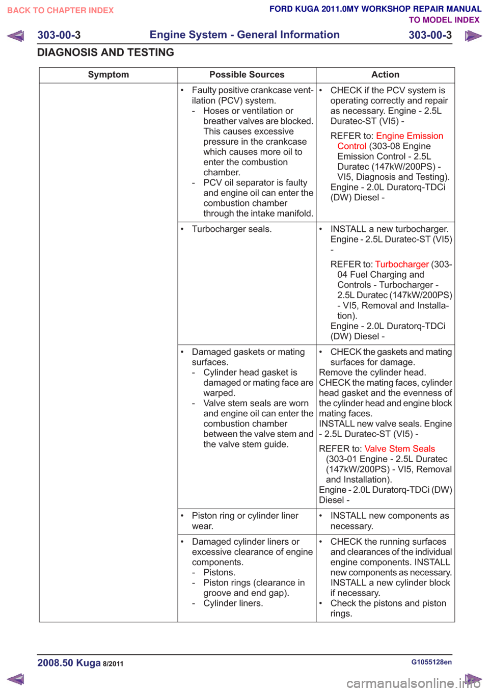
Action
Possible Sources
Symptom
• CHECK if the PCV system isoperating correctly and repair
as necessary. Engine - 2.5L
Duratec-ST (VI5) -
REFER to: Engine Emission
Control (303-08 Engine
Emission Control - 2.5L
Duratec (147kW/200PS) -
VI5, Diagnosis and Testing).
Engine - 2.0L Duratorq-TDCi
(DW) Diesel -
• Faulty positive crankcase vent-
ilation (PCV) system.
- Hoses or ventilation orbreather valves are blocked.
This causes excessive
pressure in the crankcase
which causes more oil to
enter the combustion
chamber.
- PCV oil separator is faulty and engine oil can enter the
combustion chamber
through the intake manifold.
• INSTALL a new turbocharger.Engine - 2.5L Duratec-ST (VI5)
-
REFER to: Turbocharger (303-
04 Fuel Charging and
Controls - Turbocharger -
2.5L Duratec (147kW/200PS)
- VI5, Removal and Installa-
tion).
Engine - 2.0L Duratorq-TDCi
(DW) Diesel -
• Turbocharger seals.
• CHECK the gaskets and matingsurfaces for damage.
Remove the cylinder head.
CHECK the mating faces, cylinder
head gasket and the evenness of
the cylinder head and engine block
mating faces.
INSTALL new valve seals. Engine
- 2.5L Duratec-ST (VI5) -
REFER to: Valve Stem Seals
(303-01 Engine - 2.5L Duratec
(147kW/200PS) - VI5, Removal
and Installation).
Engine - 2.0L Duratorq-TDCi (DW)
Diesel -
• Damaged gaskets or mating
surfaces.
- Cylinder head gasket isdamaged or mating face are
warped.
- Valve stem seals are worn and engine oil can enter the
combustion chamber
between the valve stem and
the valve stem guide.
• INSTALL new components asnecessary.
• Piston ring or cylinder liner
wear.
• CHECK the running surfacesand clearances of the individual
engine components. INSTALL
new components as necessary.
INSTALL a new cylinder block
if necessary.
• Check the pistons and piston rings.
• Damaged cylinder liners or
excessive clearance of engine
components.
- Pistons.
- Piston rings (clearance ingroove and end gap).
- Cylinder liners.
G1055128en2008.50 Kuga8/2011
303-00- 3
Engine System - General Information
303-00- 3
DIAGNOSIS AND TESTING
TO MODEL INDEX
BACK TO CHAPTER INDEX
FORD KUGA 2011.0MY WORKSHOP REPAIR MANUAL
Page 1525 of 2057
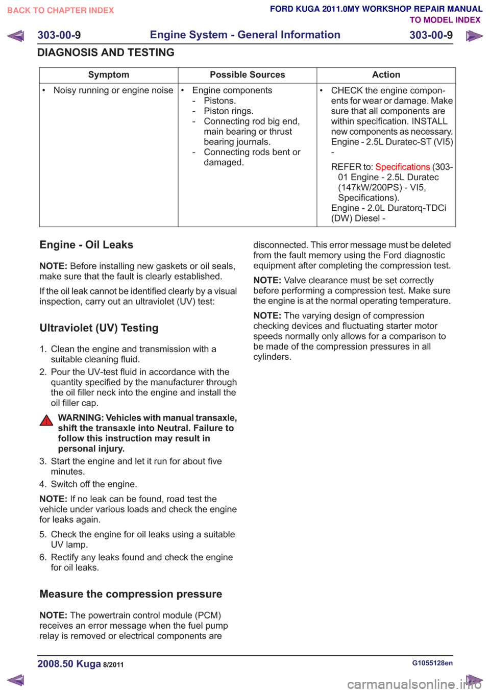
Action
Possible Sources
Symptom
• CHECK the engine compon-ents for wear or damage. Make
sure that all components are
within specification. INSTALL
new components as necessary.
Engine - 2.5L Duratec-ST (VI5)
-
REFER to: Specifications (303-
01 Engine - 2.5L Duratec
(147kW/200PS) - VI5,
Specifications).
Engine - 2.0L Duratorq-TDCi
(DW) Diesel -
• Engine components
- Pistons.
- Piston rings.
- Connecting rod big end,main bearing or thrust
bearing journals.
- Connecting rods bent or damaged.
• Noisy running or engine noise
Engine - Oil Leaks
NOTE:
Before installing new gaskets or oil seals,
make sure that the fault is clearly established.
If the oil leak cannot be identified clearly by a visual
inspection, carry out an ultraviolet (UV) test:
Ultraviolet (UV) Testing
1. Clean the engine and transmission with a suitable cleaning fluid.
2. Pour the UV-test fluid in accordance with the quantity specified by the manufacturer through
the oil filler neck into the engine and install the
oil filler cap.
WARNING: Vehicles with manual transaxle,
shift the transaxle into Neutral. Failure to
follow this instruction may result in
personal injury.
3. Start the engine and let it run for about five minutes.
4. Switch off the engine.
NOTE: If no leak can be found, road test the
vehicle under various loads and check the engine
for leaks again.
5. Check the engine for oil leaks using a suitable UV lamp.
6. Rectify any leaks found and check the engine for oil leaks.
Measure the compression pressure
NOTE: The powertrain control module (PCM)
receives an error message when the fuel pump
relay is removed or electrical components are disconnected. This error message must be deleted
from the fault memory using the Ford diagnostic
equipment after completing the compression test.
NOTE:
Valve clearance must be set correctly
before performing a compression test. Make sure
the engine is at the normal operating temperature.
NOTE: The varying design of compression
checking devices and fluctuating starter motor
speeds normally only allows for a comparison to
be made of the compression pressures in all
cylinders.
G1055128en2008.50 Kuga8/2011
303-00- 9
Engine System - General Information
303-00- 9
DIAGNOSIS AND TESTING
TO MODEL INDEX
BACK TO CHAPTER INDEX
FORD KUGA 2011.0MY WORKSHOP REPAIR MANUAL
Page 1547 of 2057
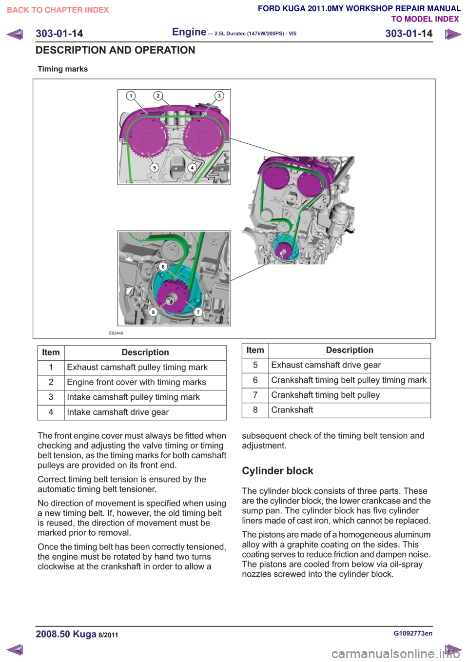
Timing marks
132
45
6
78
E62440
Description
Item
Exhaust camshaft pulley timing mark
1
Engine front cover with timing marks
2
Intake camshaft pulley timing mark
3
Intake camshaft drive gear
4Description
Item
Exhaust camshaft drive gear
5
Crankshaft timing belt pulley timing mark
6
Crankshaft timing belt pulley
7
Crankshaft
8
The front engine cover must always be fitted when
checking and adjusting the valve timing or timing
belt tension, as the timing marks for both camshaft
pulleys are provided on its front end.
Correct timing belt tension is ensured by the
automatic timing belt tensioner.
No direction of movement is specified when using
a new timing belt. If, however, the old timing belt
is reused, the direction of movement must be
marked prior to removal.
Once the timing belt has been correctly tensioned,
the engine must be rotated by hand two turns
clockwise at the crankshaft in order to allow a subsequent check of the timing belt tension and
adjustment.
Cylinder block
The cylinder block consists of three parts. These
are the cylinder block, the lower crankcase and the
sump pan. The cylinder block has five cylinder
liners made of cast iron, which cannot be replaced.
The pistons are made of a homogeneous aluminum
alloy with a graphite coating on the sides. This
coating serves to reduce friction and dampen noise.
The pistons are cooled from below via oil-spray
nozzles screwed into the cylinder block.
G1092773en2008.50 Kuga8/2011
303-01-
14
Engine— 2.5L Duratec (147kW/200PS) - VI5303-01-
14
DESCRIPTION AND OPERATION
TO MODEL INDEX
BACK TO CHAPTER INDEX
FORD KUGA 2011.0MY WORKSHOP REPAIR MANUAL
Page 1705 of 2057
Action
Possible Sources
Symptom
• CHECK for signs of contamina-tion such as strange odors from
the fuel tank.
• If contaminated fuel is found, DRAIN the complete fuel
system. FLUSH the fuel system
through with clean gasoline.
REFER to: Fuel Tank Draining
(310-00 Fuel System -
General Information, General
Procedures).
INSTALL a new fuel filter.
• INSPECT the fuel injectors. CLEAN the fuel injectors or
INSTALL a new set of injectors
as required only after the
checks have been carried out.
REFER to: Fuel Injectors (303-
04 Fuel Charging and
Controls - 2.5L Duratec
(147kW/200PS) - VI5,
Removal and Installation).
• INSTALL a new fuel rail.
REFER to: Fuel Rail(303-04
Fuel Charging and Controls -
2.5L Duratec (147kW/200PS)
- VI5, Removal and Installa-
tion).
• Incorrect or contaminated fuel.
• INSPECT for visible signs ofdamage or blockage. CLEAN,
REPAIR or INSTALL new parts
as necessary.
• Positive crankcase ventilation
(PCV) system.
• REMOVE the cylinder head.INSPECT the cylinder head,
pistons and cylinder bores for
signs of wear or damage.
REFER to: Cylinder Head (303-
01 Engine - 2.5L Duratec
(147kW/200PS) - VI5,
Removal and Installation).
• Worn or damaged valve
guide(s), piston ring(s), cylinder
bore(s), cylinder head or
gasket.
G1183441en2008.50 Kuga8/2011
303-04A- 14
Fuel Charging and Controls
— 2.5L Duratec (147kW/200PS) -
VI5
303-04A- 14
DIAGNOSIS AND TESTING
TO MODEL INDEX
BACK TO CHAPTER INDEX
FORD KUGA 2011.0MY WORKSHOP REPAIR MANUAL
Page 1710 of 2057
Action
Possible Sources
Symptom
• CHECK the valve timing.REFER to: Timing Belt (303-01
Engine - 2.5L Duratec
(147kW/200PS) - VI5,
Removal and Installation).
• Incorrect valve timing.
• REMOVE the cylinder head.INSPECT the cylinder head
and pistons for signs carbon
build up.
REFER to: Cylinder Head (303-
01 Engine - 2.5L Duratec
(147kW/200PS) - VI5,
Removal and Installation).
• Excessive carbon build up.
• INSPECT the engine compon-ents.
• Worn or damaged oil pump.
• Worn or damaged timing chain
or sprocket.
• Major mechanical engine failure.
• Carry out a full enginediagnosis using the guided
diagnostic menu in the Ford
diagnostic equipment.
• KS.
• Engine knock during accelera-
tion
• INSPECT the fuel injectors.CLEAN the fuel injectors or
INSTALL a new set of injectors
as required only after the
checks have been carried out.
REFER to: Fuel Injectors (303-
04 Fuel Charging and
Controls - 2.5L Duratec
(147kW/200PS) - VI5,
Removal and Installation).
• Fuel injectors.
• REFER to:Engine(303-00
Engine System - General
Information, Diagnosis and
Testing).
• Major mechanical engine
failure.
• CHECK the braking system.REFER to: Brake System (206-
00 Brake System - General
Information, Diagnosis and
Testing).
• Brakes binding.
• Excessive fuel consumption
• ADVISE the customer aboutthe effects of overloading the
vehicle and wind resistance on
the fuel consumption.
• Vehicle overloaded, or
excessive wind resistance (roof
racks, towing etc).
• INSTALL a new air cleanerelement.
• Air cleaner element blocked.
G1183441en2008.50 Kuga8/2011
303-04A-
19
Fuel Charging and Controls
— 2.5L Duratec (147kW/200PS) -
VI5
303-04A- 19
DIAGNOSIS AND TESTING
TO MODEL INDEX
BACK TO CHAPTER INDEX
FORD KUGA 2011.0MY WORKSHOP REPAIR MANUAL
Page 1794 of 2057
than to a change in the throttle valve position. The
ignition timing also changes much more quickly.
To keep the ignition point as close as possible to
the knock limit and so optimize the efficiency of the
engine, two KS are installed in the engine, which
pick up the mechanical vibrations of the engine
and convert them into an electrical signal for the
PCM.
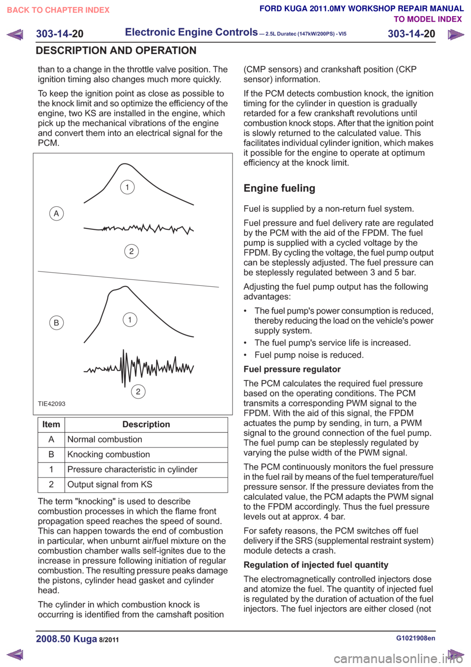
TIE42093
1
2
A
B1
2
Description
Item
Normal combustion
A
Knocking combustion
B
Pressure characteristic in cylinder
1
Output signal from KS
2
The term "knocking" is used to describe
combustion processes in which the flame front
propagation speed reaches the speed of sound.
This can happen towards the end of combustion
in particular, when unburnt air/fuel mixture on the
combustion chamber walls self-ignites due to the
increase in pressure following initiation of regular
combustion. The resulting pressure peaks damage
the pistons, cylinder head gasket and cylinder
head.
The cylinder in which combustion knock is
occurring is identified from the camshaft position (CMP sensors) and crankshaft position (CKP
sensor) information.
If the PCM detects combustion knock, the ignition
timing for the cylinder in question is gradually
retarded for a few crankshaft revolutions until
combustion knock stops. After that the ignition point
is slowly returned to the calculated value. This
facilitates individual cylinder ignition, which makes
it possible for the engine to operate at optimum
efficiency at the knock limit.
Engine fueling
Fuel is supplied by a non-return fuel system.
Fuel pressure and fuel delivery rate are regulated
by the PCM with the aid of the FPDM. The fuel
pump is supplied with a cycled voltage by the
FPDM. By cycling the voltage, the fuel pump output
can be steplessly adjusted. The fuel pressure can
be steplessly regulated between 3 and 5 bar.
Adjusting the fuel pump output has the following
advantages:
• The fuel pump's power consumption is reduced,
thereby reducing the load on the vehicle's power
supply system.
• The fuel pump's service life is increased.
• Fuel pump noise is reduced.
Fuel pressure regulator
The PCM calculates the required fuel pressure
based on the operating conditions. The PCM
transmits a corresponding PWM signal to the
FPDM. With the aid of this signal, the FPDM
actuates the pump by sending, in turn, a PWM
signal to the ground connection of the fuel pump.
The fuel pump can be steplessly regulated by
varying the pulse width of the PWM signal.
The PCM continuously monitors the fuel pressure
in the fuel rail by means of the fuel temperature/fuel
pressure sensor. If the pressure deviates from the
calculated value, the PCM adapts the PWM signal
to the FPDM accordingly. Thus the fuel pressure
levels out at approx. 4 bar.
For safety reasons, the PCM switches off fuel
delivery if the SRS (supplemental restraint system)
module detects a crash.
Regulation of injected fuel quantity
The electromagnetically controlled injectors dose
and atomize the fuel. The quantity of injected fuel
is regulated by the duration of actuation of the fuel
injectors. The fuel injectors are either closed (not
G1021908en2008.50 Kuga8/2011
303-14- 20
Electronic Engine Controls— 2.5L Duratec (147kW/200PS) - VI5303-14-
20
DESCRIPTION AND OPERATION
TO MODEL INDEX
BACK TO CHAPTER INDEX
FORD KUGA 2011.0MY WORKSHOP REPAIR MANUAL