2011 FORD KUGA Spark
[x] Cancel search: SparkPage 66 of 2057

Battery and Battery Charging Health and Safety Precautions
WARNINGS:
Batteries contain sulphuric acid, avoid
contact with skin, eyes or clothing. Wear
safety goggles when working near the
battery to protect against possible
splashing of the acid solution.
EYE CONTACT: If acid comes into contact
with the eyes, flush immediately with
plenty of running water for a minimum of
15 minutes. Seek immediate medical
attention.
SKIN CONTACT: If acid comes into contact
with the skin, flush immediately with plenty
of running water for a minimum of 15
minutes. Seek immediate medical attention.
SWALLOWED: If acid is swallowed, rinse
the mouth with plenty of water and then
drink plenty of water or milk. Do not induce
vomiting. Seek immediate medical
attention.
Batteries normally produce explosive
gases. Do not allow naked flames, sparks
or lighted substances to come near the
battery.
When charging the battery shield your face
and wear safety goggles. Provide adequate
ventilation.
CAUTION: Boost charging with excessive
current or voltage above 16 volts will
damage the battery.
G548994en2008.50 Kuga8/2011
100-00-61
General Information
100-00- 61
DESCRIPTION AND OPERATION
TO MODEL INDEX
BACK TO CHAPTER INDEX
FORD KUGA 2011.0MY WORKSHOP REPAIR MANUAL
Page 70 of 2057

Petrol and Petrol-Ethanol Fuel Systems Health and SafetyPrecautions
WARNINGS:
Fuel may not give adequate warning before
toxic or harmful effects arise.
Exposure to fuel can be harmful and can
cause severe health damage or death.
Extreme care must be exercised when
handling hot fluids. Always wash off spilled
fluids from affected areas of skin
immediately.
Highly flammable mixtures are always
present and may ignite when working on
fuel systems. Do not allow naked flames,
sparks or lighted substances to come near
fuel related components.
Fuel must not be used as a cleaning agent.
Keep fuel containers tightly closed, out of
direct sunlight and in a cool area. Keep
away from heat sources, ignition sources
and oxidizing agents.
SKIN CONTACT: Excessive or prolonged
skin contact with diesel fuel may cause
serious skin disorders including skin
cancer.
SKIN CONTACT: Fuel is mildly irritating to
the skin and may cause dermatitis due to
defatting effect. Remove contaminated
clothing. Wash affected areas of skin with
soap and water. Seek medical attention for
any persistent skin irritation or
abnormality. Wash contaminated clothing
before reuse.
EYE CONTACT: Fuel is mildly irritating to
the eyes. Flush with plenty of running
water, blinking as often as possible. Do not
force the eyelid open. Seek medical
attention for any persistent eye irritation
or abnormality.
SWALLOWED: Fuel is moderately toxic
and tends to foam on vomiting. If drawn
into the lungs, inflammation may develop.
Do not induce vomiting. If spontaneous
vomiting occurs place the victim in a
forward position to reduce the risk of fuel
being drawn into the lungs. Give nothing
by mouth. If breathing but unconscious,
place in the recovery position. If breathing has stopped, apply artificial respiration.
Seek immediate medical attention.
INHALED: Fuel is toxic to the respiratory
and other body systems. Exposure may
result in various symptoms including
drowsiness, unconsciousness or severe
health damage. Move a victim to fresh air.
Keep a victim warm and at rest. If
unconscious, place in the recovery
position. If not breathing, apply artificial
respiration. Give cardiac massage if
necessary. Seek immediate medical
attention.
CAUTIONS:
Fuel injection equipment is manufactured
to very precise tolerances and fine
clearances. It is essential that absolute
cleanliness is observed when working with
these components.
Make sure that the workshop area in which
the vehicle is being worked on is as clean
and as dust free as possible.
G548996en2008.50 Kuga8/2011
100-00- 64
General Information
100-00- 64
DESCRIPTION AND OPERATION
TO MODEL INDEX
BACK TO CHAPTER INDEX
FORD KUGA 2011.0MY WORKSHOP REPAIR MANUAL
Page 72 of 2057

Body Repair Health and Safety and General Precautions
General
Appropriate repair methods and carrying out repair
and paint jobs correctly is particularly important to
the operating safety of vehicles and the safety of
people.
WARNING: There is danger of injury
through:
• High voltage when electrical welding. – Do not perform welding work in a dampenvironment or on a wet substrate. Use
suitable insulation underneath.
• Welding spatter and UV radiation. – Wear protective clothing, gloves and weldingmask or welding goggles.
• Fire, explosion and hot surfaces in the work area.
– Always have a suitable fire extinguisheravailable when using welding or heating
equipment.
– Remove flammable substances from the danger area. Remove the fuel tank and fuel
pipes and hoses.
– Welding and grinding near the battery presents the danger of explosion. Remove
the battery before you start working.
– During paint work there is an increased danger of fire or explosion. Prevent any
sparks being created. Fire, open light and
smoking are forbidden.
– Always ventilate the workplace well and use an extraction system.
– Wear protective footwear made from anti-static material.
– Only use tools made of wood, brass or copper to clean stands and extraction ducts.
Do not use tools made of steel.
– Only fill or decant paint materials in a specially marked area. • Inhalation and/or absorption through the skin of
harmful substances.
– Welding fumes grinding dusts and solventvapours can be extremely harmful to the
health.
– Sealants, underbody protection and paint residues must not be burnt down with an
unshielded flame, as this will produce harmful
substances.
– Always ventilate the workplace well and use an extraction system.
– Wear protective clothing.
• Pyrotechnic components. – Disconnect the battery negative clamp andcover the battery terminal.
– Remove any airbag components.
• Noise – Cutting, grinding and alignment work cancause a noise level over 85 dB (A).
– Always wear ear protection.
• High Forces. – The various body areas are subject to veryhigh forces during realignment work. Should
any component suddenly become detached
during this process, there is a very great
danger of injury.
– Pulling chains and pulling shackles must be secured with arrester cables.
As well as these general instructions on the
dangers in body and paint shops, you must
observe:
• All valid local national and international regulations governing Health and Safety at Work
• Safety instructions of material equipment and tool manufacturers
For additional information, refer to: (100-00 General
Information) Solvents, Sealants and Adhesives (Description
and Operation),
Air Conditioning (A/C) System Health and Safety Precautions (Description and Operation),
Supplemental Restraint System (SRS) Health and Safety Precautions (Description and
Operation).
G963390en2008.50 Kuga8/2011
100-00- 67
General Information
100-00- 67
DESCRIPTION AND OPERATION
TO MODEL INDEX
BACK TO CHAPTER INDEX
FORD KUGA 2011.0MY WORKSHOP REPAIR MANUAL
Page 167 of 2057

reprogrammed. However, if the engine hasn't been
run since the last programmed start, the fuel-fired
booster heater will not start up the second time so
as to prevent the battery from being discharged.
The length of time required to pre-heat the vehicle
is calculated in the control unit of the fuel-fired
booster heater and is based on two temperature
values:
• Ambient air temperature: this message is taken
from the GEM via the CAN bus.
• Coolant temperature: this is determined via an internal sensor in the fuel-fired booster heater.
The maximum heating time is 30 minutes at an
outside air temperature of -10 °C or lower. The
heating time decreases proportionally with
increasing ambient temperature until the ambient
temperature is between +15 °C and +20 °C. Then
the minimum heating time is 10 minutes. The
parking heater is deactivated at temperatures
above +20 °C.
The sequence for a programmed start of the
booster heater is as follows:
• Two minutes before the start of the maximum heating time the driver information
system/instrument cluster sends an activation
message to the fuel-fired booster heater via the
CAN bus.
• The fuel-fired booster heater calculates the required heating time and, if necessary, sends
a delay request on the CAN bus.
• At the calculated time, the fuel-fired booster heater starts up. The conditions for start-up are:
engine not running and amount of fuel in the
fuel tank is above 14% of maximum.
• When the coolant temperature reaches +30 °C, the control unit of the fuel-fired booster heater
sends a request to switch on the passenger
compartment blower.
• Eight minutes after the programmed switch-off time, the booster heater stops heating mode
and starts a run-on operation to clean the
system's spark plugs.
• Ten minutes after the switch-off time, the post-cleaning operation is complete. The
additional ten minutes run-on time provides
some leeway in case the driver is late arriving.
After a programmed start-up of the booster heater
it is switched off again after the heating time has
elapsed (or if the fuel level in the fuel tank drops
below 8%). The booster heater stops within 2 minutes of the engine starting. This leaves enough
time to check whether the switch-on conditions for
boost heat mode have been met, thus preventing
the booster heater from having to switch off and
switch back on again. The heater can be switched
off manually at any time from the menu.
Whilst the fuel-fired booster heater is in additional
heating mode and/or parking heating mode, the
instrument cluster receives a fuel consumption
signal; this is used to re-calculate the vehicle's
remaining range and fuel consumption data.
Emergency shutoff
In the event of an accident in which the airbags
are deployed, the control unit of the fuel-fired
booster heater receives a message on the CAN
bus from the restraints control module (RCM).
When this message is received, the booster heater
system switches off immediately.
The booster heater control module deactivates the
system and does not respond to further messages
on the CAN bus. The booster heater control module
needs to be activated with WDS.
Component Description
Electric Booster Heater
The electric booster heater consists of three
individual heating elements, which are incorporated
into a single housing. It is controlled by the generic
electronic module (GEM), taking into account the
following factors:
Detailed illustration of fuel-fired heater
G1066982en
2008.50 Kuga 8/2011 412-02-14
Auxiliary Climate Control
412-02-14
DESCRIPTION AND OPERATIONTO MODEL INDEX
BACK TO CHAPTER INDEX
FORD KUGA 2011.0MY WORKSHOP REPAIR MANUALE97621
Page 263 of 2057

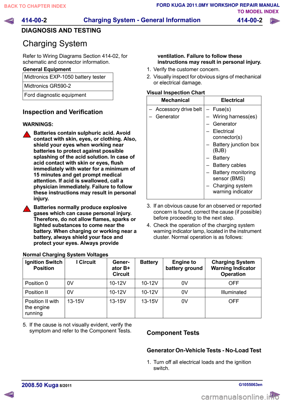
Charging System
Refer to Wiring Diagrams Section 414-02, for
schematic and connector information.
General Equipment
Midtronics EXP-1050 battery tester
Midtronics GR590-2
Ford diagnostic equipment
Inspection and Verification
WARNINGS: Batteries contain sulphuric acid. Avoid
contact with skin, eyes, or clothing. Also,
shield your eyes when working near
batteries to protect against possible
splashing of the acid solution. In case of
acid contact with skin or eyes, flush
immediately with water for a minimum of
15 minutes and get prompt medical
attention. If acid is swallowed, call a
physician immediately. Failure to follow
these instructions may result in personal
injury.
Batteries normally produce explosive
gases which can cause personal injury.
Therefore, do not allow flames, sparks or
lighted substances to come near the
battery. When charging or working near a
battery, always shield your face and
protect your eyes. Always provide
ventilation. Failure to follow these
instructions may result in personal injury.
1. Verify the customer concern.
2. Visually inspect for obvious signs of mechanical
or electrical damage.
Visual Inspection Chart Electrical
Mechanical
– Fuse(s)
– Wiring harness(es)
– Generator
– Electricalconnector(s)
– Battery junction box (BJB)
– Battery
– Battery cables
– Battery monitoring sensor (BMS)
– Charging system warning indicator
–
Accessory drive belt
– Generator
3. If an obvious cause for an observed or reported concern is found, correct the cause (if possible)
before proceeding to the next step.
4. Check the operation of the charging system warning indicator lamp, located in the instrument
cluster. Normal operation is as follows:
Normal Charging System Voltages Charging System
Warning Indicator Operation
Engine to
battery ground
Battery
Gener-
ator B+ Circuit
I Circuit
Ignition Switch
Position
OFF
0V
10-12V
10-12V
0V
Position 0
Illuminated
0V
10-12V
10-12V
0V
Position II
OFF
0V
13-15V
13-15V
13-15V
Position II with
the engine
running
5. If the cause is not visually evident, verify the symptom and refer to the Component Tests. Component Tests
Generator On-Vehicle Tests - No-Load Test
1. Turn off all electrical loads and the ignition
switch. G1055063en
2008.50 Kuga 8/2011 414-00-2
Charging System - General Information
414-00-2
DIAGNOSIS AND TESTINGTO MODEL INDEX
BACK TO CHAPTER INDEX
FORD KUGA 2011.0MY WORKSHOP REPAIR MANUAL
Page 270 of 2057

Battery Disconnect and Connect
Disconnect
WARNINGS:
Batteries normally produce explosive
gases which may cause personal injury,
therefore do not allow flames, sparks or
lighted substances to come near the
battery. When charging or working near
the battery always shield your face and
protect your eyes. Always provide
adequate ventilation. Failure to follow
these instructions may result in personal
injury.
The supplemental restraint system (SRS)
is active for a certain length of time after
the power supply has been disconnected.
Wait for a minimum of 3 minutes before
disconnecting or removing any SRS
components.
Audio unit key code saving devices must
not be used when working on
supplemental restraint or fuel systems.
When using these devices the vehicle
electrical system is still live but with a
reduced current flow. Failure to follow this
instruction may result in personal injury.
CAUTION: Make sure the engine is not
running before disconnecting the battery
ground cable to avoid damage to the
vehicle electrical system.
NOTE: Disconnecting the battery will erase fault
codes, drive values and customer data stored in
the modules.
NOTE: This procedure should be used to
disconnect the battery while carrying out repairs
that refer to the battery being disconnected.
1. Refer to: Battery and Battery Charging Health
and Safety Precautions (100-00 General
Information, Description and Operation).
2. Obtain and record the audio unit keycode and
preset radio frequencies. 3.
G1062389en
2008.50 Kuga 8/2011 414-01-2
Battery, Mounting and Cables
414-01-2
GENERAL PROCEDURESTO MODEL INDEX
BACK TO CHAPTER INDEX
FORD KUGA 2011.0MY WORKSHOP REPAIR MANUALE103137
Page 1518 of 2057

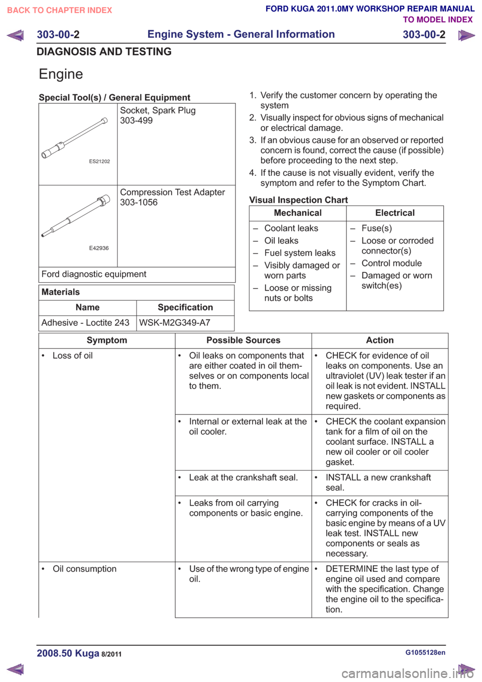
Engine
Special Tool(s) / General EquipmentSocket, Spark Plug
303-499
ES21202
Compression Test Adapter
303-1056
E42936
Ford diagnostic equipment
Materials
Specification
Name
WSK-M2G349-A7
Adhesive - Loctite 243 1. Verify the customer concern by operating the
system
2. Visually inspect for obvious signs of mechanical or electrical damage.
3. If an obvious cause for an observed or reported concern is found, correct the cause (if possible)
before proceeding to the next step.
4. If the cause is not visually evident, verify the symptom and refer to the Symptom Chart.
Visual Inspection Chart
Electrical
Mechanical
– Fuse(s)
– Loose or corrodedconnector(s)
– Control module
– Damaged or worn switch(es)
– Coolant leaks
– Oil leaks
– Fuel system leaks
– Visibly damaged or
worn parts
– Loose or missing nuts or bolts
Action
Possible Sources
Symptom
• CHECK for evidence of oilleaks on components. Use an
ultraviolet (UV) leak tester if an
oil leak is not evident. INSTALL
new gaskets or components as
required.
• Oil leaks on components that
are either coated in oil them-
selves or on components local
to them.
• Loss of oil
• CHECK the coolant expansiontank for a film of oil on the
coolant surface. INSTALL a
new oil cooler or oil cooler
gasket.
• Internal or external leak at the
oil cooler.
• INSTALL a new crankshaftseal.
• Leak at the crankshaft seal.
• CHECK for cracks in oil-carrying components of the
basic engine by means of a UV
leak test. INSTALL new
components or seals as
necessary.
• Leaks from oil carrying
components or basic engine.
• DETERMINE the last type ofengine oil used and compare
with the specification. Change
the engine oil to the specifica-
tion.
• Use of the wrong type of engine
oil.
• Oil consumption
G1055128en2008.50 Kuga8/2011
303-00-
2
Engine System - General Information
303-00- 2
DIAGNOSIS AND TESTING
TO MODEL INDEX
BACK TO CHAPTER INDEX
FORD KUGA 2011.0MY WORKSHOP REPAIR MANUAL
Page 1526 of 2057

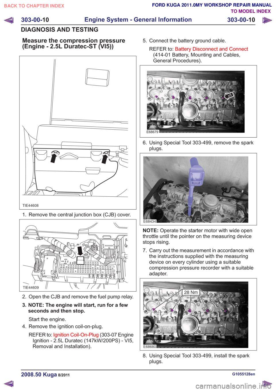
Measure the compression pressure
(Engine - 2.5L Duratec-ST (VI5))
TIE44608
1. Remove the central junction box (CJB) cover.
TIE44609
2. Open the CJB and remove the fuel pump relay.
3. NOTE: The engine will start, run for a fewseconds and then stop.
Start the engine.
4. Remove the ignition coil-on-plug.
REFER to: Ignition Coil-On-Plug (303-07 Engine
Ignition - 2.5L Duratec (147kW/200PS) - VI5,
Removal and Installation). 5. Connect the battery ground cable.
REFER to: Battery Disconnect and Connect
(414-01 Battery, Mounting and Cables,
General Procedures).
E68679
x5
6. Using Special Tool 303-499, remove the spark plugs.
E68434
NOTE: Operate the starter motor with wide open
throttle until the pointer on the measuring device
stops rising.
7. Carry out the measurement in accordance with the instructions supplied with the measuring
device on every cylinder using a suitable
compression pressure recorder with a suitable
adapter.
E68680
28 Nm
8. Using Special Tool 303-499, install the sparkplugs.
G1055128en2008.50 Kuga8/2011
303-00- 10
Engine System - General Information
303-00- 10
DIAGNOSIS AND TESTING
TO MODEL INDEX
BACK TO CHAPTER INDEX
FORD KUGA 2011.0MY WORKSHOP REPAIR MANUAL