2011 FORD KUGA sport mode
[x] Cancel search: sport modePage 22 of 2057

Description
Item
Steering wheel in straight ahead position
1
Steering column lock locked
2
Steering column lock unlocked
3
Turn the steering wheel to the 90° left
position
4Description
Item
Turn the steering wheel to the 90° right
position
5
Turn the steering wheel to the left-hand
end position
6
Turn the steering wheel to the right-hand
end position
7
E88971
6
3
12
4
5
78
9
11
10
Description
Item
3, 4, 5-door body style
1
Wagon body style
2Description
Item
Sports utility vehicle body style
3
Coupe body style
4
G955392en2008.50 Kuga8/2011
100-00- 22
General Information
100-00- 22
DESCRIPTION AND OPERATION
TO MODEL INDEX
BACK TO CHAPTER INDEX
FORD KUGA 2011.0MY WORKSHOP REPAIR MANUAL
Page 60 of 2057
Standard Workshop Practices
Vehicle in Workshop
When working on a vehicle in the workshop always
make sure that:
– the parking brake is applied or the wheels aresecurely chocked to prevent the vehicle moving
forwards or backwards.
– the key is removed from key operated hood locks before any work is carried out around the
front of the vehicle.
– if the engine is to be run, there is adequate ventilation, or an extraction hose to remove
exhaust fumes.
– there is adequate room to raise the vehicle and remove the wheels, if necessary.
– fender covers are always fitted if any work is to be carried out in the engine compartment.
– the battery is disconnected if working on the engine, underneath the vehicle, or if the vehicle
is raised.
CAUTION: When electric arc welding on a
vehicle, always disconnect the generator
wiring to prevent the possibility of a surge
of current causing damage to the internal
components of the generator.
– if using welding equipment on the vehicle, a suitable fire extinguisher is readily available.
Towing the Vehicle
WARNING: When the vehicle is being
towed, the ignition switch must be in
position II (steering lock released and
warning lamps illuminated). Only then will
the steering, turn signal lamps, horn and
stop lamps be operational. Failure to follow
these instructions may result in personal
injury.
NOTE: The removable towing eye (if equipped),
has a left-hand thread and must be fully tightened
before towing can commence.
When towing is necessary, the vehicle towing eyes
should be used. The rope must be securely
fastened to the towing eyes and must also be
attached to the other vehicle such that the rope will
not foul the bodywork.
When a vehicle with automatic transmission is
towed, the gear selector must be in position N (Neutral). Never tow a vehicle with automatic
transmission at a speed greater than 30 mph (50
km/h) or for a distance greater than 30 miles (50
km). If it is necessary to tow the vehicle a greater
distance, the drive wheels must be lifted clear off
the ground.
Alternatively the vehicle can be transported on a
low loader or a trailer.
Connecting a Slave Battery Using
Jumper Cables
WARNING: If the slave battery has recently
been charged and is gassing, cover the
vent plugs or covers with a damp cloth to
reduce the risk of explosion should arcing
occur when connecting the jumper cables.
Failure to follow these instructions may
result in personal injury.
CAUTIONS:
A discharged battery condition may have
been caused by an electrical short circuit.
If this condition exists there will be an
apparently live circuit on the vehicle even
when all normal circuits are switched off.
This can cause arcing when the jumper
cables are connected.
While it is not recommended that the
vehicle is jump started, it is recognized
that this may occasionally be the only
practical way to mobilize a vehicle. In such
an instance, the discharged battery must
be recharged immediately after jump
starting to avoid permanent damage.
– Always make sure that the jumper cables are adequate for the task. Heavy duty cables must
be used.
– Always make sure that the slave battery is of the same voltage as the vehicle battery. The
batteries must be connected in parallel.
– Always make sure that switched electric circuits are switched off before connecting jumper
cables. This reduces the risk of arcing occurring
when the final connection is made.
G17373en2008.50 Kuga8/2011
100-00- 54
General Information
100-00- 54
DESCRIPTION AND OPERATION
TO MODEL INDEX
BACK TO CHAPTER INDEX
FORD KUGA 2011.0MY WORKSHOP REPAIR MANUAL
Page 71 of 2057

Supplemental Restraint System (SRS) Health and SafetyPrecautions
WARNINGS:
Only qualified technicians are allowed to
work on pyrotechnic components.
INHALED: Exposure to pyrotechnic residue
may cause low blood pressure, severe
headache, irritation of mucous membranes,
fainting, shortness of breath or rapid pulse.
Move a victim to fresh air. Seek immediate
medical attention.
EYE CONTACT: Exposure to unburned
pyrotechnic residue may cause irritation,
burning and etching of the eyes. Flush
immediately with plenty of cold running
water for at least 15 minutes. Seek
immediate medical attention.
EYE CONTACT: Exposure to burned
pyrotechnic residue may cause irritation,
burning and etching of the eyes. Flush
immediately with diluted boric acid
solution. Seek immediate medical
attention.
SKIN CONTACT: Unburned pyrotechnic
residue may be rapidly absorbed through
the skin in toxic quantities. Wash
immediately with plenty of soap and water.
Seek medical attention.
SKIN CONTACT: Burned pyrotechnic
residue may be rapidly absorbed through
the skin in toxic quantities. Wash with
plenty of water. Do not use soap. Seek
medical attention.
SWALLOWED: Unburned pyrotechnic
residue is extremely toxic. If conscious
drink plenty of water then induce vomiting.
Seek immediate medical attention. If
unconscious, or in convulsions do not
attempt to induce vomiting or give
anything by mouth. Seek immediate
medical attention.
SWALLOWED: Burned pyrotechnic residue
is extremely toxic. Drink plenty of water
and seek immediate medical attention.
The deployment key must only be
accessible to authorized personnel.
Make sure that the deployment key remains
removed from the deployment equipment
except during deployment.
If permenantly disabling or enabling the
passenger air bag a new seat belt for
vehicles without or with a passenger air
bag must be installed.
Undeployed pyrotechnic components must
not be deployed in the vehicle.
Pyrotechnic components must be deployed
following local regulations.
Check thoroughly that no loose objects
can be spread during the deployment of
pyrotechnic components.
Pyrotechnic components must be
transported following local regulations.
Never carry out any electrical measurement
on disconnected, undeployed pyrotechnic
components.
Pyrotechnic components must not be
disassembled.
Pyrotechnic components are not
interchangeable between vehicles.
Always carry a live air bag module away
from the body with the air bag or trim cover
pointing upwards.
Live air bag modules must be placed in a
suitable cage when removed from the
vehicle. The air bag or trim cover must be
facing upwards.
Do not install a rearward facing child safety
seat to the passenger seat with an
activated passenger air bag.
CAUTIONS:
Pyrotechnic components must not be
subjected to temperatures higher than
110°C.
Never install aftermarket accessories to
the vehicle on or adjacent to the
supplemental restraint system module.
G548998en2008.50 Kuga8/2011
100-00- 65
General Information
100-00- 65
DESCRIPTION AND OPERATION
TO MODEL INDEX
BACK TO CHAPTER INDEX
FORD KUGA 2011.0MY WORKSHOP REPAIR MANUAL
Page 332 of 2057

Position the spring in the correct position (on
both sides) for the vehicle body style. 2. NOTE:
This step is only necessary when
installing a new component.
Remove the CD changer transportation retaining
clips. 3.
To install, reverse the removal procedure.
4. NOTE: This step is only necessary when
installing a new component.
Configure the CD changer by selecting the
Programmable Module Installation Routine.
General Equipment: Ford Diagnostic Equipment G1065585en
2008.50 Kuga 8/2011 415-01-36
Information and Entertainment System
415-01-36
REMOVAL AND INSTALLATIONTO MODEL INDEX
BACK TO CHAPTER INDEX
FORD KUGA 2011.0MY WORKSHOP REPAIR MANUAL12E91627 E91630
Page 1251 of 2057
Rear Drive Axle and Differential – System Operation andComponent Description
System Operation
General Information
The powertrain with all-wheel drive consists of the
following main components:
• engine
• transaxle with front axle differential
• transfer box
• halfshafts and driveshafts
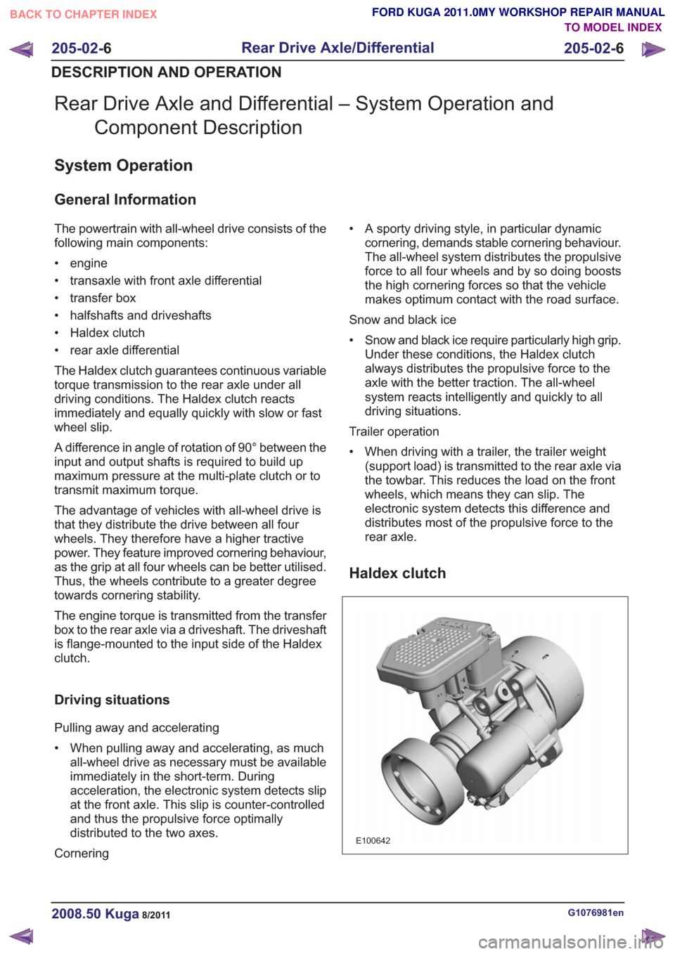
• Haldex clutch
• rear axle differential
The Haldex clutch guarantees continuous variable
torque transmission to the rear axle under all
driving conditions. The Haldex clutch reacts
immediately and equally quickly with slow or fast
wheel slip.
A difference in angle of rotation of 90° between the
input and output shafts is required to build up
maximum pressure at the multi-plate clutch or to
transmit maximum torque.
The advantage of vehicles with all-wheel drive is
that they distribute the drive between all four
wheels. They therefore have a higher tractive
power. They feature improved cornering behaviour,
as the grip at all four wheels can be better utilised.
Thus, the wheels contribute to a greater degree
towards cornering stability.
The engine torque is transmitted from the transfer
box to the rear axle via a driveshaft. The driveshaft
is flange-mounted to the input side of the Haldex
clutch.
Driving situations
Pulling away and accelerating
• When pulling away and accelerating, as muchall-wheel drive as necessary must be available
immediately in the short-term. During
acceleration, the electronic system detects slip
at the front axle. This slip is counter-controlled
and thus the propulsive force optimally
distributed to the two axes.
Cornering • A sporty driving style, in particular dynamic
cornering, demands stable cornering behaviour.
The all-wheel system distributes the propulsive
force to all four wheels and by so doing boosts
the high cornering forces so that the vehicle
makes optimum contact with the road surface.
Snow and black ice
• Snow and black ice require particularly high grip. Under these conditions, the Haldex clutch
always distributes the propulsive force to the
axle with the better traction. The all-wheel
system reacts intelligently and quickly to all
driving situations.
Trailer operation
• When driving with a trailer, the trailer weight (support load) is transmitted to the rear axle via
the towbar. This reduces the load on the front
wheels, which means they can slip. The
electronic system detects this difference and
distributes most of the propulsive force to the
rear axle.
Haldex clutch
E100642
G1076981en2008.50 Kuga8/2011
205-02- 6
Rear Drive Axle/Differential
205-02- 6
DESCRIPTION AND OPERATION
TO MODEL INDEX
BACK TO CHAPTER INDEX
FORD KUGA 2011.0MY WORKSHOP REPAIR MANUAL
Page 1800 of 2057
whereby the broadband HO2S emits a clear,
constant signal.
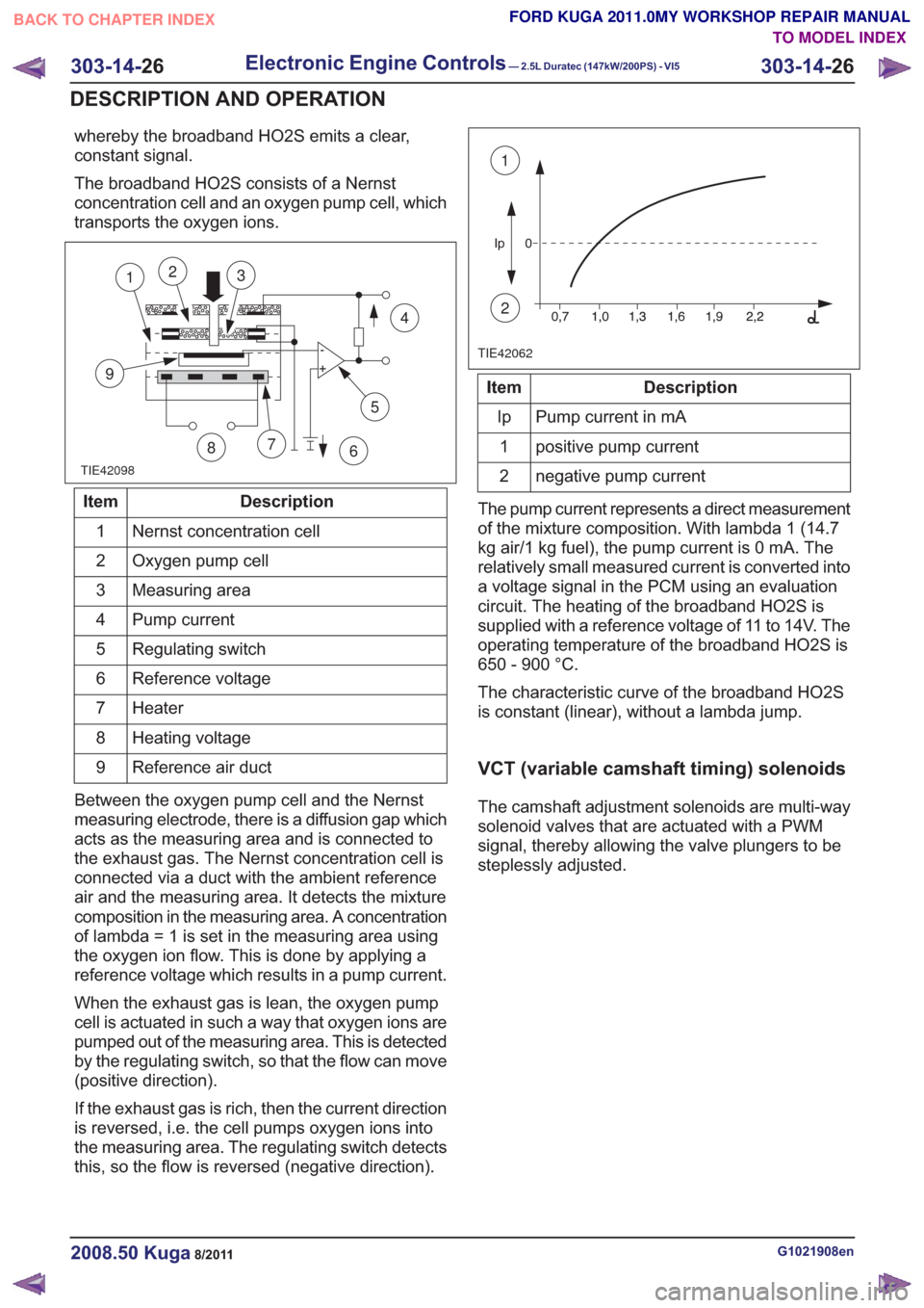
The broadband HO2S consists of a Nernst
concentration cell and an oxygen pump cell, which
transports the oxygen ions.
TIE42098
5
7
9
12
86
4
3
Description
Item
Nernst concentration cell
1
Oxygen pump cell
2
Measuring area
3
Pump current
4
Regulating switch
5
Reference voltage
6
Heater
7
Heating voltage
8
Reference air duct
9
Between the oxygen pump cell and the Nernst
measuring electrode, there is a diffusion gap which
acts as the measuring area and is connected to
the exhaust gas. The Nernst concentration cell is
connected via a duct with the ambient reference
air and the measuring area. It detects the mixture
composition in the measuring area. A concentration
of lambda = 1 is set in the measuring area using
the oxygen ion flow. This is done by applying a
reference voltage which results in a pump current.
When the exhaust gas is lean, the oxygen pump
cell is actuated in such a way that oxygen ions are
pumped out of the measuring area. This is detected
by the regulating switch, so that the flow can move
(positive direction).
If the exhaust gas is rich, then the current direction
is reversed, i.e. the cell pumps oxygen ions into
the measuring area. The regulating switch detects
this, so the flow is reversed (negative direction).
TIE42062
1
2
Description
Item
Pump current in mA
Ip
positive pump current
1
negative pump current
2
The pump current represents a direct measurement
of the mixture composition. With lambda 1 (14.7
kg air/1 kg fuel), the pump current is 0 mA. The
relatively small measured current is converted into
a voltage signal in the PCM using an evaluation
circuit. The heating of the broadband HO2S is
supplied with a reference voltage of 11 to 14V. The
operating temperature of the broadband HO2S is
650 - 900 °C.
The characteristic curve of the broadband HO2S
is constant (linear), without a lambda jump.
VCT (variable camshaft timing) solenoids
The camshaft adjustment solenoids are multi-way
solenoid valves that are actuated with a PWM
signal, thereby allowing the valve plungers to be
steplessly adjusted.
G1021908en2008.50 Kuga8/2011
303-14- 26
Electronic Engine Controls— 2.5L Duratec (147kW/200PS) - VI5303-14-
26
DESCRIPTION AND OPERATION
TO MODEL INDEX
BACK TO CHAPTER INDEX
FORD KUGA 2011.0MY WORKSHOP REPAIR MANUAL
Page 1823 of 2057
307-01-29
Automatic transmission, selector lever in position "D". ...................................................
307-01-29
Sport mode, selector lever in position "S" .......................................................................
307-01-29
Changing gear in select-shift mode........................................................................\
........
307-01-30
Selector lever from 'N' to 'R' position ........................................................................\
......
307-01-30
Self-test and Diagnosis ........................................................................\
...........................
307-01-30
Temperature controlled torque converter lockup ............................................................
307-01-30
Slip locking ........................................................................\
..............................................
307-01-30
Hill climbing ........................................................................\
.............................................
307-01-31
Downhill driving ........................................................................\
.......................................
307-01-31
Hill-hold function ........................................................................\
.....................................
307-01-31
Altitude correction ........................................................................\
...................................
307-01-31
Selector lever lock ........................................................................\
..................................
307-01-31
Shifting from P into another transmission range .............................................................
307-01-31
Shifting from N into another transmission range .............................................................
307-01-31
Power flow through the transmission ........................................................................\
......
307-01-31
Clutches and brakes ........................................................................\
...............................
307-01-33
Position P (park) ........................................................................\
.....................................
307-01-34
Position N (neutral) ........................................................................\
.................................
307-01-35
Position D, 1st gear........................................................................\
................................
307-01-36
Position D, 2nd gear ........................................................................\
...............................
307-01-37
Position D, 3rd gear ........................................................................\
................................
307-01-38
Position D, 4th gear ........................................................................\
................................
307-01-39
Position D, 5th gear ........................................................................\
................................
307-01-40
Position R (reverse) ........................................................................\
................................
307-01-41
Service instructions ........................................................................\
.................................
307-01-41
Towing procedure ........................................................................\
...................................
307-01-42
Reset adaptation data ........................................................................\
.............................
307-01-42
Limp home mode ........................................................................\
....................................
307-01-42
Component Description ........................................................................\
..............................
Tasks of the electronic components ........................................................................\
........
307-01-44
Input signals ........................................................................\
............................................
307-01-45
Output signals ........................................................................\
.........................................
Control valve assembly ........................................................................\
...........................
Shift solenoids S1 - S5 ........................................................................\
...........................
PWM-
solenoid valve – TCC (SLU) ........................................................................\
........
PWM solenoid valve – shift pressure (SLS) ...................................................................
PWM solenoid valve for main line pressure (SLT) ..........................................................
307-01-52
Installation position ........................................................................\
.................................
Operation ........................................................................\
................................................
Selector lever with integrated select-shift switch module ...............................................
Oil pump ........................................................................\
..................................................
Torque converter with TCC ........................................................................\
.....................
The TSS sensor ........................................................................\
......................................
The OSS sensor ........................................................................\
.....................................
The TFT sensor ........................................................................\
......................................
The TR sensor ........................................................................\
........................................
GENERAL PROCEDURES
T ransmission Fluid Level Check ........................................................................\
.................
307-01-63
T ransmission Fluid Drain and Refill ........................................................................\
............
REMOVAL AND INSTALLATION 307-01-67
Halfshaft Seal LH ........................................................................\
........................................
307-01-68
Halfshaft Seal RH........................................................................\
.......................................
307-01-69
Main Control Valve Body ........................................................................\
............................
307-01-2
Automatic Transmission/Transaxle
— Vehicles With:
5-Speed Automatic Transaxle - AW55 AWD
307-01- 2
.
TO MODEL INDEX
BACK TO CHAPTER INDEX
307-01-42
307-01-49
307-01-52 307-01-47
307-01-45
307-01-50
307-01-51
307-01-53
307-01-55
307-01-54
307-01-56
307-01-57
307-01-58
307-01-61 307-01-60
PAGE 2 OF 3 FORD KUGA 2011.0MY WORKSHOP REPAIR MANUAL
Page 1830 of 2057
1
234
5
6
8
9
7
E112582
Description
Item
Gear selector mechanism
1
Selector lever cable guide
2
Selector cable
3
Damper weight
4Description
Item
Adjusting mechanism for selector lever
cable
5
Shift valve shaft lever
6
Selector lever cable bracket
7
Retaining clip
8
Emergency release lever
9
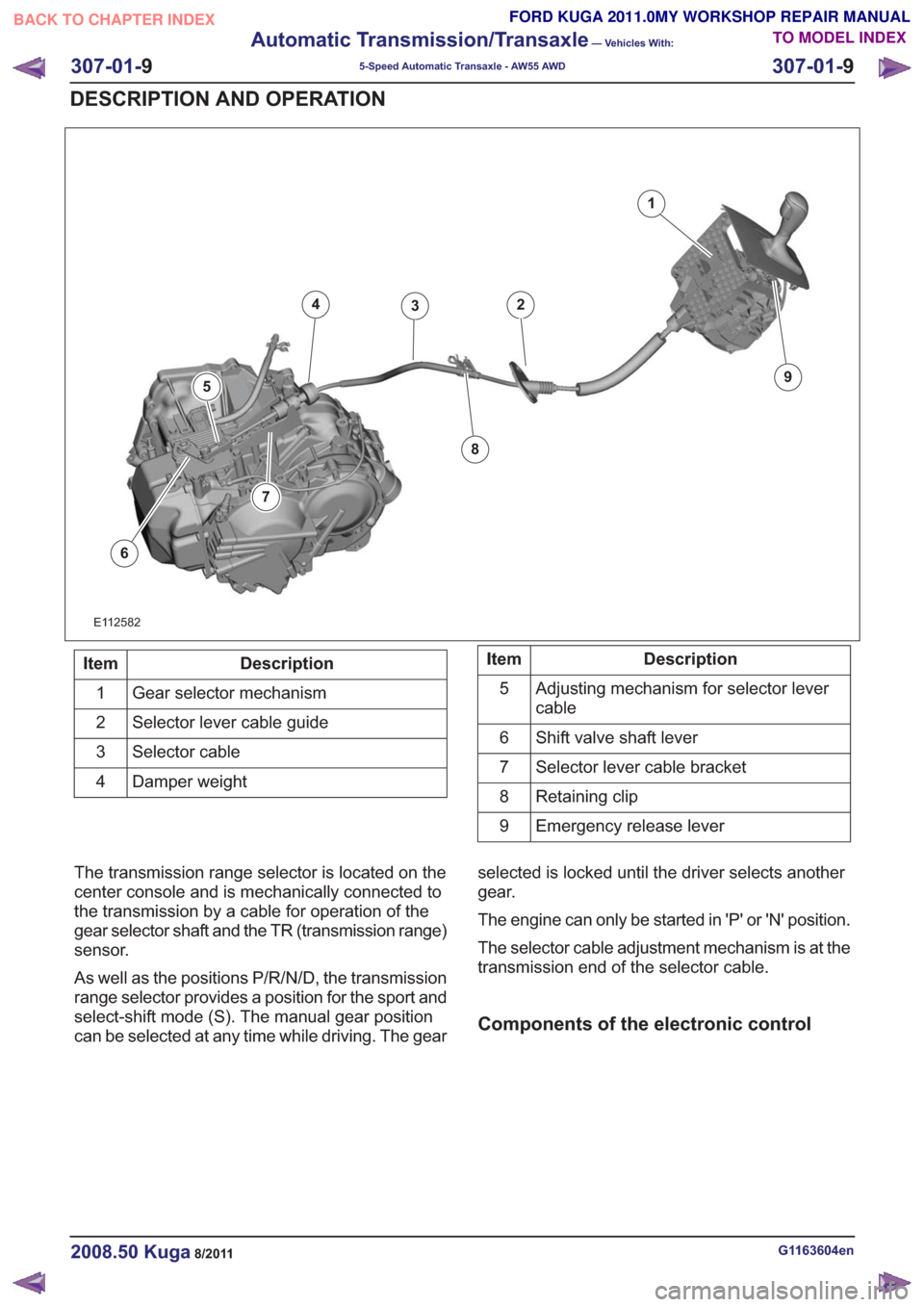
The transmission range selector is located on the
center console and is mechanically connected to
the transmission by a cable for operation of the
gear selector shaft and the TR (transmission range)
sensor.
As well as the positions P/R/N/D, the transmission
range selector provides a position for the sport and
select-shift mode (S). The manual gear position
can be selected at any time while driving. The gear selected is locked until the driver selects another
gear.
The engine can only be started in 'P' or 'N' position.
The selector cable adjustment mechanism is at the
transmission end of the selector cable.
Components of the electronic control
G1163604en2008.50 Kuga8/2011
307-01-
9
Automatic Transmission/Transaxle
— Vehicles With:
5-Speed Automatic Transaxle - AW55 AWD
307-01- 9
DESCRIPTION AND OPERATION
TO MODEL INDEX
BACK TO CHAPTER INDEX
FORD KUGA 2011.0MY WORKSHOP REPAIR MANUAL