2011 FORD KUGA traction control
[x] Cancel search: traction controlPage 49 of 2057

Solvent-based Adhesives/Sealers - See
Solvents
Follow manufacturers instructions.
Water-based Adhesives/Sealers
Those based on polymer emulsions and rubber
latexes may contain small amounts of volatile toxic
and harmful chemicals. Skin and eye contact
should be avoided and adequate ventilation
provided during use.
Hot Melt Adhesives
In the solid state, they are safe. In the molten state
they may cause burns and health hazards may
arise from the inhalation of toxic fumes.
Use appropriate protective clothing and a
thermostatically controlled heater with a thermal
cut-out and adequate extraction.
Resin-based Adhesives/Sealers, for
example Epoxide and Formaldehyde
Resin-based
Mixing should be carried out in well ventilated
areas, as harmful or toxic volatile chemicals may
be released.
Skin contact with uncured resins and hardeners
can result in irritation, dermatitis, and absorption
of toxic or harmful chemicals through the skin.
Splashes can damage the eyes.
Provide adequate ventilation and avoid skin and
eye contact.
Anaerobic, Cyanoacrylate (super-glues)
and other Acrylic Adhesives
Many are irritant, sensitizing or harmful to the skin
and respiratory tract. Some are eye irritants.
Skin and eye contact should be avoided and the
manufacturers instructions followed.
Cyanoacrylate adhesives (super-glues) MUST NOT
contact the skin or eyes. If skin or eye tissue is
bonded, cover with a clean moist pad and SEEK
IMMEDIATE MEDICAL ATTENTION. Do not
attempt to pull tissue apart. Use in well ventilated
areas as vapors can cause irritation to the nose
and eyes.For two-pack systems see Resin-based and
Isocyanate Adhesives/Sealers.
Isocyanate (Polyurethane)
Adhesives/Sealers
See also
Resin-based Adhesives.
Individuals suffering from asthma or respiratory
allergies should not work with or near these
materials as sensitivity reactions can occur.
Over exposure is irritating to the eyes and
respiratory system. Excessive concentrations may
produce effects on the nervous system including
drowsiness. In extreme cases, loss of
consciousness may result. Long term exposure to
vapor concentrations may result in adverse health
effects.
Prolonged contact with the skin may have a
defatting effect which may lead to skin irritation
and in some cases, dermatitis.
Splashes entering the eye will cause discomfort
and possible damage.
Any spraying should preferably be carried out in
exhaust ventilated booths, removing vapors and
spray droplets from the breathing zone.
Wear appropriate gloves, eye and respiratory
protection.
Antifreeze
See also Fire, Solvents.
For example isopropanol, ethylene glycol,
methanol.
Highly flammable, flammable, combustible.
Used in vehicle coolant systems, brake air pressure
systems, screenwash solutions.
For additional information, refer to: Engine Cooling
System Health and Safety Precautions (100-00
General Information, Description and Operation).
Asbestos
See also Warning Symbols on Vehicles at the end
of this subsection.
Breathing asbestos dust may cause lung damage
or, in some cases, cancer.
Used in brake and clutch linings, transmission
brake bands and gaskets.
G566527en2008.50 Kuga8/2011
100-00- 43
General Information
100-00- 43
DESCRIPTION AND OPERATION
TO MODEL INDEX
BACK TO CHAPTER INDEX
FORD KUGA 2011.0MY WORKSHOP REPAIR MANUAL
Page 183 of 2057

Instrument Cluster and Panel Illumination
Refer to
Wiring Diagrams Section 413-00, for
schematic and connector information.
Principles of Operation
NOTE: A new instrument cluster must be
configured.
The instrument cluster and panel illumination
consists of dimmable and non-dimmable
illumination. The dimmable panel illumination is
controlled by the panel illumination switch (part of
the headlamp switch), which allows the brightness
level of the backlights to be adjusted dependent
on the customer preference. When the headlamp
switch is in the parking lamps ON or headlamps
ON position, the intensity of the backlighting can
be adjusted using the panel dimmer switch. The
non dimmable illumination allows for full intensity
dependant on the ignition switch position.
Instrument Cluster and Dimmable
Backlighting A.
Tachometer
B. Engine coolant temperature gauge
C. Fuel gauge
D. Speedometer
E. Information display
The dimmable illumination utilizes light emitting
diodes (LEDs) and bulb(s). The following dimmable
components are backlight using LEDs only:
• ashtray
• cigar lighter
• transmission control lever
• heater control panel
• audio unit • navigation system display module
• instrument cluster
• climate control module
• hazard switch
• traction control system disable switch
• right-hand and left-hand heated front seat
switch(es)
Inspection and Verification
1. Verify the customer concern.
2. Visually inspect for obvious signs of mechanical
or electrical damage.
Visual Inspection Chart Electrical
Mechanical
– Fuse(s)
– Loose or corrodedconnector(s)
– Instrument cluster
– Wiring Harness
– Circuit
– LED(s)
– Bulb(s)
– Engine/engine
compartment or
underbody compon-
ents
– Fluid levels
– Accessory installa- tion
3. If an obvious cause for an observed or reported concern is found, correct the cause (if possible)
before proceeding to the next step.
4. If the cause is not visually evident, verify the symptom and refer to the diagnostic tab within
the Ford approved diagnostic tool. G1054961en
2008.50 Kuga 8/2011 413-00-2
Instrument Cluster and Panel Illumination
413-00-2
DIAGNOSIS AND TESTINGTO MODEL INDEX
BACK TO CHAPTER INDEX
FORD KUGA 2011.0MY WORKSHOP REPAIR MANUALE98738ABCED
Page 1251 of 2057
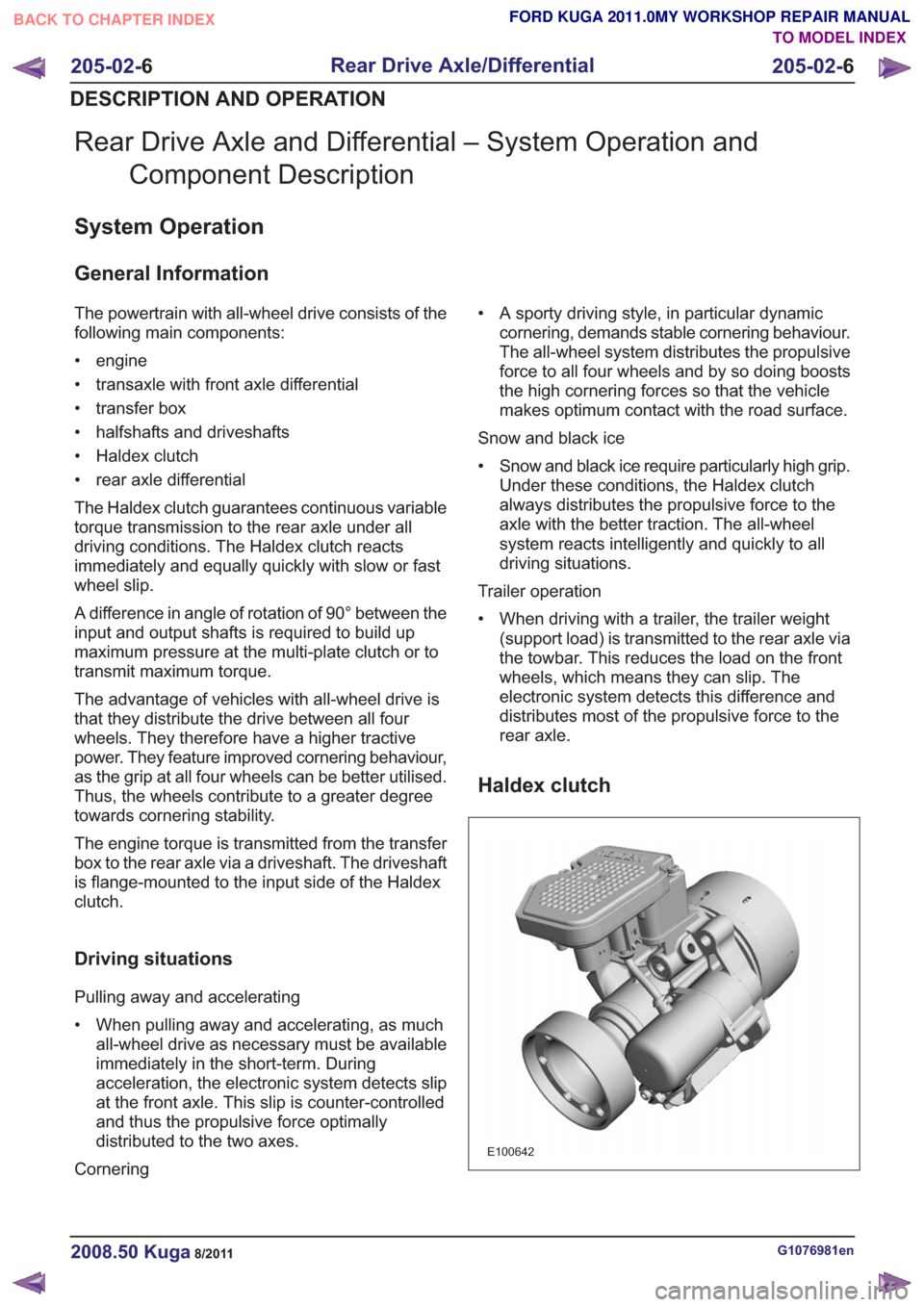
Rear Drive Axle and Differential – System Operation andComponent Description
System Operation
General Information
The powertrain with all-wheel drive consists of the
following main components:
• engine
• transaxle with front axle differential
• transfer box
• halfshafts and driveshafts
• Haldex clutch
• rear axle differential
The Haldex clutch guarantees continuous variable
torque transmission to the rear axle under all
driving conditions. The Haldex clutch reacts
immediately and equally quickly with slow or fast
wheel slip.
A difference in angle of rotation of 90° between the
input and output shafts is required to build up
maximum pressure at the multi-plate clutch or to
transmit maximum torque.
The advantage of vehicles with all-wheel drive is
that they distribute the drive between all four
wheels. They therefore have a higher tractive
power. They feature improved cornering behaviour,
as the grip at all four wheels can be better utilised.
Thus, the wheels contribute to a greater degree
towards cornering stability.
The engine torque is transmitted from the transfer
box to the rear axle via a driveshaft. The driveshaft
is flange-mounted to the input side of the Haldex
clutch.
Driving situations
Pulling away and accelerating
• When pulling away and accelerating, as muchall-wheel drive as necessary must be available
immediately in the short-term. During
acceleration, the electronic system detects slip
at the front axle. This slip is counter-controlled
and thus the propulsive force optimally
distributed to the two axes.
Cornering • A sporty driving style, in particular dynamic
cornering, demands stable cornering behaviour.
The all-wheel system distributes the propulsive
force to all four wheels and by so doing boosts
the high cornering forces so that the vehicle
makes optimum contact with the road surface.
Snow and black ice
• Snow and black ice require particularly high grip. Under these conditions, the Haldex clutch
always distributes the propulsive force to the
axle with the better traction. The all-wheel
system reacts intelligently and quickly to all
driving situations.
Trailer operation
• When driving with a trailer, the trailer weight (support load) is transmitted to the rear axle via
the towbar. This reduces the load on the front
wheels, which means they can slip. The
electronic system detects this difference and
distributes most of the propulsive force to the
rear axle.
Haldex clutch
E100642
G1076981en2008.50 Kuga8/2011
205-02- 6
Rear Drive Axle/Differential
205-02- 6
DESCRIPTION AND OPERATION
TO MODEL INDEX
BACK TO CHAPTER INDEX
FORD KUGA 2011.0MY WORKSHOP REPAIR MANUAL
Page 1252 of 2057
General overview
Haldex clutches of the 3rd and 4th generations are
used in the Ford Kuga.
The development of the third generation Haldex
clutch represents a big step forward in modern
all-wheel technology. The Haldex clutch is
electro-hydraulically controlled. Additional
information is taken into consideration during
control tasks via the all-wheel drive control unit.
Slip alone is no longer decisive for the distribution
of the propulsive forces; the vehicle's driving
dynamics are also taken into consideration. The
control unit accesses the driving-related data via
the data bus. With this data, the control unit has
all the essential information about speed, cornering,
coasting or traction operation, and can optimally
react to every driving situation.
Compared with the previous generation, the 4th
generation Haldex clutches operate with higher
pressure and achieve shorter response times when
distributing the drive forces.
Advantages of the Haldex clutch:
• Permanent all-wheel drive withelectronically-controlled multi-plate clutch
• Fast response
• No straining when parking and manoeuvring
• Compatible with different tyres (e.g. emergency spare wheel)
• Fully combinable with driving dynamic control systems
The driveshaft is connected to the input shaft of
the Haldex clutch. Within the Haldex clutch, the
input shaft is separated from the output shaft to
the rear axle differential by means of a multi-plate
clutch. Torque is only transmitted to the rear axle
differential when the plate assembly of the Haldex
clutch is closed.
The multi-plate clutch is electro-hydraulically
controlled via the all-wheel drive control unit. For
ecological driving, the torque to the rear axle is reduced to a minimum up to a throttle position of
approx. 50%. A prerequisite for this is that there is
no difference in speed in the Haldex clutch between
the input and output shafts.
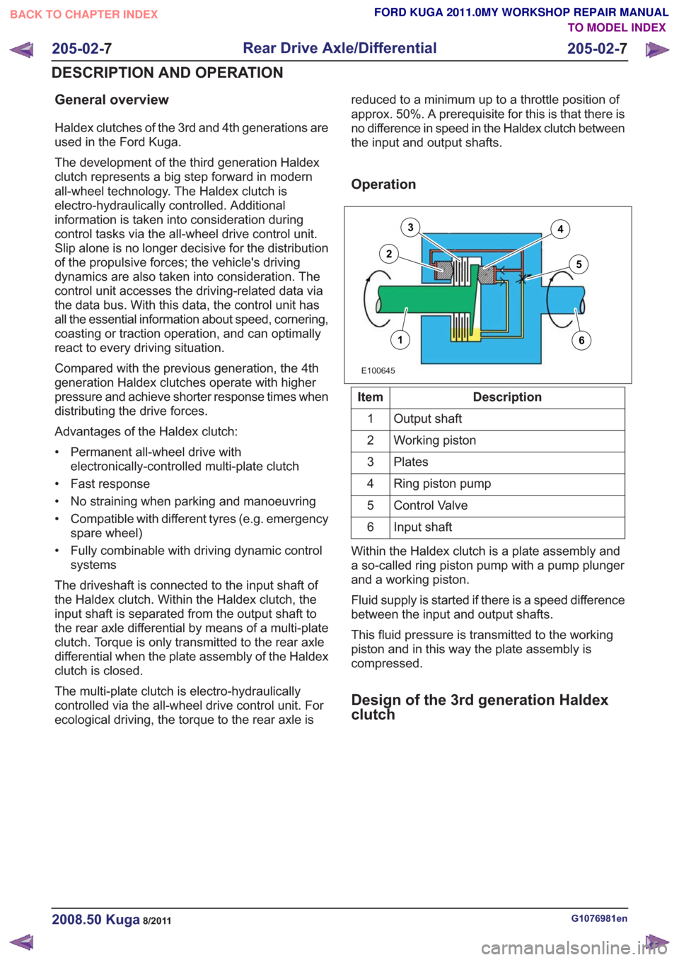
Operation
E100645
16
3
25
4
Description
Item
Output shaft
1
Working piston
2
Plates
3
Ring piston pump
4
Control Valve
5
Input shaft
6
Within the Haldex clutch is a plate assembly and
a so-called ring piston pump with a pump plunger
and a working piston.
Fluid supply is started if there is a speed difference
between the input and output shafts.
This fluid pressure is transmitted to the working
piston and in this way the plate assembly is
compressed.
Design of the 3rd generation Haldex
clutch
G1076981en2008.50 Kuga8/2011
205-02- 7
Rear Drive Axle/Differential
205-02- 7
DESCRIPTION AND OPERATION
TO MODEL INDEX
BACK TO CHAPTER INDEX
FORD KUGA 2011.0MY WORKSHOP REPAIR MANUAL
Page 1261 of 2057
6
7
8
9
10
11
1
2
3
4
5
6
7
8
9
10
11
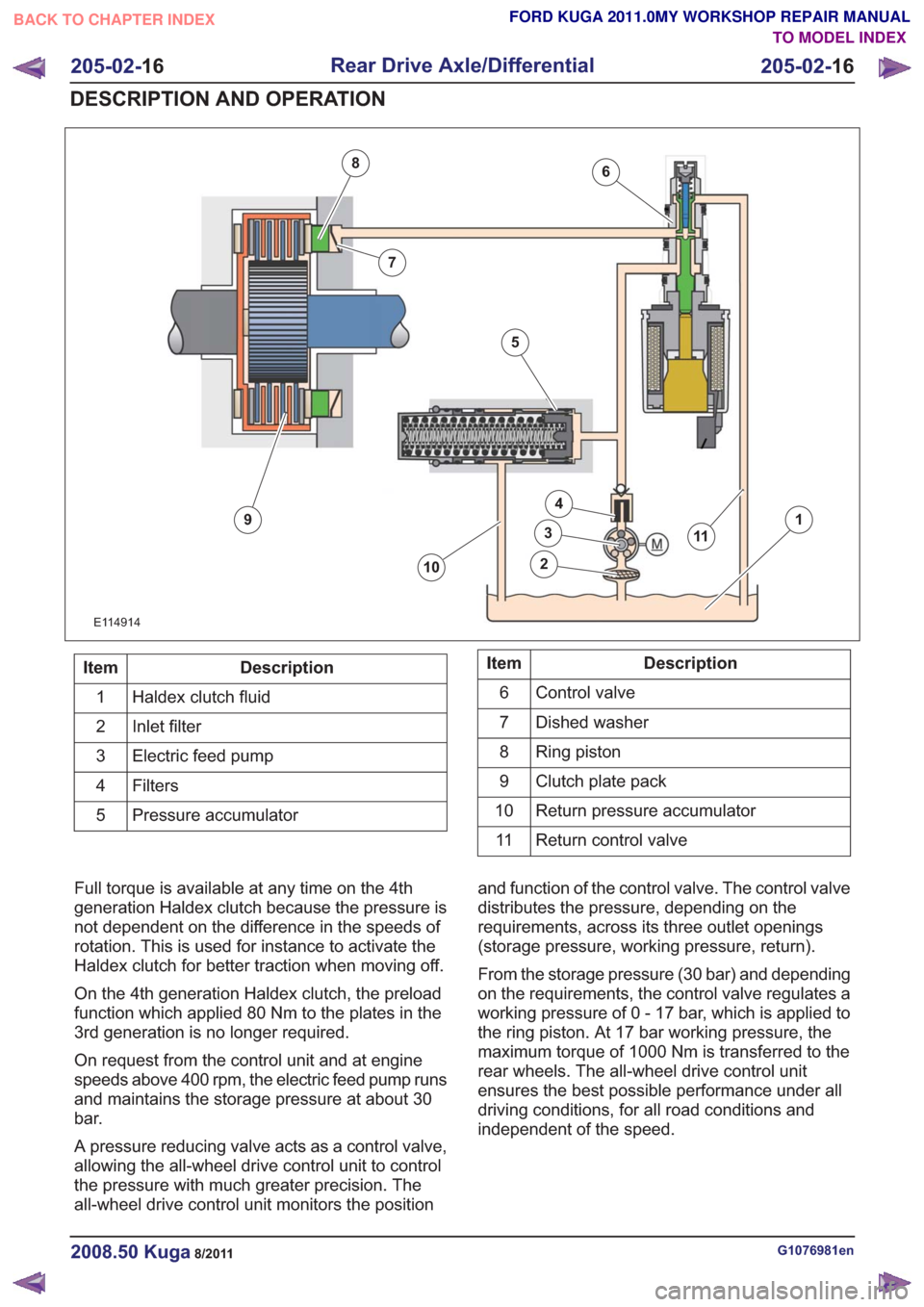
E114914
Description
Item
Haldex clutch fluid
1
Inlet filter
2
Electric feed pump
3
Filters4
Pressure accumulator
5Description
Item
Control valve
6
Dished washer
7
Ring piston
8
Clutch plate pack
9
Return pressure accumulator
10
Return control valve
11
Full torque is available at any time on the 4th
generation Haldex clutch because the pressure is
not dependent on the difference in the speeds of
rotation. This is used for instance to activate the
Haldex clutch for better traction when moving off.
On the 4th generation Haldex clutch, the preload
function which applied 80 Nm to the plates in the
3rd generation is no longer required.
On request from the control unit and at engine
speeds above 400 rpm, the electric feed pump runs
and maintains the storage pressure at about 30
bar.
A pressure reducing valve acts as a control valve,
allowing the all-wheel drive control unit to control
the pressure with much greater precision. The
all-wheel drive control unit monitors the position and function of the control valve. The control valve
distributes the pressure, depending on the
requirements, across its three outlet openings
(storage pressure, working pressure, return).
From the storage pressure (30 bar) and depending
on the requirements, the control valve regulates a
working pressure of 0 - 17 bar, which is applied to
the ring piston. At 17 bar working pressure, the
maximum torque of 1000 Nm is transferred to the
rear wheels. The all-wheel drive control unit
ensures the best possible performance under all
driving conditions, for all road conditions and
independent of the speed.
G1076981en2008.50 Kuga8/2011
205-02-
16
Rear Drive Axle/Differential
205-02- 16
DESCRIPTION AND OPERATION
TO MODEL INDEX
BACK TO CHAPTER INDEX
FORD KUGA 2011.0MY WORKSHOP REPAIR MANUAL
Page 1428 of 2057
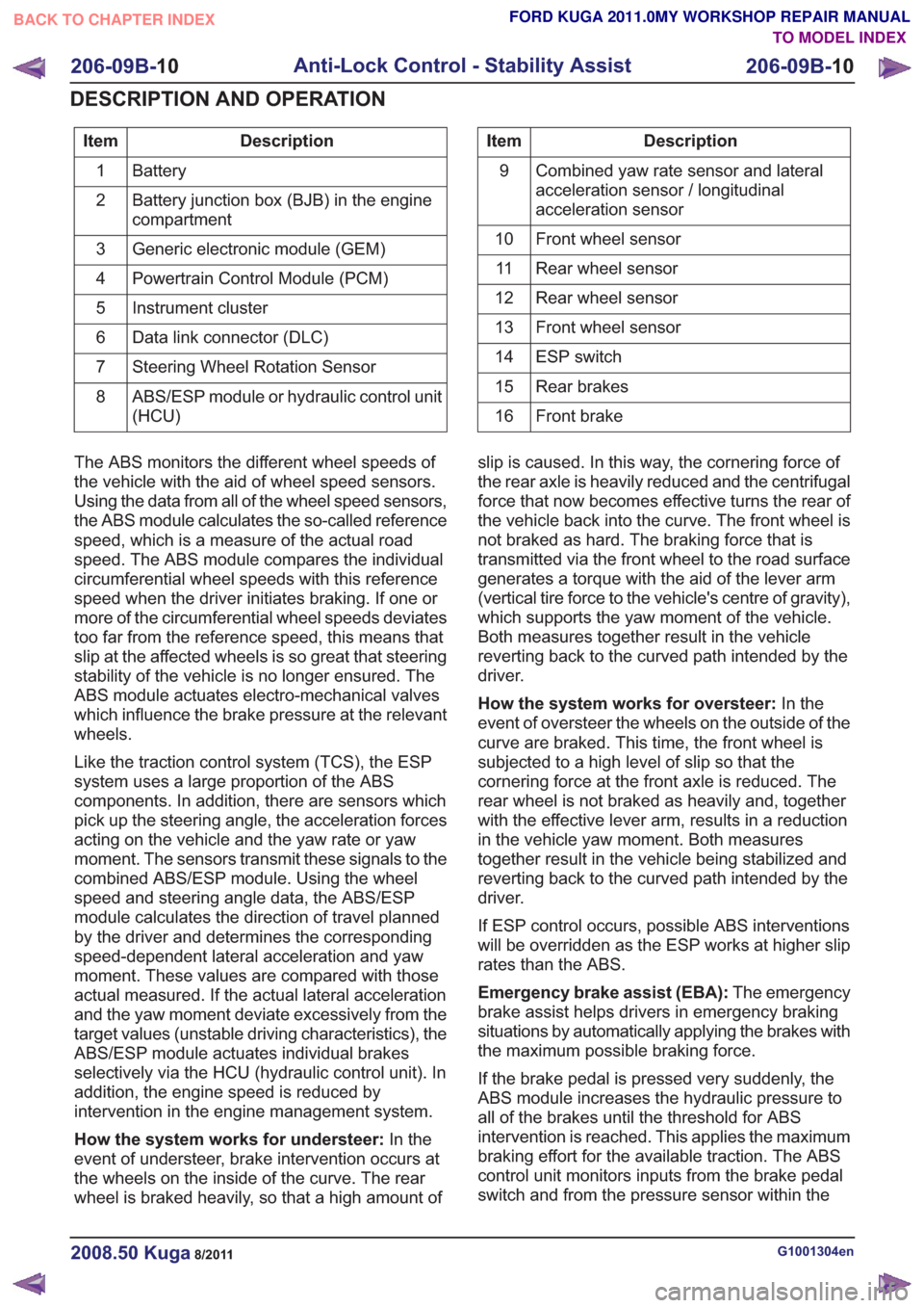
Description
Item
Battery
1
Battery junction box (BJB) in the engine
compartment
2
Generic electronic module (GEM)
3
Powertrain Control Module (PCM)
4
Instrument cluster
5
Data link connector (DLC)
6
Steering Wheel Rotation Sensor
7
ABS/ESP module or hydraulic control unit
(HCU)
8Description
Item
Combined yaw rate sensor and lateral
acceleration sensor / longitudinal
acceleration sensor
9
Front wheel sensor
10
Rear wheel sensor
11
Rear wheel sensor
12
Front wheel sensor
13
ESP switch
14
Rear brakes
15
Front brake
16
The ABS monitors the different wheel speeds of
the vehicle with the aid of wheel speed sensors.
Using the data from all of the wheel speed sensors,
the ABS module calculates the so-called reference
speed, which is a measure of the actual road
speed. The ABS module compares the individual
circumferential wheel speeds with this reference
speed when the driver initiates braking. If one or
more of the circumferential wheel speeds deviates
too far from the reference speed, this means that
slip at the affected wheels is so great that steering
stability of the vehicle is no longer ensured. The
ABS module actuates electro-mechanical valves
which influence the brake pressure at the relevant
wheels.
Like the traction control system (TCS), the ESP
system uses a large proportion of the ABS
components. In addition, there are sensors which
pick up the steering angle, the acceleration forces
acting on the vehicle and the yaw rate or yaw
moment. The sensors transmit these signals to the
combined ABS/ESP module. Using the wheel
speed and steering angle data, the ABS/ESP
module calculates the direction of travel planned
by the driver and determines the corresponding
speed-dependent lateral acceleration and yaw
moment. These values are compared with those
actual measured. If the actual lateral acceleration
and the yaw moment deviate excessively from the
target values (unstable driving characteristics), the
ABS/ESP module actuates individual brakes
selectively via the HCU (hydraulic control unit). In
addition, the engine speed is reduced by
intervention in the engine management system.
How the system works for understeer: In the
event of understeer, brake intervention occurs at
the wheels on the inside of the curve. The rear
wheel is braked heavily, so that a high amount of slip is caused. In this way, the cornering force of
the rear axle is heavily reduced and the centrifugal
force that now becomes effective turns the rear of
the vehicle back into the curve. The front wheel is
not braked as hard. The braking force that is
transmitted via the front wheel to the road surface
generates a torque with the aid of the lever arm
(vertical tire force to the vehicle's centre of gravity),
which supports the yaw moment of the vehicle.
Both measures together result in the vehicle
reverting back to the curved path intended by the
driver.
How the system works for oversteer:
In the
event of oversteer the wheels on the outside of the
curve are braked. This time, the front wheel is
subjected to a high level of slip so that the
cornering force at the front axle is reduced. The
rear wheel is not braked as heavily and, together
with the effective lever arm, results in a reduction
in the vehicle yaw moment. Both measures
together result in the vehicle being stabilized and
reverting back to the curved path intended by the
driver.
If ESP control occurs, possible ABS interventions
will be overridden as the ESP works at higher slip
rates than the ABS.
Emergency brake assist (EBA): The emergency
brake assist helps drivers in emergency braking
situations by automatically applying the brakes with
the maximum possible braking force.
If the brake pedal is pressed very suddenly, the
ABS module increases the hydraulic pressure to
all of the brakes until the threshold for ABS
intervention is reached. This applies the maximum
braking effort for the available traction. The ABS
control unit monitors inputs from the brake pedal
switch and from the pressure sensor within the
G1001304en2008.50 Kuga8/2011
206-09B- 10
Anti-Lock Control - Stability Assist
206-09B- 10
DESCRIPTION AND OPERATION
TO MODEL INDEX
BACK TO CHAPTER INDEX
FORD KUGA 2011.0MY WORKSHOP REPAIR MANUAL
Page 2008 of 2057
control saves the current speed as the target
speed.
Cruise control goes into STANDBY mode in the
following situations:
• Operation of the brake pedal
• Operation of the clutch pedal
• Operation of the parking brake
• If the driver operates the accelerator pedal andthe saved target speed is subsequently
exceeded for more than 5 minutes.
• Pressing any cruise control button for more than 2 minutes
• Intervention by the traction control or electronic stability program (for longer than 40 ms)
• Shifting of the gear selector lever to the "N" position (vehicles with automatic transmission
only)
• Minimum speed falls below 40 km/h.
• Occurrence of particular DTC (diagnostic trouble code)
• faulty signal from the backup lamp switch
Cruise control is switched off when the "OFF"
button is pressed.
If the accelerator pedal is pressed down, the
vehicle speed increases. As soon as the pedal is
released, the speed falls to the saved target value. The following components supply the signals
needed by the cruise control:
• The APP sensor.
– The APP sensor identifies the currentposition of the accelerator pedal and sends
a PWM (pulse width modulation) signal to
the PCM and an analog DC (direct current)
signal to the GEM.
– If one or both of the APP sensors fails, a fault is stored in the PCM fault memory and cruise
control cannot be activated.
• BPP switch – The BPP switch tells the PCM whether thevehicle is being braked. In its rest state the
switch is closed and sends an earth signal
to the GEM. This signal is sent via the CAN
to the PCM.
– The brake light switch is likewise connected to the GEM and is opened in the rest state.
When the vehicle is braked, the brake light
switch sends a signal to the GEM. This
compares the signals from the BPP switch
and the brake light switch. If a discrepancy
occurs, a fault is stored in the error memory
of the GEM. Cruise control cannot be
activated.
• CPP switch – The CPP switch sends a ground signal to theGEM as soon as the clutch is operated. This
signal is passed on by the GEM via the CAN
bus to the PCM. This then supplies the signal
to the cruise control.
– If the CPP switch is incorrectly installed or set, cruise control cannot be activated.
• Wheel speed sensors – The wheel speed sensors record the speedof all the wheels. The recorded speed values
are sent to the ABS module via a hard-wired
connection. The ABS module calculates a
vehicle speed signal (VS signal) from the
speed values and the wheel diameter. This
vehicle speed signal is transferred via the
CAN bus to the PCM and supplied to the
cruise control. If the vehicle speed signal is
faulty, cruise control cannot be activated.
G1044191en2008.50 Kuga8/2011
310-03- 5
Speed Control
310-03- 5
DESCRIPTION AND OPERATION
TO MODEL INDEX
BACK TO CHAPTER INDEX
FORD KUGA 2011.0MY WORKSHOP REPAIR MANUAL