Page 1696 of 2057

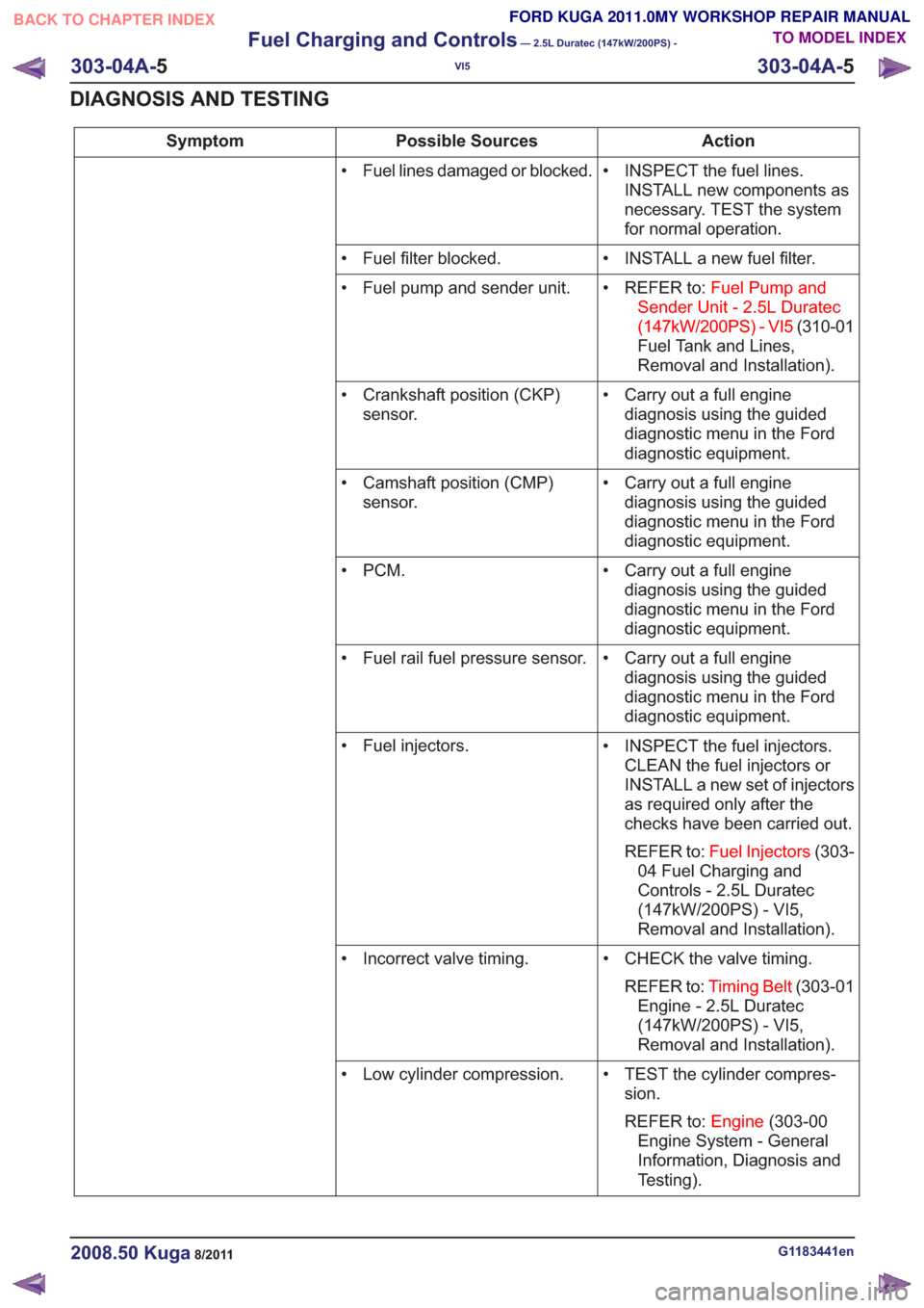
Action
Possible Sources
Symptom
• INSPECT the fuel lines.INSTALL new components as
necessary. TEST the system
for normal operation.
• Fuel lines damaged or blocked.
• INSTALL a new fuel filter.
• Fuel filter blocked.
• REFER to:Fuel Pump and
Sender Unit - 2.5L Duratec
(147kW/200PS) - VI5 (310-01
Fuel Tank and Lines,
Removal and Installation).
• Fuel pump and sender unit.
• Carry out a full enginediagnosis using the guided
diagnostic menu in the Ford
diagnostic equipment.
• Crankshaft position (CKP)
sensor.
• Carry out a full enginediagnosis using the guided
diagnostic menu in the Ford
diagnostic equipment.
• Camshaft position (CMP)
sensor.
• Carry out a full enginediagnosis using the guided
diagnostic menu in the Ford
diagnostic equipment.
•PCM.
• Carry out a full enginediagnosis using the guided
diagnostic menu in the Ford
diagnostic equipment.
• Fuel rail fuel pressure sensor.
• INSPECT the fuel injectors.CLEAN the fuel injectors or
INSTALL a new set of injectors
as required only after the
checks have been carried out.
REFER to: Fuel Injectors (303-
04 Fuel Charging and
Controls - 2.5L Duratec
(147kW/200PS) - VI5,
Removal and Installation).
• Fuel injectors.
• CHECK the valve timing.REFER to: Timing Belt (303-01
Engine - 2.5L Duratec
(147kW/200PS) - VI5,
Removal and Installation).
• Incorrect valve timing.
• TEST the cylinder compres-sion.
REFER to: Engine(303-00
Engine System - General
Information, Diagnosis and
Testing).
• Low cylinder compression.
G1183441en2008.50 Kuga8/2011
303-04A-
5
Fuel Charging and Controls
— 2.5L Duratec (147kW/200PS) -
VI5
303-04A- 5
DIAGNOSIS AND TESTING
TO MODEL INDEX
BACK TO CHAPTER INDEX
FORD KUGA 2011.0MY WORKSHOP REPAIR MANUAL
Page 1790 of 2057

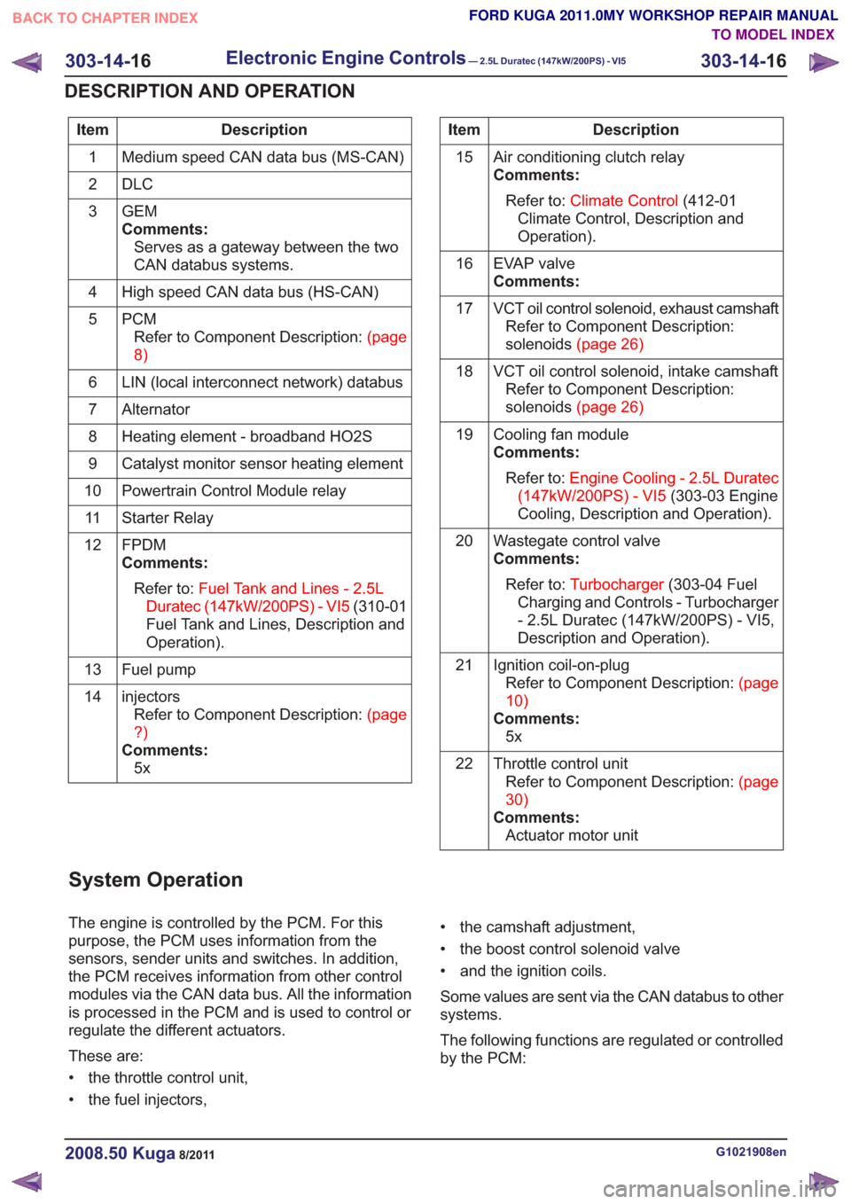
Description
Item
Medium speed CAN data bus (MS-CAN)
1
DLC
2
GEM
Comments:Serves as a gateway between the two
CAN databus systems.
3
High speed CAN data bus (HS-CAN)
4
PCMRefertoComponentDescription:(page
8)
5
LIN (local interconnect network) databus
6
Alternator
7
Heating element - broadband HO2S
8
Catalyst monitor sensor heating element
9
Powertrain Control Module relay
10
Starter Relay
11
FPDM
Comments:Refer to: Fuel Tank and Lines - 2.5L
Duratec (147kW/200PS) - VI5 (310-01
Fuel Tank and Lines, Description and
Operation).
12
Fuel pump
13
injectorsRefertoComponentDescription:(page
?)
Comments: 5x
14Description
Item
Air conditioning clutch relay
Comments:Refer to: Climate Control (412-01
Climate Control, Description and
Operation).
15
EVAP valve
Comments:
16
VCT oil control solenoid, exhaust camshaftRefer to Component Description:
solenoids(page26)
17
VCT oil control solenoid, intake camshaftRefer to Component Description:
solenoids(page26)
18
Cooling fan module
Comments:Refer to: Engine Cooling - 2.5L Duratec
(147kW/200PS) - VI5 (303-03 Engine
Cooling, Description and Operation).
19
Wastegate control valve
Comments:Refer to: Turbocharger (303-04 Fuel
Charging and Controls - Turbocharger
- 2.5L Duratec (147kW/200PS) - VI5,
Description and Operation).
20
Ignition coil-on-plugRefertoComponentDescription:(page
10)
Comments: 5x
21
Throttle control unitRefertoComponentDescription:(page
30)
Comments: Actuator motor unit
22
System Operation
The engine is controlled by the PCM. For this
purpose, the PCM uses information from the
sensors, sender units and switches. In addition,
the PCM receives information from other control
modules via the CAN data bus. All the information
is processed in the PCM and is used to control or
regulate the different actuators.
These are:
• the throttle control unit,
• the fuel injectors, • the camshaft adjustment,
• the boost control solenoid valve
• and the ignition coils.
Some values are sent via the CAN databus to other
systems.
The following functions are regulated or controlled
by the PCM:
G1021908en2008.50 Kuga8/2011
303-14-
16
Electronic Engine Controls— 2.5L Duratec (147kW/200PS) - VI5303-14-
16
DESCRIPTION AND OPERATION
TO MODEL INDEX
BACK TO CHAPTER INDEX
FORD KUGA 2011.0MY WORKSHOP REPAIR MANUAL
Page 1978 of 2057
Fuel System Pressure Release
Release
1.Refer to: Petrol and Petrol-Ethanol Fuel
Systems Health and Safety Precautions
(100-00 General Information, Description and
Operation).
2. Remove the fuel pump and sender unit fuse.
3. Start the engine and allow it to idle until the
engine stalls.
4. Crank the engine for approximately five seconds
to make sure that the fuel rail pressure is
released.
5. Install the fuel pump and sender unit fuse.
G551380en2008.50 Kuga8/2011
310-00- 10
Fuel System - General Information
310-00- 10
GENERAL PROCEDURES
TO MODEL INDEX
BACK TO CHAPTER INDEX
FORD KUGA 2011.0MY WORKSHOP REPAIR MANUAL
Page 1979 of 2057

Fuel Tank Draining
General EquipmentFluid Container
Fuel Tank Draining Equipment
Hose Clamp Remover/Installer
Activation
CAUTION: If the fuel tank has been filled
with the wrong type of fuel, the engine
must not be started.
NOTE: Removal steps in this procedure may
contain installation details.
6. Refer to: Petrol and Petrol-Ethanol Fuel
Systems Health and Safety Precautions
(100-00 General Information, Description and
Operation).
7. Refer to: Lifting(100-02 Jacking and Lifting,
Description and Operation).
8. WARNINGS:
Fuel may still be present in the fuel tank
after draining.
Be prepared to collect escaping fluids.
CAUTION: Use suitable paper to absorb
any escaping fluid. NOTE:
Make sure that a new component is
installed.
• General Equipment: Hose Clamp Remover/Installer
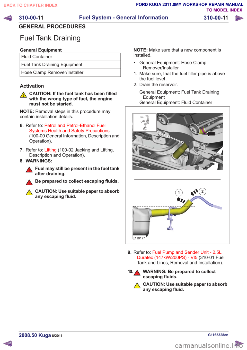
1. Make sure, that the fuel filler pipe is above the fuel level .
2. Drain the reservoir.
General Equipment: Fuel Tank DrainingEquipment
General Equipment: Fluid Container12
E116177
9. Refer to: Fuel Pump and Sender Unit - 2.5L
Duratec (147kW/200PS) - VI5 (310-01 Fuel
Tank and Lines, Removal and Installation).
10. WARNING: Be prepared to collect escaping fluids.
CAUTION: Use suitable paper to absorb
any escaping fluid.
G1165328en2008.50 Kuga8/2011
310-00- 11
Fuel System - General Information
310-00- 11
GENERAL PROCEDURES
TO MODEL INDEX
BACK TO CHAPTER INDEX
FORD KUGA 2011.0MY WORKSHOP REPAIR MANUAL
Page 1981 of 2057

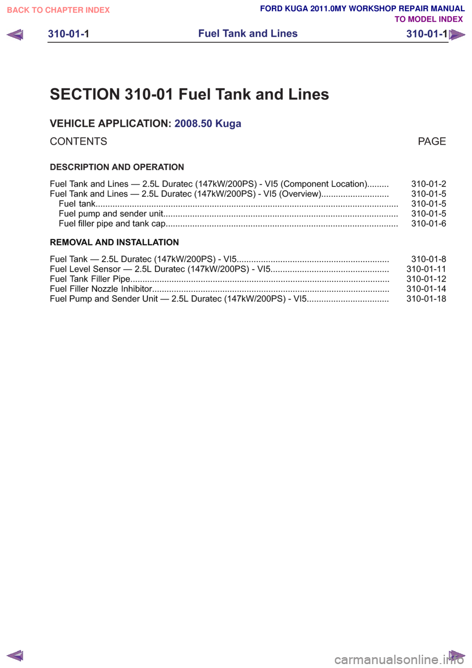
SECTION 310-01 Fuel Tank and Lines
VEHICLE APPLICATION:2008.50 Kuga
PA G E
CONTENTS
DESCRIPTION AND OPERATION
310-01-2
Fuel Tank and Lines — 2.5L Duratec (147kW/200PS) - VI5 (Component Location) .........
310-01-5
Fuel Tank and Lines — 2.5L Duratec (147kW/200PS) - VI5 (Overview) ............................
310-01-5
Fuel tank ........................................................................\
.....................................................
310-01-5
Fuel pump and sender unit ........................................................................\
.........................
310-01-6
Fuel filler pipe and tank cap........................................................................\
........................
REMOVAL AND INSTALLATION 310-01-8
Fuel Tank — 2.5L Duratec (147kW/200PS) - VI5 ...............................................................
310-01-11
Fuel Level Sensor — 2.5L Duratec (147kW/200PS) - VI5 .................................................
310-01-12
Fuel Tank Filler Pipe ........................................................................\
...................................
310-01-14
Fuel Filler Nozzle Inhibitor ........................................................................\
..........................
310-01-18
Fuel Pump and Sender Unit — 2.5L Duratec (147kW/200PS) - VI5 ..................................
310-01-1
Fuel Tank and Lines
310-01- 1
.
TO MODEL INDEX
BACK TO CHAPTER INDEX
FORD KUGA 2011.0MY WORKSHOP REPAIR MANUAL
Page 1985 of 2057
Fuel Tank and Lines — 2.5L Duratec (147kW/200PS) - VI5 –Overview
Fuel tank
The fuel tank is the same on vehicles with FWD
and AWD. The fuel tank is saddle-shaped to accommodate the drive shaft and the exhaust
system. Depending on the design, the volume of
the tank is 56 liters or 66 liters.
Fuel pump and sender unit
E106247
12
Description
Item
Fuel pump and level indicator module,
left-hand side
Comments:Inactive side without separate fuel pump
1
Fuel pump and level indicator module,
right-hand side
2
G1090887en2008.50 Kuga8/2011
310-01-
5
Fuel Tank and Lines
310-01- 5
DESCRIPTION AND OPERATION
TO MODEL INDEX
BACK TO CHAPTER INDEX
FORD KUGA 2011.0MY WORKSHOP REPAIR MANUAL
Page 1990 of 2057
14.
E104859
x2
15. WARNING: Be prepared to collectescaping fluids.
CAUTION: Use suitable paper to absorb
any escaping fluid.
x2x2
E113946
16.
E104642
x2
Vehicles with fuel fired booster heater
NOTE:This step is only necessary when installing
a new component.
17. WARNING: Be prepared to collect escaping fluids.
CAUTION: Use suitable paper to absorb
any escaping fluid.
Refer to: Quick Release Coupling (310-00 Fuel
System - General Information, General
Procedures).
E113927
All vehicles
NOTE: This step is only necessary when installing
a new component.
18. Refer to: Fuel Pump and Sender Unit - 2.5L
Duratec (147kW/200PS) - VI5 (310-01 Fuel
Tank and Lines, Removal and Installation).
Installation
1. To install, reverse the removal procedure.
G1175018en2008.50 Kuga8/2011
310-01- 10
Fuel Tank and Lines
310-01- 10
REMOVAL AND INSTALLATION
TO MODEL INDEX
BACK TO CHAPTER INDEX
FORD KUGA 2011.0MY WORKSHOP REPAIR MANUAL
Page 1991 of 2057
Fuel Level Sensor — 2.5L Duratec (147kW/200PS) - VI5
Removal
1.Refer to: Fuel Pump and Sender Unit - 2.5L
Duratec (147kW/200PS) - VI5 (310-01 Fuel
Tank and Lines, Removal and Installation).
Installation
1. To install, reverse the removal procedure.
G1000788en2008.50 Kuga8/2011
310-01- 11
Fuel Tank and Lines
310-01- 11
REMOVAL AND INSTALLATION
TO MODEL INDEX
BACK TO CHAPTER INDEX
FORD KUGA 2011.0MY WORKSHOP REPAIR MANUAL