Page 1173 of 2057
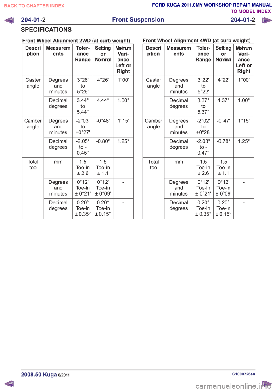
Front Wheel Alignment 2WD (at curb weight)
MaximumVari-
ance
Left or Right
Setting
or
Nominal
Toler-
ance
Range
Measurem
ents
Descri
ption
1°00'
4°26'
3°26'
to
5°26'
Degrees
and
minutes
Caster
angle
1.00°
4.44°
3.44°
to
5.44°
Decimal
degrees
1°15'
-0°48'
-2°03'
to
+0°27'
Degrees
and
minutes
Camber
angle
1.25°
-0.80°
-2.05°
to -
0.45°
Decimal
degrees
-1.5
Toe-in ±1.1
1.5
Toe-in ±2.6
mm
To t a l
toe
-
0°12'
Toe-in
± 0°09'
0°12'
Toe-in
± 0°21'
Degrees
and
minutes
-
0.20°
Toe-in
± 0.15°
0.20°
Toe-in
± 0.35°
Decimal
degrees Front Wheel Alignment 4WD (at curb weight)Maximum
Vari-
ance
Left or Right
Setting
or
Nominal
Toler-
ance
Range
Measurem
ents
Descri
ption
1°00'
4°22'
3°22'
to
5°22'
Degrees
and
minutes
Caster
angle
1.00°
4.37°
3.37°
to
5.37°
Decimal
degrees
1°15'
-0°47'
-2°02'
to
+0°28'
Degrees
and
minutes
Camber
angle
1.25°
-0.78°
-2.03°
to -
0.47°
Decimal
degrees
-1.5
Toe-in ±1.1
1.5
To e - i n ±2.6
mm
To t a l
toe
-
0°12'
Toe-in
± 0°09'
0°12'
To e - i n
±0°21'
Degrees
and
minutes
-
0.20°
Toe-in
± 0.15°
0.20°
To e - i n
±0.35°
Decimal
degrees
G1000726en2008.50 Kuga8/2011
204-01- 2
Front Suspension
204-01- 2
SPECIFICATIONS
TO MODEL INDEX
BACK TO CHAPTER INDEX
FORD KUGA 2011.0MY WORKSHOP REPAIR MANUAL
Page 1203 of 2057
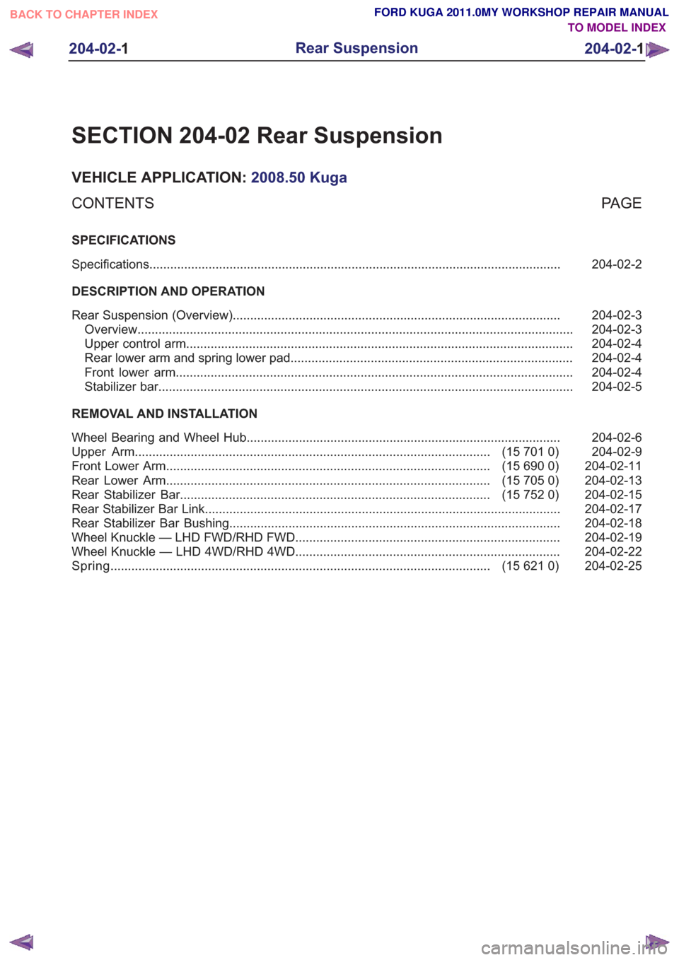
SECTION 204-02 Rear Suspension
VEHICLE APPLICATION:2008.50 Kuga
PA G E
CONTENTS
SPECIFICATIONS
204-02-2
Specifications ........................................................................\
..............................................
DESCRIPTION AND OPERATION 204-02-3
Rear Suspension (Overview) ........................................................................\
......................
204-02-3
Overview ........................................................................\
.....................................................
204-02-4
Upper control arm ........................................................................\
.......................................
204-02-4
Rear lower arm and spring lower pad ........................................................................\
.........
204-02-4
Front lower arm ........................................................................\
..........................................
204-02-5
Stabilizer bar ........................................................................\
...............................................
REMOVAL AND INSTALLATION 204-02-6
Wheel Bearing and Wheel Hub ........................................................................\
..................
204-02-9
(15 701 0)
Upper Arm ........................................................................\
..............................
204-02-11
(15 690 0)
Front Lower Arm ........................................................................\
.....................
204-02-13
(15 705 0)
Rear Lower Arm ........................................................................\
.....................
204-02-15
(15 752 0)
Rear Stabilizer Bar ........................................................................\
.................
204-02-17
Rear Stabilizer Bar Link ........................................................................\
..............................
204-02-18
Rear Stabilizer Bar Bushing ........................................................................\
.......................
204-02-19
Wheel Knuckle — LHD FWD/RHD FWD ........................................................................\
....
204-02-22
Wheel Knuckle — LHD 4WD/RHD 4WD ........................................................................\
....
204-02-25
(15 621 0)
Spring ........................................................................\
.....................................
204-02- 1
Rear Suspension
204-02- 1
.
TO MODEL INDEX
BACK TO CHAPTER INDEX
FORD KUGA 2011.0MY WORKSHOP REPAIR MANUAL
Page 1204 of 2057
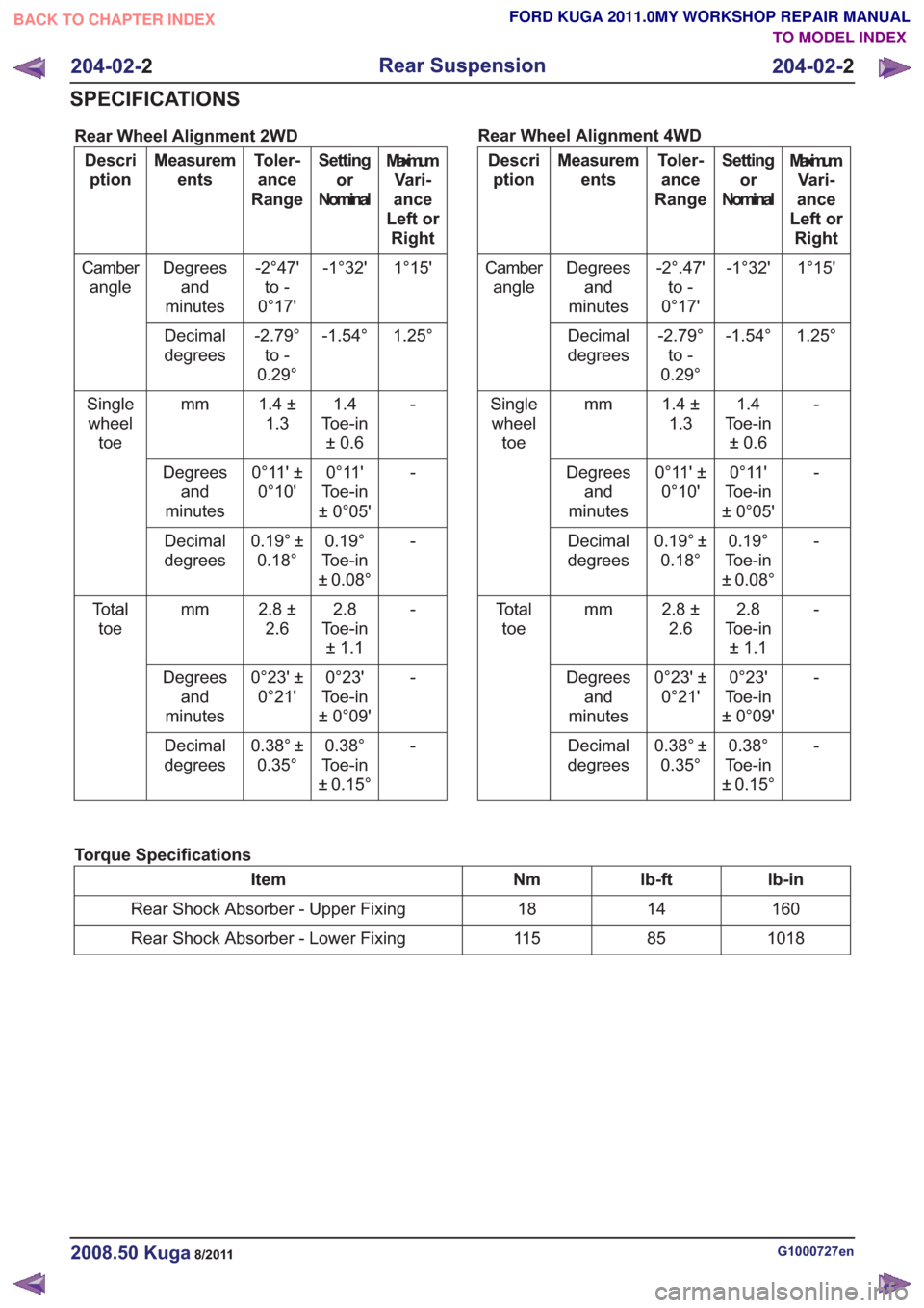
Rear Wheel Alignment 2WD
MaximumVari-
ance
Left or Right
Setting
or
Nominal
Toler-
ance
Range
Measurem
ents
Descri
ption
1°15'
-1°32'
-2°47'
to -
0°17'
Degrees
and
minutes
Camber
angle
1.25°
-1.54°
-2.79°
to -
0.29°
Decimal
degrees
-1.4
Toe-in ±0.6
1.4 ±
1.3
mm
Single
wheel toe
-
0°11'
Toe-in
± 0°05'
0°11' ±
0°10'
Degrees
and
minutes
-
0.19°
Toe-in
± 0.08°
0.19° ±
0.18°
Decimal
degrees
-2.8
Toe-in ±1.1
2.8 ±
2.6
mm
To t a l
toe
-
0°23'
Toe-in
± 0°09'
0°23' ±
0°21'
Degrees
and
minutes
-
0.38°
Toe-in
± 0.15°
0.38° ±
0.35°
Decimal
degrees Rear Wheel Alignment 4WDMaximum
Vari-
ance
Left or Right
Setting
or
Nominal
Toler-
ance
Range
Measurem
ents
Descri
ption
1°15'
-1°32'
-2°.47'
to -
0°17'
Degrees
and
minutes
Camber
angle
1.25°
-1.54°
-2.79°
to -
0.29°
Decimal
degrees
-1.4
Toe-in ±0.6
1.4 ±
1.3
mm
Single
wheel toe
-
0°11'
Toe-in
± 0°05'
0°11' ±
0°10'
Degrees
and
minutes
-
0.19°
Toe-in
± 0.08°
0.19° ±
0.18°
Decimal
degrees
-2.8
Toe-in ±1.1
2.8 ±
2.6
mm
To t a l
toe
-
0°23'
Toe-in
± 0°09'
0°23' ±
0°21'
Degrees
and
minutes
-
0.38°
Toe-in
± 0.15°
0.38° ±
0.35°
Decimal
degrees
Torque Specifications
lb-in
lb-ft
Nm
Item
160
14
18
Rear Shock Absorber - Upper Fixing
1018
85
11 5
Rear Shock Absorber - Lower Fixing
G1000727en2008.50 Kuga8/2011
204-02- 2
Rear Suspension
204-02- 2
SPECIFICATIONS
TO MODEL INDEX
BACK TO CHAPTER INDEX
FORD KUGA 2011.0MY WORKSHOP REPAIR MANUAL
Page 1224 of 2057
Wheel Knuckle — LHD 4WD/RHD 4WD
Removal
1.Refer to: Spring(204-02 Rear Suspension,
Removal and Installation).
2. Refer to: Wheel Bearing and Wheel Hub (204-02
Rear Suspension, Removal and Installation).
3.
E101643
4.
E99208
5.
E93214
6.
E93206
Installation
1. Fabricate a spacer.
E69209
226
40
2. Torque: 120Nm1.
2.NOTE: Only tighten the bolt finger tight at
this stage.
E932621
2
G1000760en2008.50 Kuga8/2011
204-02- 22
Rear Suspension
204-02- 22
REMOVAL AND INSTALLATION
TO MODEL INDEX
BACK TO CHAPTER INDEX
FORD KUGA 2011.0MY WORKSHOP REPAIR MANUAL
Page 1296 of 2057
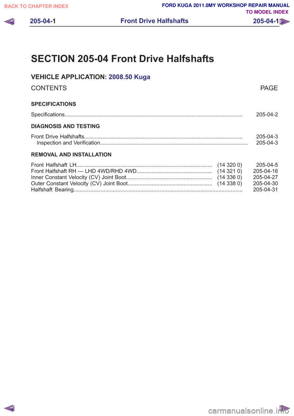
SECTION 205-04 Front Drive Halfshafts
VEHICLE APPLICATION:2008.50 Kuga
PA G E
CONTENTS
SPECIFICATIONS
205-04-2
Specifications ........................................................................\
..............................................
DIAGNOSIS AND TESTING 205-04-3
Front Drive Halfshafts ........................................................................\
.................................
205-04-3
Inspection and Verification ........................................................................\
..........................
REMOVAL AND INSTALLATION 205-04-5
(14 320 0)
Front Halfshaft LH ........................................................................\
..................
205-04-16
(14 321 0)
Front Halfshaft RH — LHD 4WD/RHD 4WD ..................................................
205-04-27
(14 336 0)
Inner Constant Velocity (CV) Joint Boot .........................................................
205-04-30
(14 338 0)
Outer Constant Velocity (CV) Joint Boot ........................................................
205-04-31
Halfshaft Bearing ........................................................................\
........................................
205-04-1
Front Drive Halfshafts
205-04- 1
.
TO MODEL INDEX
BACK TO CHAPTER INDEX
FORD KUGA 2011.0MY WORKSHOP REPAIR MANUAL
Page 1297 of 2057
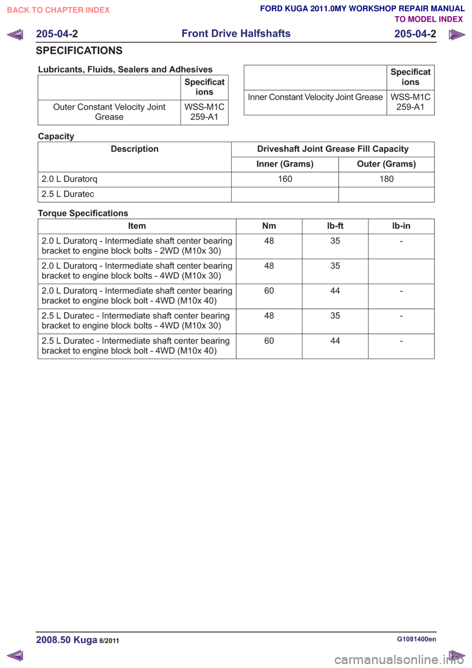
Lubricants, Fluids, Sealers and Adhesives
Specifications
WSS-M1C 259-A1
Outer Constant Velocity Joint
Grease
Specifications
WSS-M1C 259-A1
Inner Constant Velocity Joint Grease
Capacity
Driveshaft Joint Grease Fill Capacity
Description
Outer (Grams)
Inner (Grams)
180
160
2.0 L Duratorq
2.5 L Duratec
Torque Specifications
lb-in
lb-ft
Nm
Item
-
35
48
2.0 L Duratorq - Intermediate shaft center bearing
bracket to engine block bolts - 2WD (M10x 30)
35
48
2.0 L Duratorq - Intermediate shaft center bearing
bracket to engine block bolts - 4WD (M10x 30)
-
44
60
2.0 L Duratorq - Intermediate shaft center bearing
bracket to engine block bolt - 4WD (M10x 40)
-
35
48
2.5 L Duratec - Intermediate shaft center bearing
bracket to engine block bolts - 4WD (M10x 30)
-
44
60
2.5 L Duratec - Intermediate shaft center bearing
bracket to engine block bolt - 4WD (M10x 40)
G1081400en2008.50 Kuga8/2011
205-04- 2
Front Drive Halfshafts
205-04- 2
SPECIFICATIONS
TO MODEL INDEX
BACK TO CHAPTER INDEX
FORD KUGA 2011.0MY WORKSHOP REPAIR MANUAL
Page 1311 of 2057
Front Halfshaft RH — LHD 4WD/RHD 4WD(14 321 0)
Special Tool(s) / General Equipment204-159
Lever, Wheel Knuckle
14039
204-602
Installer, Halfshaft
E62067
204-605
Separator, Lower Arm Ball
Joint
E63772
204-609
Protection Cap, Ball Joint
Gaiter
E75372
205-071-01
Adapter for 205-071 (Thrust
Pad)
15026A01
211-020
Separator, Ball Joint
13006
Puller
Removal
1. NOTE:This step is only necessary when
installing a new component.
E99184
2. Refer to: Lifting(100-02 Jacking and Lifting,
Description and Operation).
Refer to: Wheel and Tire (204-04 Wheels and
Tires, Removal and Installation).
3. NOTE: This step is only necessary when
installing a new component.
E102112
G1076962en2008.50 Kuga8/2011
205-04- 16
Front Drive Halfshafts
205-04- 16
REMOVAL AND INSTALLATION
TO MODEL INDEX
BACK TO CHAPTER INDEX
FORD KUGA 2011.0MY WORKSHOP REPAIR MANUAL
Page 1322 of 2057
Inner Constant Velocity (CV) Joint Boot(14 336 0)
Special Tool(s) / General Equipment204-169
Clamping Tool, Boot
Retaining Clamp
14044
308-046
Installer, Transmission
Extension Housing
Bushing/Seal
16016
Flat-bladed screwdriver
Puller
Materials
Specification
Name
WSS-M1C259-A1 /
3M5J-M1C259-AA
Grease FD-R
Removal
1.
Remove the halfshaft.
Refer to: Front Halfshaft LH (205-04 Front Drive
Halfshafts, Removal and Installation).
Refer to: Front Halfshaft RH - LHD 4WD/RHD
4WD (205-04 Front Drive Halfshafts, Removal
and Installation). 2.
Discard the grease.
E105704
3.
E78743
4.General Equipment: Puller
E78744
G1076988en2008.50 Kuga8/2011
205-04- 27
Front Drive Halfshafts
205-04- 27
REMOVAL AND INSTALLATION
TO MODEL INDEX
BACK TO CHAPTER INDEX
FORD KUGA 2011.0MY WORKSHOP REPAIR MANUAL