2011 FORD KUGA CAB BUS
[x] Cancel search: CAB BUSPage 52 of 2057

dermatitis or be absorbed through the skin in
toxic or harmful quantities.
– Do not use emptied containers for other materials except when they have been cleaned
under supervised conditions.
– Do not sniff or smell chemical materials. Brief exposure to high concentrations of fumes can
be toxic or harmful.
Chlorofluorocarbons (CFC)
There is concern in the scientific community that
CFCs and Halons are depleting the upper ozone
layer which filters out harmful ultraviolet radiation.
Decreased filtration of ultraviolet radiation may
result in increases in skin cancer, cataracts and
immune system suppression in humans, as well
as decreased productivity of crops and aquatic
systems.
CFCs are used primarily as refrigerants in vehicle
air conditioning systems and as aerosol
propellants. Halons are used as fire extinguishants.
Clutch Fluids
See Brake fluids.
Clutch Linings and Pads
SeeAsbestos.
Corrosion Protection Materials
See also Solvents, Fire.
Highly flammable, flammable – observe No
Smoking policy.
These materials are varied and the manufacturers
instructions must be followed. They may contain
solvents, resins or petroleum products. Skin and
eye contact should be avoided. They should only
be sprayed in conditions of adequate ventilation
and not in confined spaces.
Cutting
See Welding.
Dewaxing
SeeSolvents andFuels (Kerosene).
Dusts
Powder, dusts or clouds may be irritant, harmful
or toxic. Avoid breathing dusts from powdery
chemical materials or those arising from dry
abrasion operations. Wear respiratory protection
if ventilation is inadequate.
Fine dusts of combustible material can present an
explosion hazard. Avoid explosive limits and
sources of ignition.
Electric Shock
Electric shock can result from the use of faulty
electrical equipment or from the misuse of
equipment in good condition.
Make sure that electrical equipment is maintained
in good condition and frequently tested. Faulty
equipment should be labeled and preferably
removed from the workstation.
Make sure that flexes, cables, plugs and sockets
are not frayed, kinked, cut, cracked or otherwise
damaged.
Make sure that electrical equipment and flexes do
not come into contact with water.
Make sure that electrical equipment is protected
by the correct rated fuse.
Never misuse electrical equipment and never use
equipment that is in any way faulty. The results
could be fatal.
Make sure that the cables of mobile electrical
equipment cannot get trapped and damaged, such
as in a vehicle hoist.
Make sure that the designated electrical workers
are trained in basic First Aid.
In cases of electrocution:
– switch off the power supply before approaching
the victim.
– if this is not possible push or drag the victim from the source of electricity using dry
non-conductive material.
– commence resuscitation if trained to do so.
– SUMMON MEDICAL ASSISTANCE.
Engine Oils
See Lubricants and Grease.
G566527en2008.50 Kuga8/2011
100-00- 45
General Information
100-00- 45
DESCRIPTION AND OPERATION
TO MODEL INDEX
BACK TO CHAPTER INDEX
FORD KUGA 2011.0MY WORKSHOP REPAIR MANUAL
Page 94 of 2057

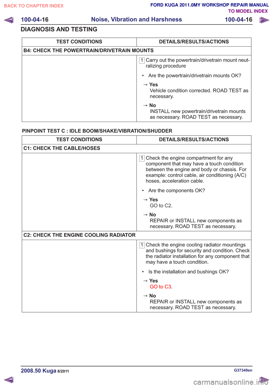
DETAILS/RESULTS/ACTIONS
TEST CONDITIONS
B4: CHECK THE POWERTRAIN/DRIVETRAIN MOUNTS
1 Carry out the powertrain/drivetrain mount neut-
ralizing procedure
• Are the powertrain/drivetrain mounts OK?
zYe s Vehicle condition corrected. ROAD TEST as
necessary.
zNoINSTALL new powertrain/drivetrain mounts
as necessary. ROAD TEST as necessary.
PINPOINT TEST C : IDLE BOOM/SHAKE/VIBRATION/SHUDDER
DETAILS/RESULTS/ACTIONS
TEST CONDITIONS
C1: CHECK THE CABLE/HOSES
1 Check the engine compartment for any
component that may have a touch condition
between the engine and body or chassis. For
example: control cable, air conditioning (A/C)
hoses, acceleration cable.
• Are the components OK?
zYe s GO to C2 .
zNo
REPAIR or INSTALL new components as
necessary. ROAD TEST as necessary.
C2: CHECK THE ENGINE COOLING RADIATOR
1 Check the engine cooling radiator mountings
and bushings for security and condition. Check
the radiator installation for any component that
may have a touch condition.
• Is the installation and bushings OK?
zYe s GO to C3 .
zNo
REPAIR or INSTALL new components as
necessary. ROAD TEST as necessary.
G37349en2008.50 Kuga8/2011
100-04- 16
Noise, Vibration and Harshness
100-04- 16
DIAGNOSIS AND TESTING
TO MODEL INDEX
BACK TO CHAPTER INDEX
FORD KUGA 2011.0MY WORKSHOP REPAIR MANUAL
Page 165 of 2057

System Operation
Electric Booster Heater
In diesel vehicles which give off little residual heat,
a booster heater is used to heat the passenger
compartment rapidly in the case of low ambient
temperatures.
If the interior temperature has been set to HI, or if
the heater controls have been switched to the
highest setting, the two-zone air conditioning
system sends an "electric booster heater ON"
request signal to the CAN (controller area network)
via the medium speed GEM bus. If a manual air
conditioning system is installed, the signal is
transmitted via a conventional cable connection.
The GEM switches on the electric booster heater
depending on the following parameters:
• Engine coolant temperature is below 60 °C.
• Ambient air temperature is below 10 °C.
• Sufficient generator capacity is available.
The electric booster heater electronics activate
three output stages as a function of a pulse width
modulated signal PWM (pulse width modulation)
generated by the GEM. The output stages switch
the three heating elements of the electric booster
heater ON or OFF individually, whereby the heating
periods of the individual elements can overlap. Due
to the variable switch-on duration, continuously
variable temperature control is possible. The overall
heating power of the three heating elements is
linearly proportional to the PWM signal. If the PWM
signal is below 10% or above 95%, the electric
booster heater is not activated.
The electric booster heater is switched off when
an engine coolant temperature of 70°C or an
ambient air temperature of 20°C is exceeded.
Fuel-fired heater - function diagram G1066982en
2008.50 Kuga 8/2011 412-02-12
Auxiliary Climate Control
412-02-12
DESCRIPTION AND OPERATIONTO MODEL INDEX
BACK TO CHAPTER INDEX
FORD KUGA 2011.0MY WORKSHOP REPAIR MANUAL12345671205304254481201056820108V58911121112E977670
Page 215 of 2057

Front parking aid speaker
The front parking aid speaker, in addition to its
actual function, is also used for audible indication
of various types of error in the front and rear
parking aids when the rear parking aid speaker
fails.
Parking aid switch
The parking aid switch is a non-locking switch with
an integrated LED for switching the parking aid on
and off. When pressed, the parking aid switch
momentarily connects a ground to the parking aid
module. The LED indicates when the parking aid
is active. The LED is controlled by the parking aid
module.
The parking aid switch allows the driver to disable
the parking aid when reverse gear is selected or
to activate the parking aid sensors when not in
reverse gear.
If a high tone is emitted for 3 seconds and the lights
in the switch flash, this indicates that there is a
fault. The system is then deactivated. Parking aid camera module
The data from the optional parking aid is sent to
the module via the Mid Speed CAN data bus. The
signals from the steering angle sensor are sent to
the module via cable. The module is connected to
the navigation device via a video-in/out cable.
Parking Aid Camera
The wide angle lens camera is fixed in the handle
strip of the tailgate. It is connected to the parking
aid camera module via a separate line.
G1034399en
2008.50 Kuga 8/2011 413-13-16
Parking Aid
413-13-16
DESCRIPTION AND OPERATIONTO MODEL INDEX
BACK TO CHAPTER INDEX
FORD KUGA 2011.0MY WORKSHOP REPAIR MANUALE89773 E97703 E97856 E97857
Page 384 of 2057

must use the same language. This language is
called a protocol.
At present, Ford uses three different data bus
systems. Depending upon model and equipment
level, all three data bus systems are used. Each
of these data bus systems has its own protocol.
Data bus systems
ISO 9141 bus
The International Organisation for Standardisation
ISO 9141 bus. This consists of a single wire and
is used exclusively for communication between the
modules and the Ford diagnostic unit. The fault
memories of the various modules are read out via
the ISO 9141 bus.
Local Interconnect Network (LIN) bus
The LIN bus is a standard specifically designed for
cost-effective communication between intelligent
sensors and actuators in vehicles. The LIN control
unit subnet is used in every situation where the
bandwidth and versatility of CAN is not needed.
The LIN specification comprises the LIN protocol,
a standard format for describing a complete LIN
and the interface between an LIN and the
application. An LIN comprises a LIN master and
one or more LIN slaves. The LIN utilizes the
master/slave principle for the purpose of bus
access control. This has the significant advantage
that few resources (CPU performance, ROM, RAM)
are required for bus management in the slave
module. The master is implemented in a control
module or a gateway which has the necessary
resources. All communication is initiated by the
master. Consequently, a message always consists
of a header, which is generated by the master, and
a response from the slave. The data transfer rate
is in the region of up to 20 Kbit/s. The LIN master
knows the time sequence of all data which are to
be transmitted. These data are transmitted by the
corresponding LIN slaves (e.g. ultrasonic sensors)
if they are requested to do so by the LIN master.
LIN is a single-wire bus, i.e. the data are
transmitted in the cable via one wire. Usually the
same cable is also used to provide the supply
voltage. The ground connection of the supply
voltage also acts as the ground connection of the
data transmission. An LIN does not use a
terminating resistor.
Controller Area Network (CAN) bus
This consists of two twisted wires and operates
serially (data is transmitted sequentially). It is used
for communication between the modules
themselves and between the modules and the Ford
diagnostic unit. The modules are connected to the
data bus in parallel. New modules can be
incorporated easily, without modifying the other
wiring or modules. The transmitted data is received
by every module connected to the control unit
network (CAN). As each data packet has an
identifier (label), in which the priority of the
message is determined as well as the content
identification, each module can detect whether or
not the data is relevant for its own information
processing. This enables several modules to be
addressed with a particular data packet and
supplied with data simultaneously. For this
purpose, it is ensured that important data (for
example from the ABS) is transmitted first. The
other modules are only able to submit their data to
the data bus after the high-priority messages have
been received.
The advantages of the CAN bus are:
• Minimization of wiring requirements
•
High degree of error protection (fault / fail-proof)
• Robustness
• Good extendibility
• Prioritization of messages
• Inexpensive
• Automatic repetition of faulty messages
• Independent system monitoring and the ability to disconnect faulty modules from the data bus
automatically
Due to the increased number of modules and the
resulting continued increase in data transfer, two
different CAN bus systems are used. Essentially,
they only differ in terms of their data transmission
rates and application areas.
To be able to distinguish between the individual
CAN bus systems, the CAN bus system with the
high transfer speed is called the high speed CAN
bus (HS-CAN). The data are transmitted at a baud
rate of 500 kB/s.
The CAN bus system with the medium transfer
speed is called the medium speed CAN bus
(MS-CAN) and is mainly used for communication
in the comfort electronics or the multimedia system.
The data are transmitted at a baud rate of 125 kB/s.
An interface (gateway) is used to exchange data
between the HS-CAN and the MS-CAN. This
provides the connection between the three CAN
databus systems and is installed in the GEM and
in the electronic instrument cluster. The number of
modules which are connected to the three databus G1030779en
2008.50 Kuga 8/2011 418-00-7
Module Communications Network
418-00-7
DESCRIPTION AND OPERATIONTO MODEL INDEX
BACK TO CHAPTER INDEX
FORD KUGA 2011.0MY WORKSHOP REPAIR MANUAL
Page 459 of 2057

• 4 minutes have elapsed since the button for the
heated windshield was pressed.
• The ignition switch is turned to the "I" or "0" position.
• The "Defrost" function is deactivated or the switch for the heated windscreen is pressed
again while the heated windscreen is still
switched on.
• The charging system warning indicator is switched on.
• The battery voltage falls below the threshold value for low battery voltage for more than 20
seconds (power management strategy). Manual
requests for switching on the heated windshield
by pressing the switch are ignored at this time.
• More than 4 minutes have passed since starting
the engine.
Heated rear window and heated external
mirrors
The GEM transmits a request signal via the CAN
bus to the door modules to switch on the heated
exterior mirrors.
The heated rear window and the heated exterior
mirrors are switched on by the GEM under the
following conditions:
• The switch for the heated rear window is pressed and the ignition switch is in the "II"
position.
• The "defrost" function of the air conditioning is activated and the ignition switch is in the position
"II".
• The battery voltage has exceeded 16 V for more
than 20 seconds (power management strategy).
Manual requests to switch off the heated rear
window by pressing the button are ignored at
this time.
• The engine was started at an outside air temperature below 4°C and an engine
temperature below 65°. Manual requests for
switching off the heated rear window by pressing
the switch are accepted.
NOTE: If the battery voltage returns to the normal
range then the disabling of the heated rear window
is cancelled - the heated rear window is then in a
switched-off state.
The GEM transmits a request signal via the CAN
bus to the door modules to switch off the heated
exterior mirrors. The heated rear window and the heated exterior
mirrors are switched off by the GEM under the
following conditions
• 14 minutes have elapsed since the button for
the heated rear window was pressed.
• The ignition switch is turned to the position "0", "I" or "III".
• The switch for the heated rear window is pressed or the "defrost" function of the air
conditioning is deactivated while the heated rear
window is switched on.
• The battery voltage has dropped below 10.3 V for more than 20 seconds (power management
strategy). Manual requests for switching on the
heated rear window by pressing the switch are
ignored at this time.
• More than 14 minutes have passed since starting the engine.
Ambient air temperature
The ambient air temperature sensor is connected
via a cable to the GEM. It measures the outside
air temperature to an accuracy of around ±0.5 °C.
The GEM broadcasts the ambient air temperature
on the medium speed CAN bus, where it can be
evaluated by various systems.
Brake fluid level
The brake fluid level switch is connected via a
cable to the GEM.
The GEM transmits a message on the medium
speed CAN bus. The instrument cluster then
transfers this message to the high speed CAN bus
where it is made available for various other
functions.
Automatic headlamps
Refer to: Exterior Lighting (417-01 Exterior Lighting,
Description and Operation).
Combined rain sensor/light sensor
Refer to: Exterior Lighting (417-01 Exterior Lighting,
Description and Operation). G1030788en
2008.50 Kuga 8/2011 419-10-9
Multifunction Electronic Modules
419-10-9
DESCRIPTION AND OPERATIONTO MODEL INDEX
BACK TO CHAPTER INDEX
FORD KUGA 2011.0MY WORKSHOP REPAIR MANUAL
Page 1433 of 2057

generate a square wave output signal. The signal
acts in proportion to the rotational speed of the
sensor ring. The ABS sensor rings are built into
the seals in the front wheel bearings. The ABS
module evaluates the signals from all four sensors
to calculate a vehicle speed signal based on the
rotational speeds of all wheels. The road speed is
transmitted on the CAN bus. The powertrain controlmodule (PCM) uses this signal and the
programmed tire size to calculate the vehicle
speed. The calculated vehicle speed is forwarded
on the CAN bus and is requested by other control
units that need this input information.
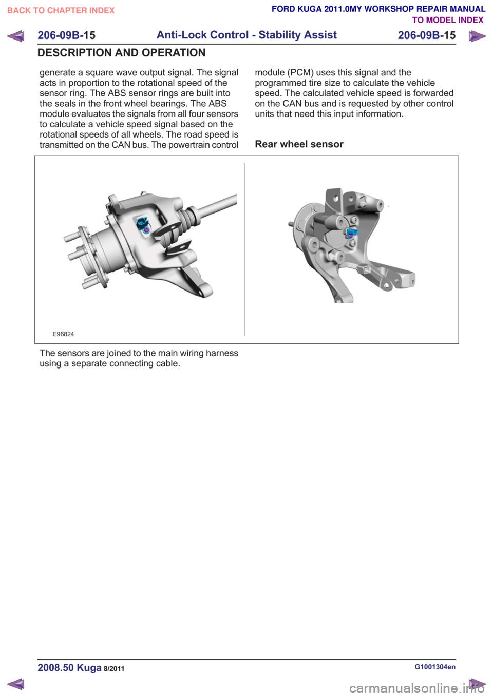
Rear wheel sensor
E96824
The sensors are joined to the main wiring harness
using a separate connecting cable.
G1001304en2008.50 Kuga8/2011
206-09B-
15
Anti-Lock Control - Stability Assist
206-09B- 15
DESCRIPTION AND OPERATION
TO MODEL INDEX
BACK TO CHAPTER INDEX
FORD KUGA 2011.0MY WORKSHOP REPAIR MANUAL
Page 1520 of 2057

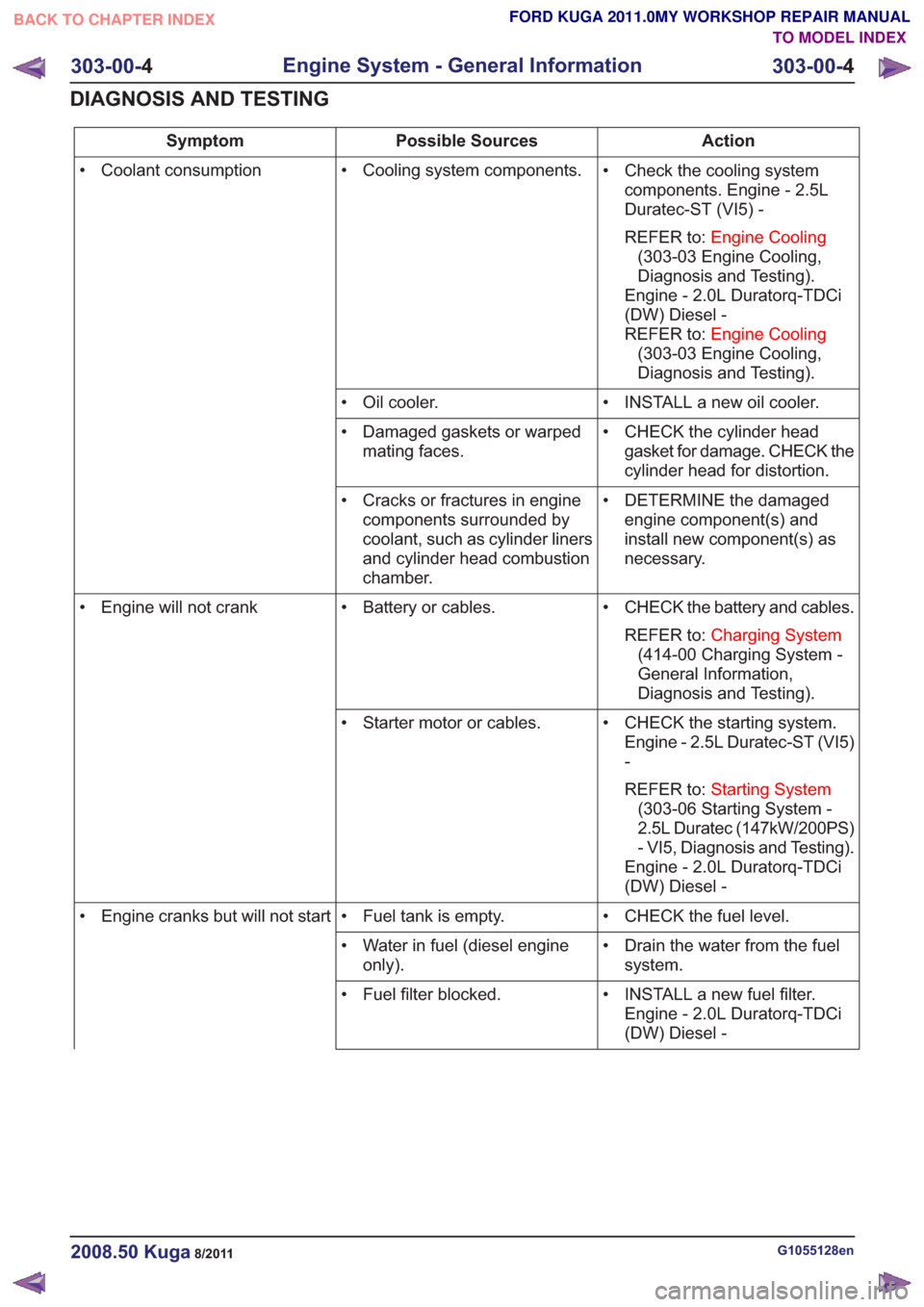
Action
Possible Sources
Symptom
• Check the cooling systemcomponents. Engine - 2.5L
Duratec-ST (VI5) -
REFER to: Engine Cooling
(303-03 Engine Cooling,
Diagnosis and Testing).
Engine - 2.0L Duratorq-TDCi
(DW) Diesel -
REFER to: Engine Cooling
(303-03 Engine Cooling,
Diagnosis and Testing).
• Cooling system components.
• Coolant consumption
• INSTALL a new oil cooler.
• Oil cooler.
• CHECK the cylinder headgasket for damage. CHECK the
cylinder head for distortion.
• Damaged gaskets or warped
mating faces.
• DETERMINE the damagedengine component(s) and
install new component(s) as
necessary.
• Cracks or fractures in engine
components surrounded by
coolant, such as cylinder liners
and cylinder head combustion
chamber.
• CHECK the battery and cables.REFER to: Charging System
(414-00 Charging System -
General Information,
Diagnosis and Testing).
• Battery or cables.
• Engine will not crank
• CHECK the starting system.Engine - 2.5L Duratec-ST (VI5)
-
REFER to: Starting System
(303-06 Starting System -
2.5L Duratec (147kW/200PS)
- VI5, Diagnosis and Testing).
Engine - 2.0L Duratorq-TDCi
(DW) Diesel -
• Starter motor or cables.
• CHECK the fuel level.
• Fuel tank is empty.
• Engine cranks but will not start
• Drain the water from the fuelsystem.
• Water in fuel (diesel engine
only).
• INSTALL a new fuel filter.Engine - 2.0L Duratorq-TDCi
(DW) Diesel -
• Fuel filter blocked.
G1055128en2008.50 Kuga8/2011
303-00-
4
Engine System - General Information
303-00- 4
DIAGNOSIS AND TESTING
TO MODEL INDEX
BACK TO CHAPTER INDEX
FORD KUGA 2011.0MY WORKSHOP REPAIR MANUAL