2011 FORD KUGA Throttle body
[x] Cancel search: Throttle bodyPage 1692 of 2057
SECTION 303-04A Fuel Charging and Controls— 2.5L Duratec
(147kW/200PS) - VI5
VEHICLE APPLICATION: 2008.50 Kuga
PA G E
CONTENTS
DESCRIPTION AND OPERATION
303-04A-2
Fuel Charging and Controls ........................................................................\
........................
DIAGNOSIS AND TESTING 303-04A-4
Fuel Charging and Controls ........................................................................\
........................
303-04A-4
Inspection and Verification ........................................................................\
..........................
303-04A-4
Symptom Chart ........................................................................\
...........................................
REMOVAL AND INSTALLATION 303-04A-22
Fuel Injectors ........................................................................\
..............................................
303-04A-23
(23 198 0)
Throttle Body ........................................................................\
..........................
303-04A-24
Fuel Rail ........................................................................\
......................................................
303-04A- 1
Fuel Charging and Controls
— 2.5L Duratec (147kW/200PS) -
VI5
303-04A- 1
.
TO MODEL INDEX
BACK TO CHAPTER INDEX
FORD KUGA 2011.0MY WORKSHOP REPAIR MANUAL
Page 1694 of 2057
Description
Item
Fuel Injectors
1
Valve
2
Fuel rail
3
Throttle body
4
Fuel tank to fuel rail fuel supply line
5
G510053en2008.50 Kuga8/2011
303-04A- 3
Fuel Charging and Controls
— 2.5L Duratec (147kW/200PS) -
VI5
303-04A- 3
DESCRIPTION AND OPERATION
TO MODEL INDEX
BACK TO CHAPTER INDEX
FORD KUGA 2011.0MY WORKSHOP REPAIR MANUAL
Page 1714 of 2057
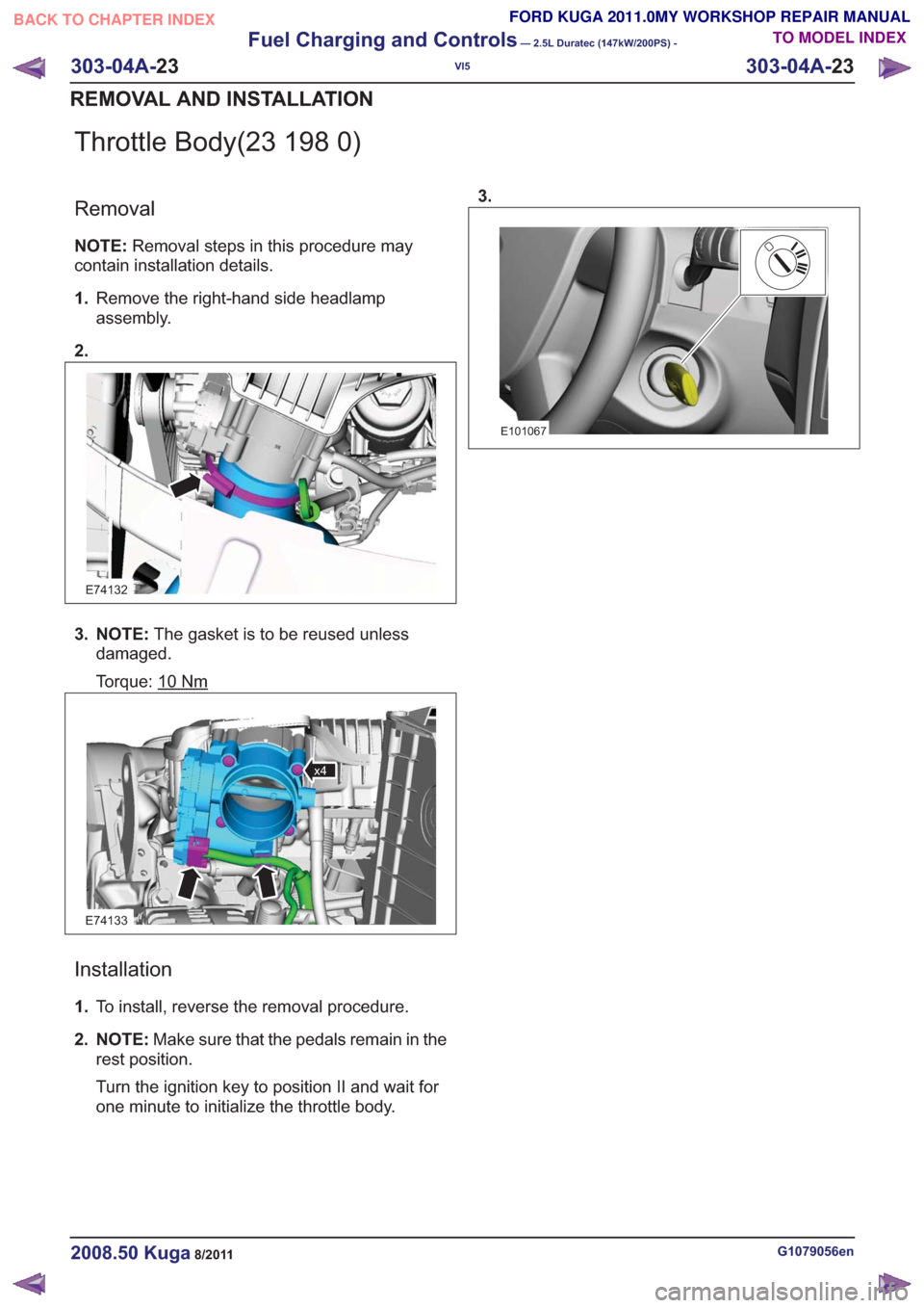
Throttle Body(23 198 0)
Removal
NOTE:Removal steps in this procedure may
contain installation details.
1. Remove the right-hand side headlamp
assembly.
2.
E74132
3. NOTE: The gasket is to be reused unless
damaged.
Torque: 10
Nm
E74133
x4
Installation
1. To install, reverse the removal procedure.
2. NOTE: Make sure that the pedals remain in the
rest position.
Turn the ignition key to position II and wait for
one minute to initialize the throttle body. 3.
E101067
G1079056en2008.50 Kuga8/2011
303-04A-
23
Fuel Charging and Controls
— 2.5L Duratec (147kW/200PS) -
VI5
303-04A- 23
REMOVAL AND INSTALLATION
TO MODEL INDEX
BACK TO CHAPTER INDEX
FORD KUGA 2011.0MY WORKSHOP REPAIR MANUAL
Page 1767 of 2057
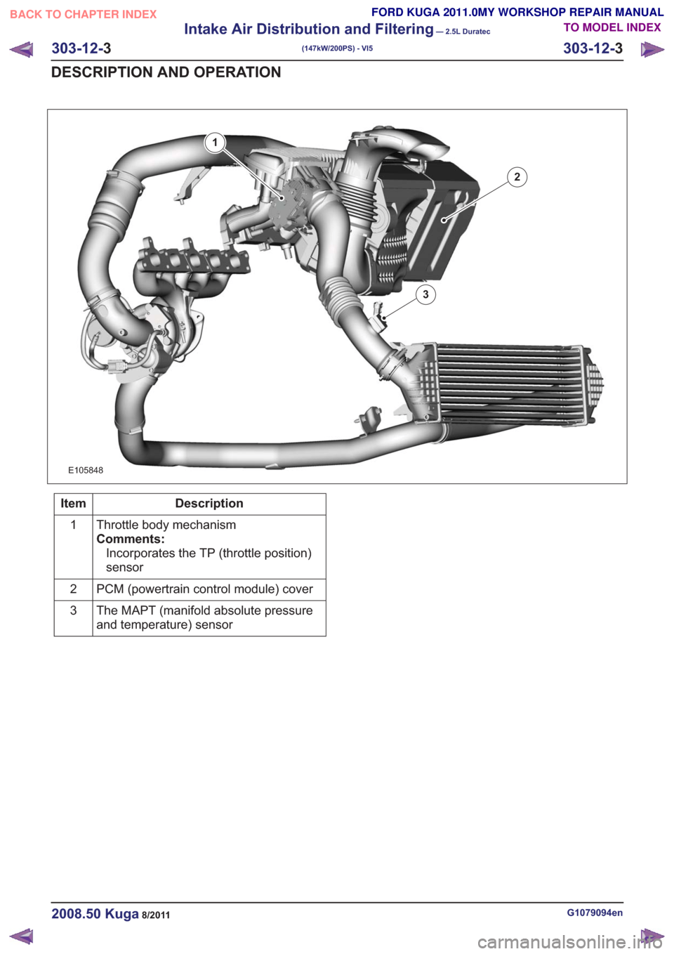
E105848
1
2
3
Description
Item
Throttle body mechanism
Comments:Incorporates the TP (throttle position)
sensor
1
PCM (powertrain control module) cover
2
The MAPT (manifold absolute pressure
and temperature) sensor
3
G1079094en2008.50 Kuga8/2011
303-12-
3
Intake Air Distribution and Filtering
— 2.5L Duratec
(147kW/200PS) - VI5
303-12- 3
DESCRIPTION AND OPERATION
TO MODEL INDEX
BACK TO CHAPTER INDEX
FORD KUGA 2011.0MY WORKSHOP REPAIR MANUAL
Page 1817 of 2057
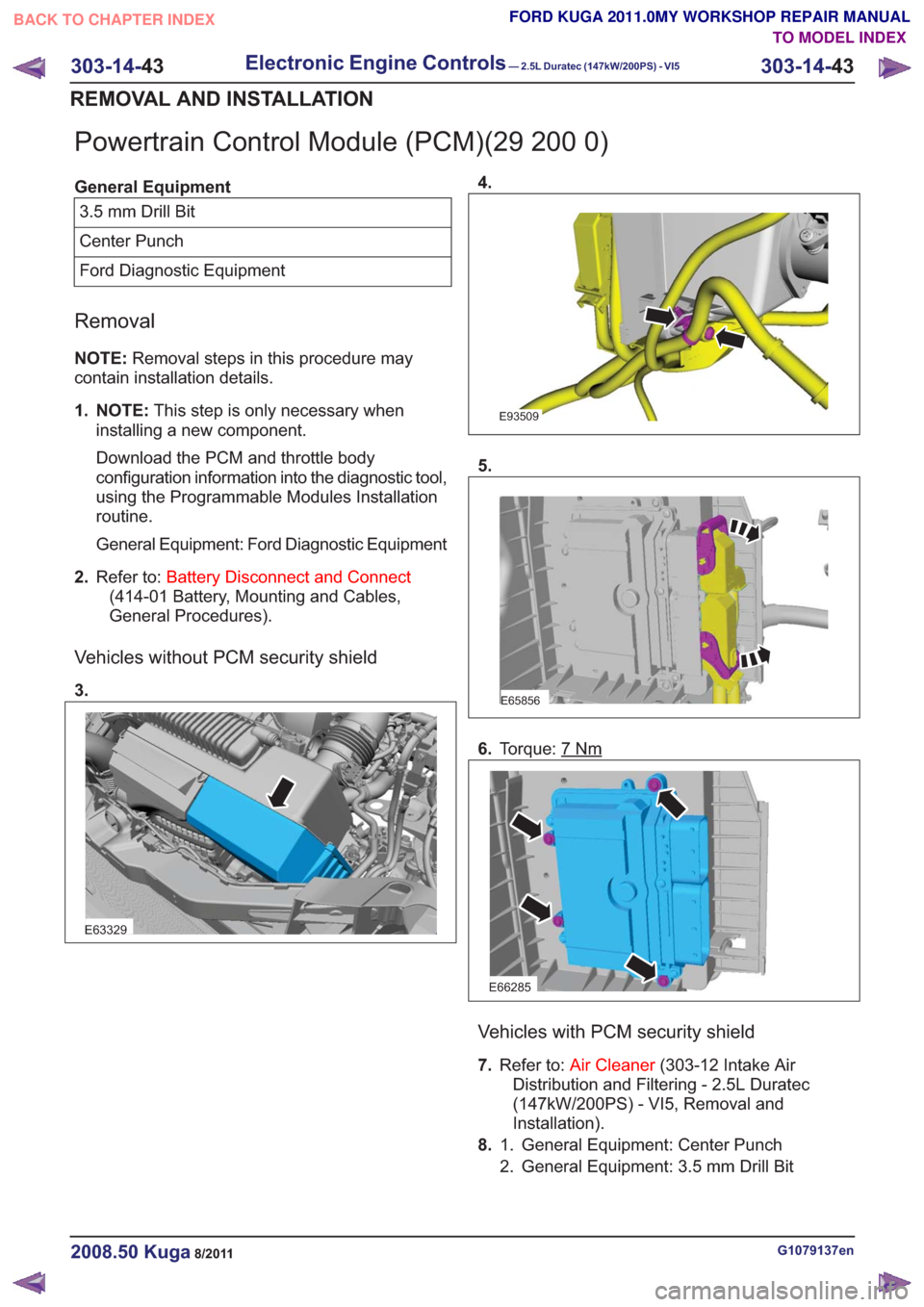
Powertrain Control Module (PCM)(29 200 0)
General Equipment3.5 mm Drill Bit
Center Punch
Ford Diagnostic Equipment
Removal
NOTE: Removal steps in this procedure may
contain installation details.
1. NOTE: This step is only necessary when
installing a new component.
Download the PCM and throttle body
configuration information into the diagnostic tool,
using the Programmable Modules Installation
routine.
General Equipment: Ford Diagnostic Equipment
2. Refer to: Battery Disconnect and Connect
(414-01 Battery, Mounting and Cables,
General Procedures).
Vehicles without PCM security shield
3.
E63329
4.
E93509
5.
E65856
6. Torque: 7Nm
E66285
Vehicles with PCM security shield
7.Refer to: Air Cleaner (303-12 Intake Air
Distribution and Filtering - 2.5L Duratec
(147kW/200PS) - VI5, Removal and
Installation).
8. General Equipment: Center Punch
1.
2. General Equipment: 3.5 mm Drill Bit
G1079137en2008.50 Kuga8/2011
303-14- 43
Electronic Engine Controls— 2.5L Duratec (147kW/200PS) - VI5303-14-
43
REMOVAL AND INSTALLATION
TO MODEL INDEX
BACK TO CHAPTER INDEX
FORD KUGA 2011.0MY WORKSHOP REPAIR MANUAL
Page 1818 of 2057
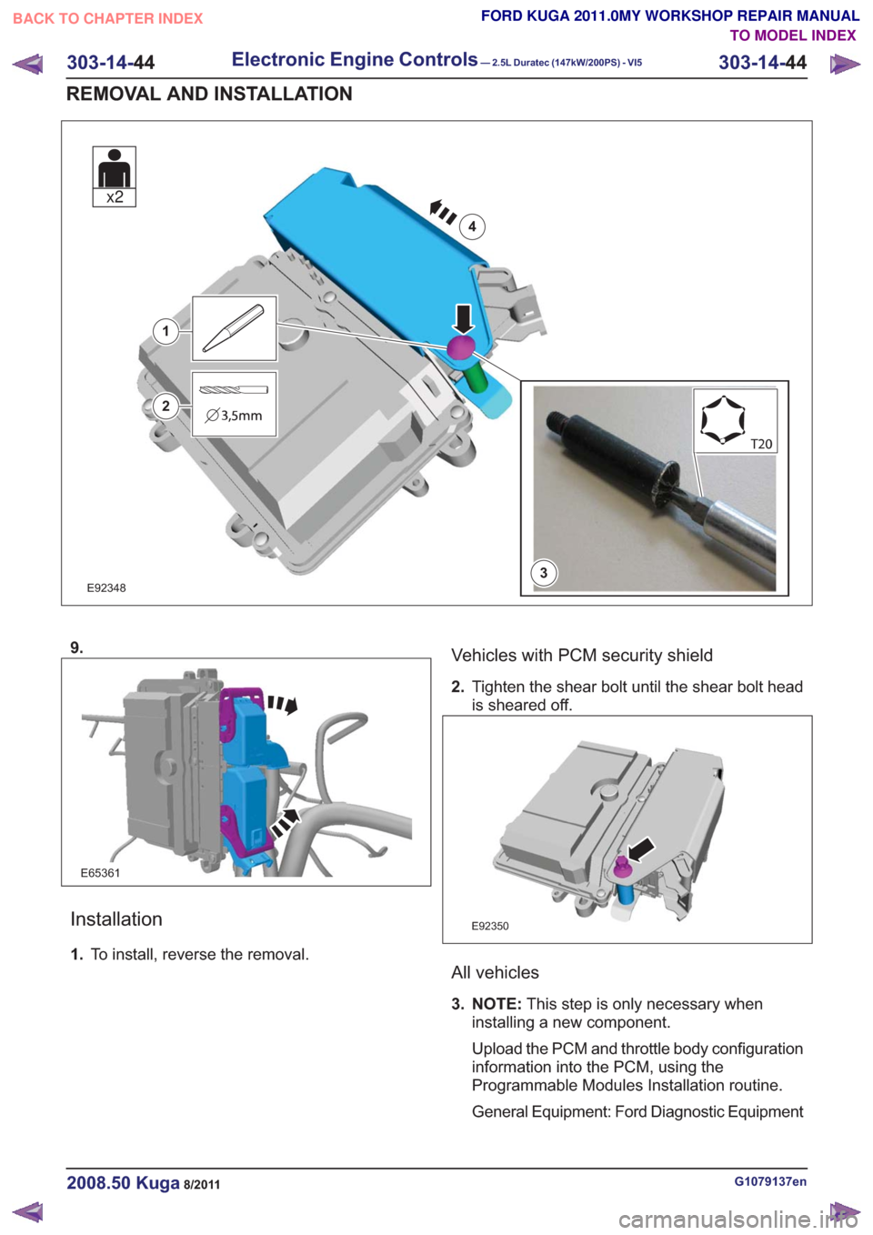
E923483
1
2
4
x2
9.
E65361
Installation
1.To install, reverse the removal.
Vehicles with PCM security shield
2.Tighten the shear bolt until the shear bolt head
is sheared off.
E92350
All vehicles
3. NOTE: This step is only necessary when
installing a new component.
Upload the PCM and throttle body configuration
information into the PCM, using the
Programmable Modules Installation routine.
General Equipment: Ford Diagnostic Equipment
G1079137en2008.50 Kuga8/2011
303-14- 44
Electronic Engine Controls— 2.5L Duratec (147kW/200PS) - VI5303-14-
44
REMOVAL AND INSTALLATION
TO MODEL INDEX
BACK TO CHAPTER INDEX
FORD KUGA 2011.0MY WORKSHOP REPAIR MANUAL
Page 2002 of 2057
Acceleration Control
Inspection and Verification
1. Verify the customer concern.
2. Visually inspect for obvious signs of mechanicalor electrical damage.
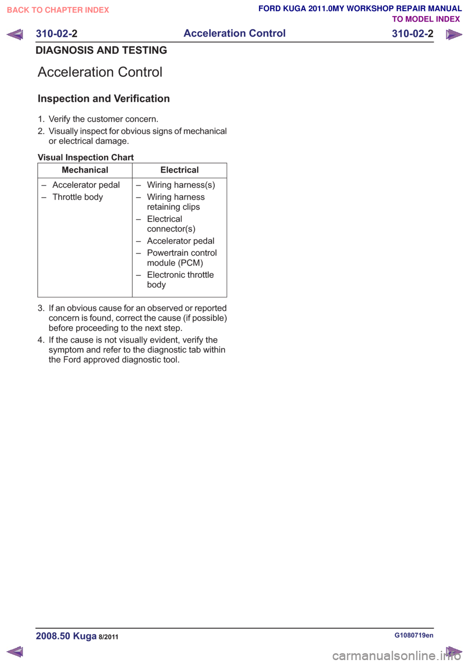
Visual Inspection Chart
Electrical
Mechanical
– Wiring harness(s)
– Wiring harnessretaining clips
– Electrical connector(s)
– Accelerator pedal
– Powertrain control module (PCM)
– Electronic throttle body
– Accelerator pedal
– Throttle body
3. If an obvious cause for an observed or reported concern is found, correct the cause (if possible)
before proceeding to the next step.
4. If the cause is not visually evident, verify the symptom and refer to the diagnostic tab within
the Ford approved diagnostic tool.
G1080719en2008.50 Kuga8/2011
310-02- 2
Acceleration Control
310-02- 2
DIAGNOSIS AND TESTING
TO MODEL INDEX
BACK TO CHAPTER INDEX
FORD KUGA 2011.0MY WORKSHOP REPAIR MANUAL
Page 2007 of 2057
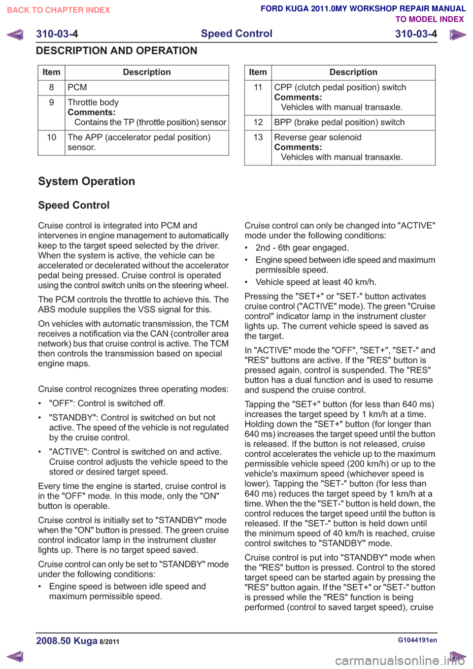
Description
Item
PCM
8
Throttle body
Comments:Contains the TP (throttle position) sensor
9
The APP (accelerator pedal position)
sensor.
10Description
Item
CPP (clutch pedal position) switch
Comments:Vehicles with manual transaxle.
11
BPP (brake pedal position) switch
12
Reverse gear solenoid
Comments:Vehicles with manual transaxle.
13
System Operation
Speed Control
Cruise control is integrated into PCM and
intervenes in engine management to automatically
keep to the target speed selected by the driver.
When the system is active, the vehicle can be
accelerated or decelerated without the accelerator
pedal being pressed. Cruise control is operated
using the control switch units on the steering wheel.
The PCM controls the throttle to achieve this. The
ABS module supplies the VSS signal for this.
On vehicles with automatic transmission, the TCM
receives a notification via the CAN (controller area
network) bus that cruise control is active. The TCM
then controls the transmission based on special
engine maps.
Cruise control recognizes three operating modes:
• "OFF": Control is switched off.
• "STANDBY": Control is switched on but not
active. The speed of the vehicle is not regulated
by the cruise control.
• "ACTIVE": Control is switched on and active. Cruise control adjusts the vehicle speed to the
stored or desired target speed.
Every time the engine is started, cruise control is
in the "OFF" mode. In this mode, only the "ON"
button is operable.
Cruise control is initially set to "STANDBY" mode
when the "ON" button is pressed. The green cruise
control indicator lamp in the instrument cluster
lights up. There is no target speed saved.
Cruise control can only be set to "STANDBY" mode
under the following conditions:
• Engine speed is between idle speed and maximum permissible speed. Cruise control can only be changed into "ACTIVE"
mode under the following conditions:
• 2nd - 6th gear engaged.
• Engine speed between idle speed and maximum
permissible speed.
• Vehicle speed at least 40 km/h.
Pressing the "SET+" or "SET-" button activates
cruise control ("ACTIVE" mode). The green "Cruise
control" indicator lamp in the instrument cluster
lights up. The current vehicle speed is saved as
the target.
In "ACTIVE" mode the "OFF", "SET+", "SET-" and
"RES" buttons are active. If the "RES" button is
pressed again, control is suspended. The "RES"
button has a dual function and is used to resume
and suspend the cruise control.
Tapping the "SET+" button (for less than 640 ms)
increases the target speed by 1 km/h at a time.
Holding down the "SET+" button (for longer than
640 ms) increases the target speed until the button
is released. If the button is not released, cruise
control accelerates the vehicle up to the maximum
permissible vehicle speed (200 km/h) or up to the
vehicle's maximum speed (whichever speed is
lower). Tapping the "SET-" button (for less than
640 ms) reduces the target speed by 1 km/h at a
time. When the the "SET-" button is held down, the
control reduces the target speed until the button is
released. If the "SET-" button is held down until
the minimum speed of 40 km/h is reached, cruise
control switches to "STANDBY" mode.
Cruise control is put into "STANDBY" mode when
the "RES" button is pressed. Control to the stored
target speed can be started again by pressing the
"RES" button again. If the "SET+" or "SET-" button
is pressed while the "RES" function is being
performed (control to saved target speed), cruise
G1044191en2008.50 Kuga8/2011
310-03- 4
Speed Control
310-03- 4
DESCRIPTION AND OPERATION
TO MODEL INDEX
BACK TO CHAPTER INDEX
FORD KUGA 2011.0MY WORKSHOP REPAIR MANUAL