Page 1520 of 2057

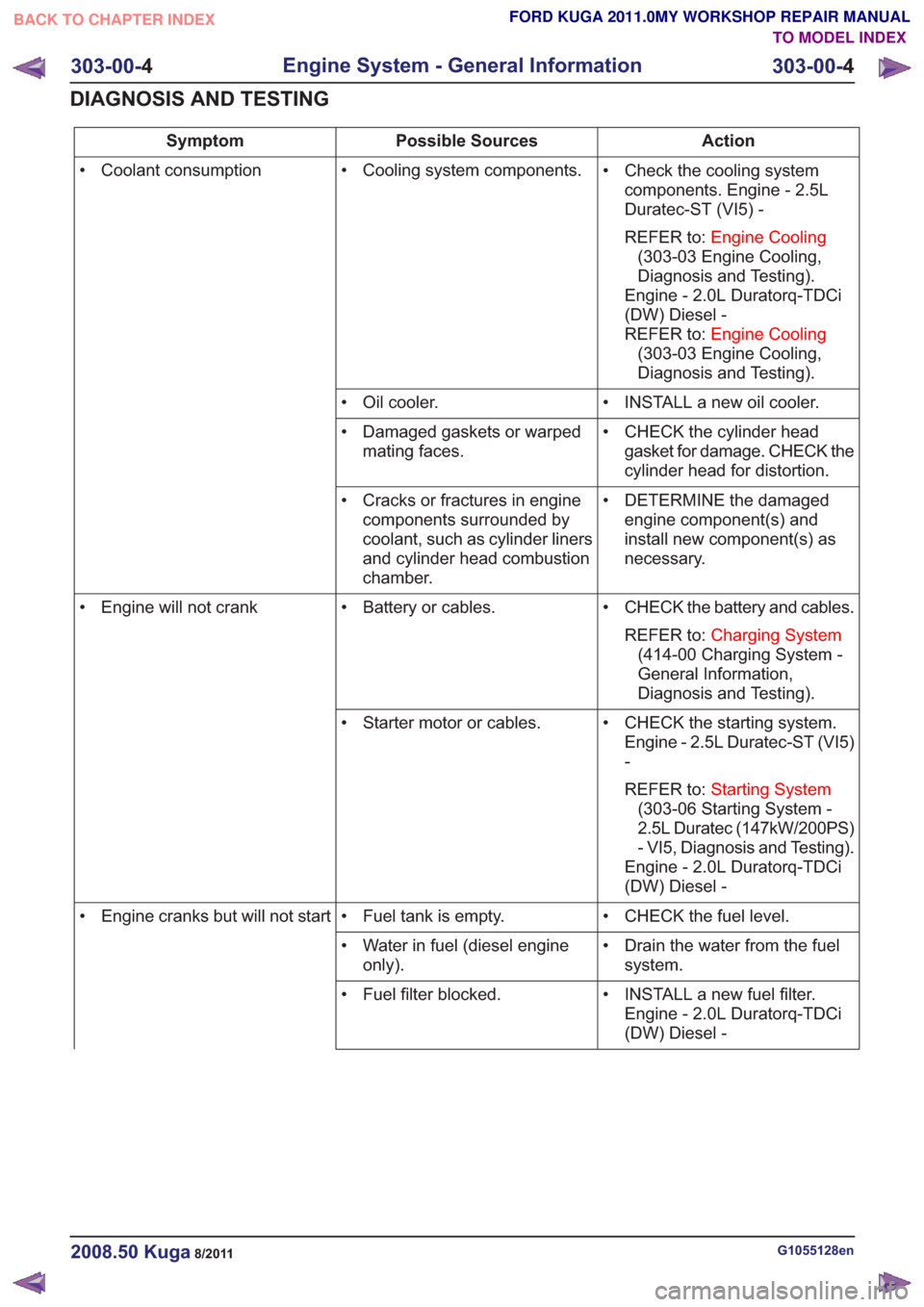
Action
Possible Sources
Symptom
• Check the cooling systemcomponents. Engine - 2.5L
Duratec-ST (VI5) -
REFER to: Engine Cooling
(303-03 Engine Cooling,
Diagnosis and Testing).
Engine - 2.0L Duratorq-TDCi
(DW) Diesel -
REFER to: Engine Cooling
(303-03 Engine Cooling,
Diagnosis and Testing).
• Cooling system components.
• Coolant consumption
• INSTALL a new oil cooler.
• Oil cooler.
• CHECK the cylinder headgasket for damage. CHECK the
cylinder head for distortion.
• Damaged gaskets or warped
mating faces.
• DETERMINE the damagedengine component(s) and
install new component(s) as
necessary.
• Cracks or fractures in engine
components surrounded by
coolant, such as cylinder liners
and cylinder head combustion
chamber.
• CHECK the battery and cables.REFER to: Charging System
(414-00 Charging System -
General Information,
Diagnosis and Testing).
• Battery or cables.
• Engine will not crank
• CHECK the starting system.Engine - 2.5L Duratec-ST (VI5)
-
REFER to: Starting System
(303-06 Starting System -
2.5L Duratec (147kW/200PS)
- VI5, Diagnosis and Testing).
Engine - 2.0L Duratorq-TDCi
(DW) Diesel -
• Starter motor or cables.
• CHECK the fuel level.
• Fuel tank is empty.
• Engine cranks but will not start
• Drain the water from the fuelsystem.
• Water in fuel (diesel engine
only).
• INSTALL a new fuel filter.Engine - 2.0L Duratorq-TDCi
(DW) Diesel -
• Fuel filter blocked.
G1055128en2008.50 Kuga8/2011
303-00-
4
Engine System - General Information
303-00- 4
DIAGNOSIS AND TESTING
TO MODEL INDEX
BACK TO CHAPTER INDEX
FORD KUGA 2011.0MY WORKSHOP REPAIR MANUAL
Page 1529 of 2057

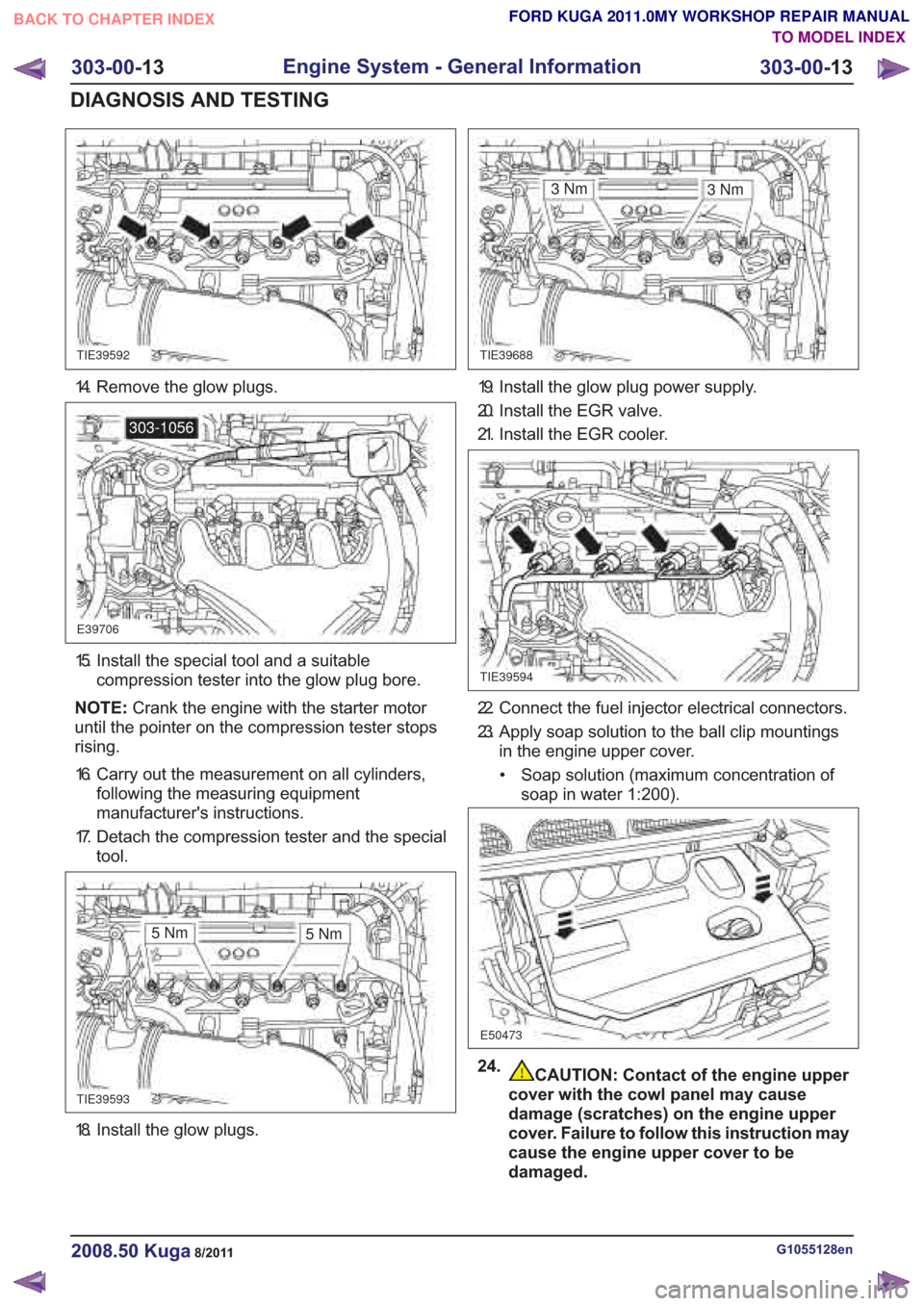
18. Install the glow plugs.
CAUTION: Contact of the engine upper
cover with the cowl panel may cause
damage (scratches) on the engine upper
cover. Failure to follow this instruction may
cause the engine upper cover to be
damaged.
G1055128en2008.50 Kuga8/2011
303-00- 13
Engine System - General Information
303-00- 13
DIAGNOSIS AND TESTING
FORD KUGA 2011.0MY WORKSHOP REPAIR MANUAL
TO MODEL INDEX
BACK TO CHAPTER INDEX
TIE39592TIE39688
E39706
303-1056
TIE39593
3Nm
TIE39594
E50473
3Nm
5Nm 5Nm
14. Remove the glow plugs.
15. Install the special tool and a suitable
compression tester into the glow plug bore.
NOTE: Crank the engine with the starter motor
until the pointer on the compression tester stops
rising.
16. Carry out the measurement on all cylinders, following the measuring equipment
manufacturer's instructions.
17. Detach the compression tester and the special tool.
19. Install the glow plug power supply.
20. Install the EGR valve.
21. Install the EGR cooler.
22. Connect the fuel injector electrical connectors.
23. Apply soap solution to the ball clip mountingsin the engine upper cover.
• Soap solution (maximum concentration of soap in water 1:200).
24.
Page 1768 of 2057

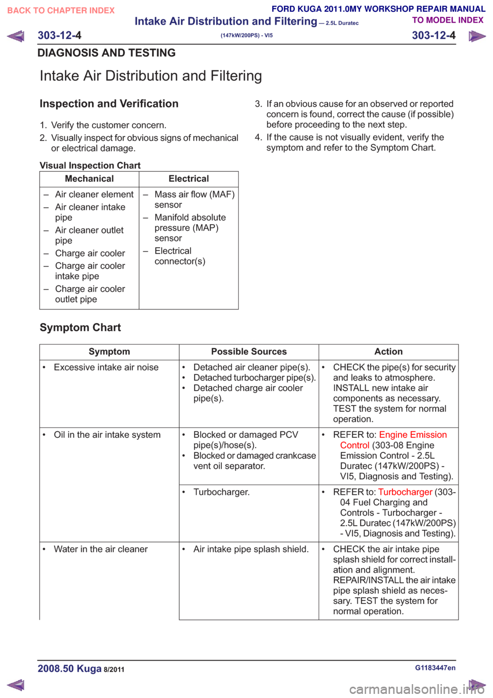
Intake Air Distribution and Filtering
Inspection and Verification
1. Verify the customer concern.
2. Visually inspect for obvious signs of mechanicalor electrical damage.
Visual Inspection Chart
Electrical
Mechanical
– Mass air flow (MAF)sensor
– Manifold absolute pressure (MAP)
sensor
– Electrical connector(s)
– Air cleaner element
– Air cleaner intake
pipe
– Air cleaner outlet pipe
– Charge air cooler
– Charge air cooler intake pipe
– Charge air cooler outlet pipe 3. If an obvious cause for an observed or reported
concern is found, correct the cause (if possible)
before proceeding to the next step.
4. If the cause is not visually evident, verify the symptom and refer to the Symptom Chart.
Symptom Chart
Action
Possible Sources
Symptom
• CHECK the pipe(s) for securityand leaks to atmosphere.
INSTALL new intake air
components as necessary.
TEST the system for normal
operation.
• Detached air cleaner pipe(s).
• Detached turbocharger pipe(s).
• Detached charge air cooler
pipe(s).
• Excessive intake air noise
• REFER to:Engine Emission
Control (303-08 Engine
Emission Control - 2.5L
Duratec (147kW/200PS) -
VI5, Diagnosis and Testing).
• Blocked or damaged PCV
pipe(s)/hose(s).
• Blocked or damaged crankcase vent oil separator.
• Oil in the air intake system
• REFER to:Turbocharger(303-
04 Fuel Charging and
Controls - Turbocharger -
2.5L Duratec (147kW/200PS)
- VI5, Diagnosis and Testing).
• Turbocharger.
• CHECK the air intake pipesplash shield for correct install-
ation and alignment.
REPAIR/INSTALL the air intake
pipe splash shield as neces-
sary. TEST the system for
normal operation.
• Air intake pipe splash shield.
• Water in the air cleaner
G1183447en2008.50 Kuga8/2011
303-12- 4
Intake Air Distribution and Filtering
— 2.5L Duratec
(147kW/200PS) - VI5
303-12- 4
DIAGNOSIS AND TESTING
TO MODEL INDEX
BACK TO CHAPTER INDEX
FORD KUGA 2011.0MY WORKSHOP REPAIR MANUAL