2011 FORD KUGA buttons
[x] Cancel search: buttonsPage 267 of 2057
Action
Battery Tester Reading WARNING: Do not recharge the battery.
Make sure that the surface charge was removed. A "REPLACE BATTERY" result could also mean
a poor connection between the battery cables and the battery. Check the connections are OK and
retest. If the result remains the same, INSTALL a NEW battery
REFER to: Battery(414-01 Battery, Mounting and
Cables, Removal and Installation).
REPLACE BATTERY or BAD CELL BATTERY
In addition it is advisable to check the vehicle electrical system. Check that the generator is functioning
correctly and the vehicle does not have an excessive key-off load (in general this should be under
20mA after 40 minutes of key off).
Midtronics EXP-1050 Battery Tester Test
Code
At the end of the test, use the arrow keys to scroll
down the screens to see additional information.
One of these is the TEST CODE.
The TEST CODE has 11 digits, for example:
0021U-B88WKX.
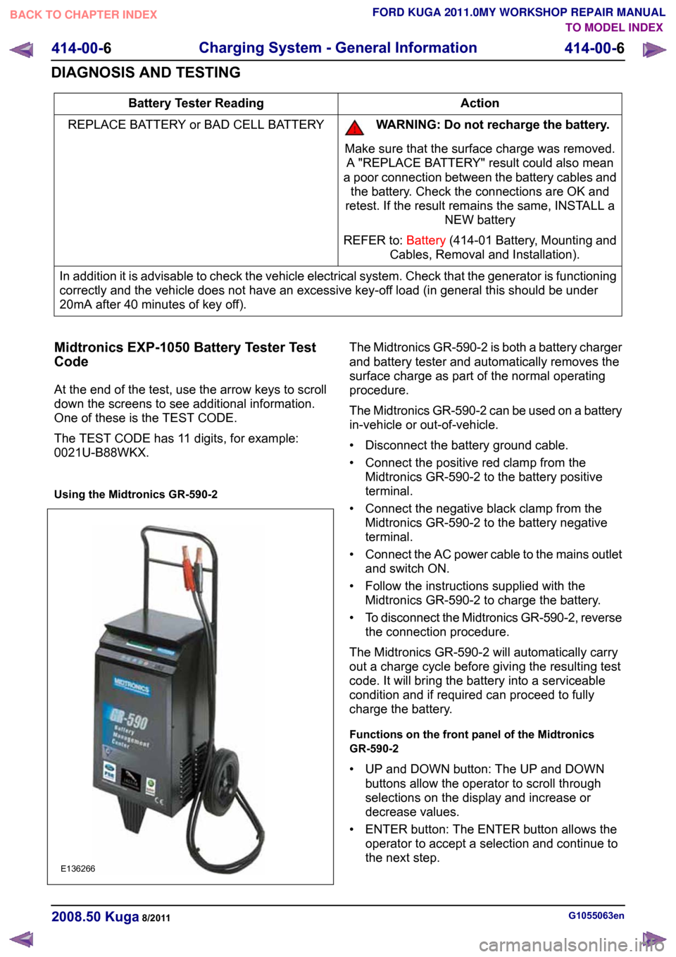
Using the Midtronics GR-590-2 The Midtronics GR-590-2 is both a battery charger
and battery tester and automatically removes the
surface charge as part of the normal operating
procedure.
The Midtronics GR-590-2 can be used on a battery
in-vehicle or out-of-vehicle.
• Disconnect the battery ground cable.
• Connect the positive red clamp from the
Midtronics GR-590-2 to the battery positive
terminal.
• Connect the negative black clamp from the Midtronics GR-590-2 to the battery negative
terminal.
• Connect the AC power cable to the mains outlet
and switch ON.
• Follow the instructions supplied with the Midtronics GR-590-2 to charge the battery.
• To disconnect the Midtronics GR-590-2, reverse
the connection procedure.
The Midtronics GR-590-2 will automatically carry
out a charge cycle before giving the resulting test
code. It will bring the battery into a serviceable
condition and if required can proceed to fully
charge the battery.
Functions on the front panel of the Midtronics
GR-590-2
• UP and DOWN button: The UP and DOWN buttons allow the operator to scroll through
selections on the display and increase or
decrease values.
• ENTER button: The ENTER button allows the operator to accept a selection and continue to
the next step. G1055063en
2008.50 Kuga 8/2011 414-00-6
Charging System - General Information
414-00-6
DIAGNOSIS AND TESTINGTO MODEL INDEX
BACK TO CHAPTER INDEX
FORD KUGA 2011.0MY WORKSHOP REPAIR MANUALE136266
Page 288 of 2057

Audio System
Refer to Wiring Diagrams Section 415-01, for
schematic and connector information.
Refer to Wiring Diagrams Section 415-03, for
schematic and connector information.
General Equipment
The Ford approved diagnostic tool
Inspection and Verification
NOTE: If the keycode is entered incorrectly 3 times,
the system will allow the next keycode in 30
minutes. After entering the keycode the 10th time
incorrectly the system will lock out. The component
can only be unlocked by the manufacturer.
1. Verify the customer concern.
2. Visually inspect for obvious signs of mechanical
or electrical damage.
Visual Inspection Chart Electrical
Mechanical
– Fuse(s)
– Wiring harness
– Electricalconnector(s)
– Audio unit
– Audio control switch (if equipped)
– CD changer
– Central junction box (CJB)
– Audio unit
– Antenna
– Foreign objects
contacting speaker
– Trim poorly fitted/resonance
– Audio control switch (if equipped)
– Compact disc (CD) changer
3. If an obvious cause for an observed or reported concern is found, correct the cause (if possible)
before proceeding to the next step.
4. If the cause is not visually evident, verify the symptom and refer to the Self-Diagnostic Mode.
Self-Diagnostic Mode - Low Series
Audio Unit
NOTE: The audio unit must be in radio mode
before entering the Self-Diagnostic Mode.
1. To enter the audio unit Self-Diagnostic Mode, switch the audio unit ON. Within four seconds
depress the preset buttons 3 and 6 together.
2. Release the preset buttons 3 and 6 and the audio unit will enter the Self-Diagnostic Mode. 3.
The Self-Diagnostic Mode will automatically stop
after one iterration or to interrupt it , switch the
audio unit OFF.
Self-Diagnostic Mode Circuit Tested
Message Displayed
Right hand front woofercircuit
1. 4CH RF low
Right hand fronttweeter circuit.
2. 4CH RF high
Left hand front woofercircuit.
3. 4CH LF low
Left hand front tweetercircuit.
3. 4CH LF High
Right hand rear woofercircuit
1. 4CH RR low
Right hand rear tweetercircuit
2. 4CH RR high
Left hand rear woofercircuit
3. 4CH LR low
Left hand rear tweetercircuit.
3. 4CH LR High
Antenna connection
Seek 87.5 - 108.0
4. If the cause is not evident after the Self-Diagnostic Mode, connect the Ford
approved diagnostic tool to the data link
connector (DLC).
Self-Diagnostic Mode - High Series
Audio Unit GEN 2
NOTE: The audio unit must be in radio mode
before entering the Self-Diagnostic Mode.
1. To enter the audio unit Self-Diagnostic Mode, switch the audio unit ON. Within four seconds
depress the preset button 3 and 6 together.
2. Release the preset button 3 and 6 and the audio
unit will enter the Self-Diagnostic Mode.
3. The Self-Diagnostic Mode will automatically stop
after one iterration or to interrupt it , switch the
audio unit OFF.
Self-Diagnostic Mode Circuit Tested
Message Displayed
Right hand front woofercircuit
RF speaker 600Hz G1055068en
2008.50 Kuga 8/2011 415-00-2
Information and Entertainment System -
General Information
415-00-2
DIAGNOSIS AND TESTINGTO MODEL INDEX
BACK TO CHAPTER INDEX
FORD KUGA 2011.0MY WORKSHOP REPAIR MANUAL
Page 299 of 2057

Audio System – Overview
Keycode entry - vehicle with standard
audio system
The keycode is entered via the MENU button and
the arrow buttons. The keycode is then confirmed
with the rotary/pushbutton in the middle of the unit.
Only a limited number of attempts to enter the
correct keycode are allowed. The number of
attempts already made is shown in the display.
Following every subsequent unsuccessful attempt,
an uninterrupted waiting period must be observed
before a further attempt can be made.
The display then shows "WAIT XX" and counts
down to "0", provided the ignition remains switched
on. Once this time has expired, a new attempt can
be made to enter the keycode.
After a certain number of unsuccessful attempts
at entering the keycode, the display will show
"LOCKED" or "SAFE". The customer will now be
unable to switch on the device.
The authorized Ford dealer can remove the lock
and can make up to three further attempts.
Vehicle Identification Number (VID) -
entry - vehicle with standard audio
system
It is often extremely difficult to return stolen audio
units which have been seized by the police to their
owners.
Therefore, many Ford audio units offer the option
of, for example, entering a vehicle identification
number into the unit.
For Ford audio systems, the abbreviation VID is
used to refer to the Vehicle Identification Number.
The VIN (chassis number) or, for instance, the number plate number can be entered and this
fulfills the security function.
The VIN is programmed ex works. If the unit is
replaced, the VIN is automatically transferred by
the diagnostics system during configuration.
Self-check routine - vehicles with
standard audio system.
The audio unit must be in radio mode before
entering the Self-Diagnostic Mode.
To enter the audio unit Self-Diagnostic Mode,
switch the audio unit ON. Press pre-set buttons 3
and 6 simultaneously and then release them again.
Keycode entry - vehicles with upgraded
audio system
The station keys are used to enter the keycode.
Station key 5 is used to confirm the keycode.
Only a limited number of attempts to enter the
correct keycode are allowed. The number of
attempts already made is shown in the display.
After the second unsuccessful attempt, the person
entering the keycode will have to wait for an
uninterrupted period of time before making the next
attempt.
The display then shows "WAIT XX" and counts
down to "0", provided the ignition remains switched
on. Once this time has expired, a new attempt can
be made to enter the keycode.
After a certain number of unsuccessful attempts
at entering the keycode, the display will show
"LOCKED" or "SAFE". The customer will now be
unable to switch on the device.
G1055645en
2008.50 Kuga 8/2011 415-01-3
Information and Entertainment System
415-01-3
DESCRIPTION AND OPERATIONTO MODEL INDEX
BACK TO CHAPTER INDEX
FORD KUGA 2011.0MY WORKSHOP REPAIR MANUALE99206 E99207
Page 1865 of 2057
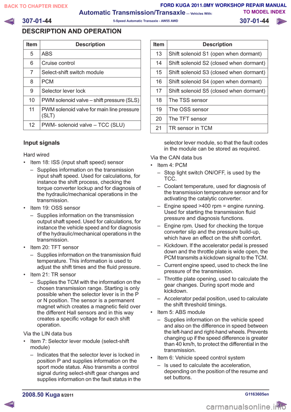
Description
Item
ABS5
Cruise control
6
Select-shift switch module
7
PCM
8
Selector lever lock
9
PWM solenoid valve – shift pressure (SLS)
10
PWM solenoid valve for main line pressure
(SLT)
11
PWM- solenoid valve – TCC (SLU)
12Description
Item
Shift solenoid S1 (open when dormant)
13
Shift solenoid S2 (closed when dormant)
14
Shift solenoid S3 (closed when dormant)
15
Shift solenoid S4 (open when dormant)
16
Shift solenoid S5 (closed when dormant)
17
The TSS sensor
18
The OSS sensor
19
The TFT sensor
20
TR sensor in TCM
21
Input signals
Hard wired
• Item 18: ISS (input shaft speed) sensor
– Supplies information on the transmissioninput shaft speed. Used for calculations, for
instance the shift process, checking the
torque converter lockup and for diagnosis of
the hydraulic/mechanical operations in the
transmission.
• Item 19: OSS sensor – Supplies information on the transmissionoutput shaft speed. Used for calculations, for
instance the vehicle speed and for diagnosis
of the hydraulic/mechanical operations in the
transmission.
• Item 20: TFT sensor – Supplies information on the transmission fluidtemperature. This information is used to
adjust the shift times and the fluid pressure.
• Item 21: TR sensor – Supplies the TCM with the information on thechosen transmission range. Starting is only
possible when the selector lever is in the P
or N position. The sensor is a permanent
magnet which creates a magnetic field over
the different Hall sensors and in this way
creates a specific voltage for each shift
operation.
Via the LIN data bus
• Item 7: Selector lever module (select-shift module)
– Indicates that the selector lever is locked inposition P and supplies information on the
sport mode status. Also transmits a control
signal during select-shift gear changes and
supplies information on the fault status in the selector lever module, so that the fault codes
in the module can be stored as required.
Via the CAN data bus
• Item 4: PCM – Stop light switch ON/OFF, is used by theTCC.
– Coolant temperature, used for diagnosis of the transmission temperature sensor and for
activating the catalytic converter.
– Engine speed >400 rpm = engine running. Used for starting the transmission fluid
pressure and diagnosis functions.
– Engine rpm. Used for checking the torque converter slip and the pressure build-up,
which have an effect on the shift comfort.
– Kickdown. If the accelerator pedal is pressed down and the throttle plate is wide open, the
PCM transmits a kickdown signal to the TCM.
– Current engine speed, used to check the line pressure of the transmission.
– Throttle plate opening, used to calculate the gear changes. During sport mode and
kickdown.
– Accelerator pedal position, used to calculate the shift threshold timings.
• Item 5: ABS module – Supplies information on the vehicle speedand also on the difference in speed between
the left-hand and right-hand wheels. Prevents
changing up if the speed difference is greater
than 40 km/h, to protect the differential in the
transmission.
• Item 6: Vehicle speed control system – Is used to calculate the acceleration,depending on the position of the resume and
set buttons.
G1163605en2008.50 Kuga8/2011
307-01- 44
Automatic Transmission/Transaxle
— Vehicles With:
5-Speed Automatic Transaxle - AW55 AWD
307-01- 44
DESCRIPTION AND OPERATION
TO MODEL INDEX
BACK TO CHAPTER INDEX
FORD KUGA 2011.0MY WORKSHOP REPAIR MANUAL
Page 2005 of 2057
Speed Control – Overview
Speed Control
The cruise control system keeps the vehicle to a
target speed selected by the driver. The cruise
control system is controlled by the PCM (powertrain
control module)
WARNING: The cruise control system may
not be used in heavy traffic, on winding
roads or on a slippery road surface.
To remove the buttons for the cruise control
system, the airbag must be removed. The buttons
for the two control switch units cannot be replaced
individually.
G1015505en2008.50 Kuga8/2011
310-03- 2
Speed Control
310-03- 2
DESCRIPTION AND OPERATION
TO MODEL INDEX
BACK TO CHAPTER INDEX
FORD KUGA 2011.0MY WORKSHOP REPAIR MANUAL
Page 2007 of 2057
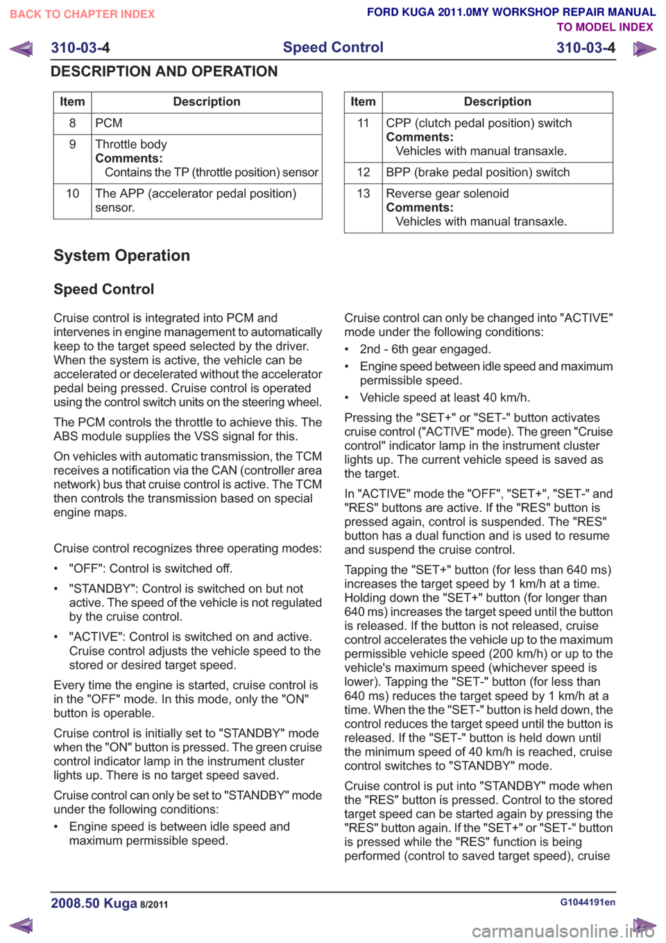
Description
Item
PCM
8
Throttle body
Comments:Contains the TP (throttle position) sensor
9
The APP (accelerator pedal position)
sensor.
10Description
Item
CPP (clutch pedal position) switch
Comments:Vehicles with manual transaxle.
11
BPP (brake pedal position) switch
12
Reverse gear solenoid
Comments:Vehicles with manual transaxle.
13
System Operation
Speed Control
Cruise control is integrated into PCM and
intervenes in engine management to automatically
keep to the target speed selected by the driver.
When the system is active, the vehicle can be
accelerated or decelerated without the accelerator
pedal being pressed. Cruise control is operated
using the control switch units on the steering wheel.
The PCM controls the throttle to achieve this. The
ABS module supplies the VSS signal for this.
On vehicles with automatic transmission, the TCM
receives a notification via the CAN (controller area
network) bus that cruise control is active. The TCM
then controls the transmission based on special
engine maps.
Cruise control recognizes three operating modes:
• "OFF": Control is switched off.
• "STANDBY": Control is switched on but not
active. The speed of the vehicle is not regulated
by the cruise control.
• "ACTIVE": Control is switched on and active. Cruise control adjusts the vehicle speed to the
stored or desired target speed.
Every time the engine is started, cruise control is
in the "OFF" mode. In this mode, only the "ON"
button is operable.
Cruise control is initially set to "STANDBY" mode
when the "ON" button is pressed. The green cruise
control indicator lamp in the instrument cluster
lights up. There is no target speed saved.
Cruise control can only be set to "STANDBY" mode
under the following conditions:
• Engine speed is between idle speed and maximum permissible speed. Cruise control can only be changed into "ACTIVE"
mode under the following conditions:
• 2nd - 6th gear engaged.
• Engine speed between idle speed and maximum
permissible speed.
• Vehicle speed at least 40 km/h.
Pressing the "SET+" or "SET-" button activates
cruise control ("ACTIVE" mode). The green "Cruise
control" indicator lamp in the instrument cluster
lights up. The current vehicle speed is saved as
the target.
In "ACTIVE" mode the "OFF", "SET+", "SET-" and
"RES" buttons are active. If the "RES" button is
pressed again, control is suspended. The "RES"
button has a dual function and is used to resume
and suspend the cruise control.
Tapping the "SET+" button (for less than 640 ms)
increases the target speed by 1 km/h at a time.
Holding down the "SET+" button (for longer than
640 ms) increases the target speed until the button
is released. If the button is not released, cruise
control accelerates the vehicle up to the maximum
permissible vehicle speed (200 km/h) or up to the
vehicle's maximum speed (whichever speed is
lower). Tapping the "SET-" button (for less than
640 ms) reduces the target speed by 1 km/h at a
time. When the the "SET-" button is held down, the
control reduces the target speed until the button is
released. If the "SET-" button is held down until
the minimum speed of 40 km/h is reached, cruise
control switches to "STANDBY" mode.
Cruise control is put into "STANDBY" mode when
the "RES" button is pressed. Control to the stored
target speed can be started again by pressing the
"RES" button again. If the "SET+" or "SET-" button
is pressed while the "RES" function is being
performed (control to saved target speed), cruise
G1044191en2008.50 Kuga8/2011
310-03- 4
Speed Control
310-03- 4
DESCRIPTION AND OPERATION
TO MODEL INDEX
BACK TO CHAPTER INDEX
FORD KUGA 2011.0MY WORKSHOP REPAIR MANUAL
Page 2009 of 2057
• Parking brake switch.– The parking brake switch is hard-wired to theGEM. The parking brake switch sends a
signal to the GEM when the parking brake is
operated. The GEM activates the parking
brake indicator lamp in the instrument cluster.
If the parking brake indicator lamp is lit,
cruise control cannot be activated.
• Back-up light switch – The backup lamp switch is hard-wired to the GEM. The backup lamp switch sends a signal
to the GEM when reverse gear is engaged.
The GEM activates the reversing lamp.
Cruise control cannot be activated when
reverse gear is engaged.
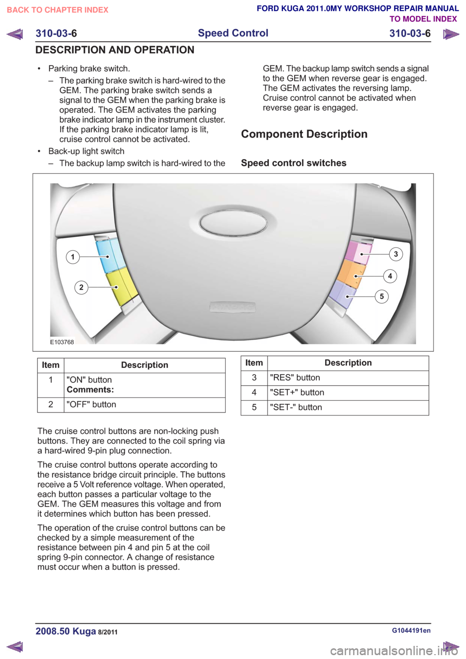
Component Description
Speed control switches
E103768
3
4
5
1
2
Description
Item
"ON" button
Comments:
1
"OFF" button
2Description
Item
"RES" button
3
"SET+" button
4
"SET-" button
5
The cruise control buttons are non-locking push
buttons. They are connected to the coil spring via
a hard-wired 9-pin plug connection.
The cruise control buttons operate according to
the resistance bridge circuit principle. The buttons
receive a 5 Volt reference voltage. When operated,
each button passes a particular voltage to the
GEM. The GEM measures this voltage and from
it determines which button has been pressed.
The operation of the cruise control buttons can be
checked by a simple measurement of the
resistance between pin 4 and pin 5 at the coil
spring 9-pin connector. A change of resistance
must occur when a button is pressed.
G1044191en2008.50 Kuga8/2011
310-03- 6
Speed Control
310-03- 6
DESCRIPTION AND OPERATION
TO MODEL INDEX
BACK TO CHAPTER INDEX
FORD KUGA 2011.0MY WORKSHOP REPAIR MANUAL
Page 2038 of 2057
Fault Memory Interrogation without
diagnostics unit - vehicles with
automatic temperature control
NOTE:On vehicles equipped with a DVD
navigation system with touchscreen, the fault
memory can only be interrogated using the Ford
diagnostic tool.
The climate control and heating system features
a on-board diagnosis function which can detect
and store both current permanent faults as well as
intermittent faults which have occurred during
normal operation of the vehicle. It is also possible
to read out these faults via the display on the
control panel of the climate control system. To read
out the fault memory, the ignition key must be
turned to the "ON" position and the battery voltage
must be between 9 V and 16 V.
To activate the on-board diagnosis at the control
panel for the climate control system, PRESS the
"OFF" and "FOOTWELL" buttons simultaneously
for exactly 2 seconds, then PRESS "AUTO" within
1.5 seconds. The on-board diagnosis which then
starts lasts a few seconds. An animated display
appears in the display of the control panel for the
climate control system during this time. Any faults
found are displayed on both displays of the control
panel for the climate control system in the form of
trouble codes.
To read out saved errors at the control panel for
the climate control system, PRESS the "OFF" and
"FOOTWELL" buttons simultaneously for exactly
2 seconds, then PRESS "HEAD AREA" within 1.5
seconds. Any stored faults are shown on the
display of the control panel for the climate control
system and should be noted for safety reasons.
By PRESSING the "DEFROST" button, the fault
memory is cleared and diagnosis mode is ended.
To end the diagnostic mode without clearing the
DTCs, PRESS any other operating button on the
control panel for the climate control system.
To read out the software version at the control
panel for the climate control system, PRESS the
"OFF" and "FOOTWELL" buttons simultaneously
for exactly 2 seconds, then PRESS "A/C" within
1.5 seconds. The software version is shown on the
display of the control panel for the climate control
system. The output mode can be exited by
PRESSING any button on the control panel for the
climate control system.
Switch over from Celsius to Fahrenheit
The switch from Celsius to Fahrenheit is performed
on the display of the instrument cluster and is then
transmitted via the CAN bus to the module of the
two-zone air conditioning system.
G1034945en2008.50 Kuga8/2011
412-01- 11
Climate Control
412-01- 11
DESCRIPTION AND OPERATION
TO MODEL INDEX
BACK TO CHAPTER INDEX
FORD KUGA 2011.0MY WORKSHOP REPAIR MANUAL