2011 FORD KUGA Steering rack
[x] Cancel search: Steering rackPage 90 of 2057

Action
Possible Sources
Symptom
Certain amount of noise level
acceptable, not a safety critical
item.
Steering gear (design tolerance
in steering rack).
Power steering system toc-toc
noise – a metallic noise created
when changing direction of
steering wheel rotation during
parking manoeuvre or at stand-
still.
Power Steering Grinding Noise
Test Condition
Listen for steering grinding noise with the engine
speed at idle and the vehicle parked, automatic transmission in "P" (PARK) or manual transmission
in neutral and the windows closed.
1. Slowly turn the steering wheel from lock to lock.
2. Tilt and extend the steering column in various
positions and slowly turn the steering wheel
from lock to lock.
G37349en2008.50 Kuga8/2011
100-04- 12
Noise, Vibration and Harshness
100-04- 12
DIAGNOSIS AND TESTING
TO MODEL INDEX
BACK TO CHAPTER INDEX
FORD KUGA 2011.0MY WORKSHOP REPAIR MANUAL
Page 1298 of 2057
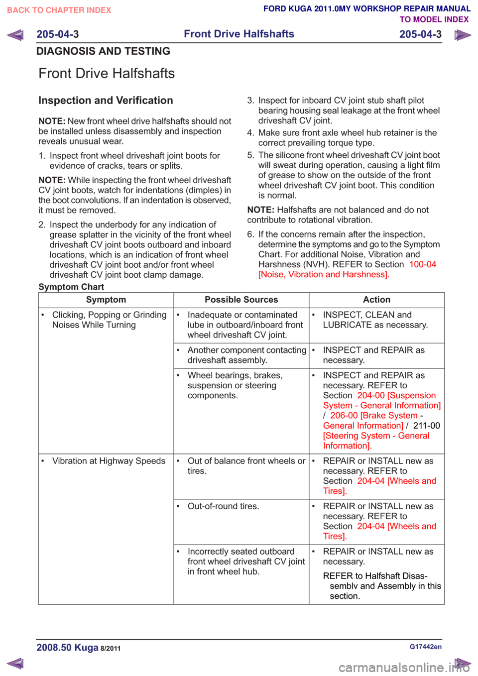
Front Drive Halfshafts
Inspection and Verification
NOTE:New front wheel drive halfshafts should not
be installed unless disassembly and inspection
reveals unusual wear.
1. Inspect front wheel driveshaft joint boots for evidence of cracks, tears or splits.
NOTE: While inspecting the front wheel driveshaft
CV joint boots, watch for indentations (dimples) in
the boot convolutions. If an indentation is observed,
it must be removed.
2. Inspect the underbody for any indication of grease splatter in the vicinity of the front wheel
driveshaft CV joint boots outboard and inboard
locations, which is an indication of front wheel
driveshaft CV joint boot and/or front wheel
driveshaft CV joint boot clamp damage. 3. Inspect for inboard CV joint stub shaft pilot
bearing housing seal leakage at the front wheel
driveshaft CV joint.
4. Make sure front axle wheel hub retainer is the correct prevailing torque type.
5. The silicone front wheel driveshaft CV joint boot will sweat during operation, causing a light film
of grease to show on the outside of the front
wheel driveshaft CV joint boot. This condition
is normal.
NOTE: Halfshafts are not balanced and do not
contribute to rotational vibration.
6. If the concerns remain after the inspection, determine the symptoms and go to the Symptom
Chart. For additional Noise, Vibration and
Harshness (NVH). REFER to Section 100-04
[Noise, Vibration and Harshness] .
Symptom Chart
Action
Possible Sources
Symptom
• INSPECT, CLEAN andLUBRICATE as necessary.
• Inadequate or contaminated
lube in outboard/inboard front
wheel driveshaft CV joint.
• Clicking, Popping or Grinding
Noises While Turning
• INSPECT and REPAIR asnecessary.
• Another component contacting
driveshaft assembly.
• INSPECT and REPAIR asnecessary. REFER to
Section 204-00 [Suspension
System - General Information]
/ 206-00 [Brake System -
General Information] /211-00
[Steering System - General
Information] .
• Wheel bearings, brakes,
suspension or steering
components.
• REPAIR or INSTALL new asnecessary. REFER to
Section 204-04 [Wheels and
Tires] .
• Out of balance front wheels or
tires.
• Vibration at Highway Speeds
• REPAIR or INSTALL new asnecessary. REFER to
Section 204-04 [Wheels and
Tires] .
• Out-of-round tires.
• REPAIR or INSTALL new asnecessary.
REFER to Halfshaft Disas-
semblv and Assembly in this
section.
• Incorrectly seated outboard
front wheel driveshaft CV joint
in front wheel hub.
G17442en2008.50 Kuga8/2011
205-04- 3
Front Drive Halfshafts
205-04- 3
DIAGNOSIS AND TESTING
TO MODEL INDEX
BACK TO CHAPTER INDEX
FORD KUGA 2011.0MY WORKSHOP REPAIR MANUAL
Page 1447 of 2057
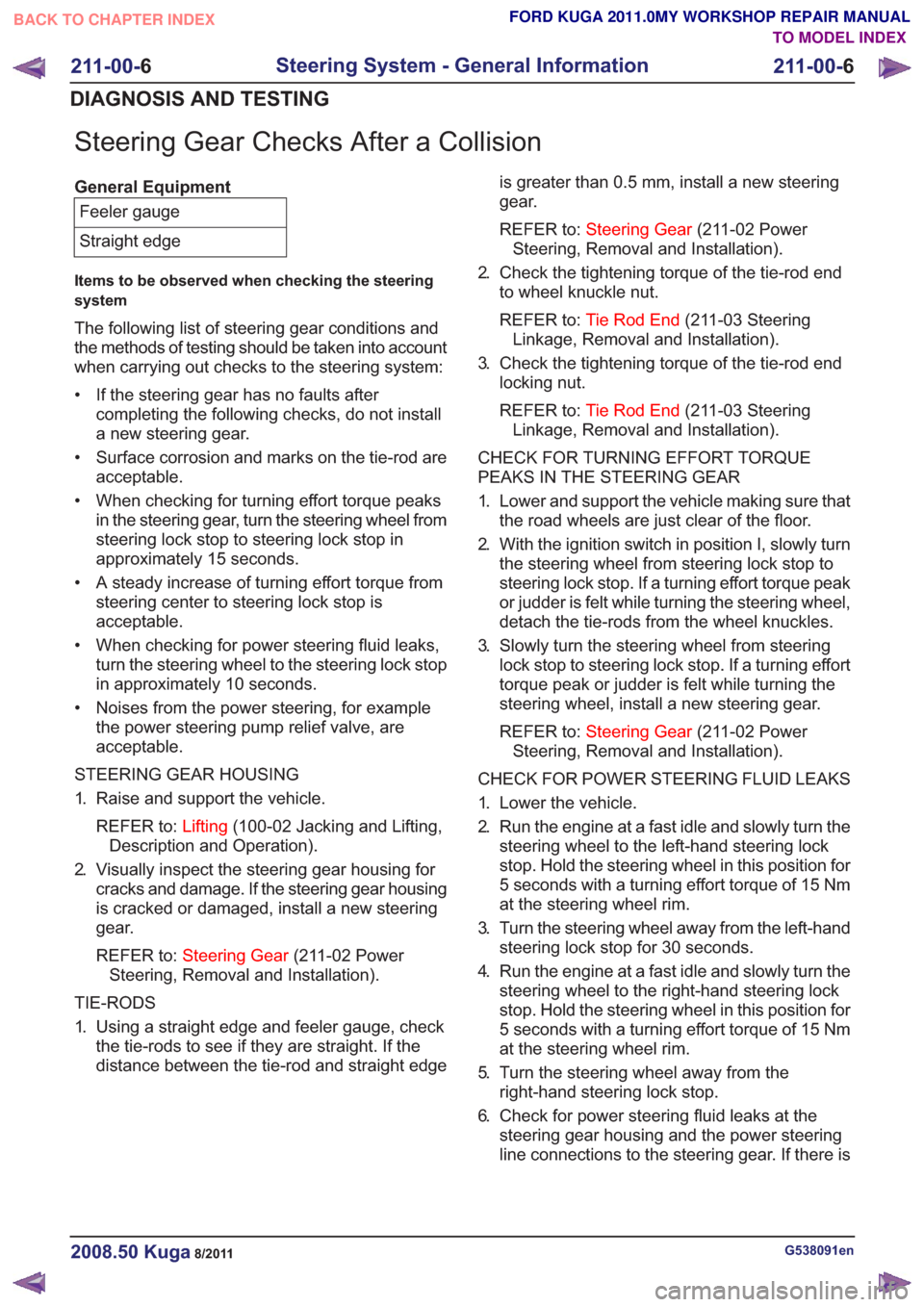
Steering Gear Checks After a Collision
General EquipmentFeeler gauge
Straight edge
Items to be observed when checking the steering
system
The following list of steering gear conditions and
the methods of testing should be taken into account
when carrying out checks to the steering system:
• If the steering gear has no faults after completing the following checks, do not install
a new steering gear.
• Surface corrosion and marks on the tie-rod are acceptable.
• When checking for turning effort torque peaks in the steering gear, turn the steering wheel from
steering lock stop to steering lock stop in
approximately 15 seconds.
• A steady increase of turning effort torque from steering center to steering lock stop is
acceptable.
• When checking for power steering fluid leaks, turn the steering wheel to the steering lock stop
in approximately 10 seconds.
• Noises from the power steering, for example the power steering pump relief valve, are
acceptable.
STEERING GEAR HOUSING
1. Raise and support the vehicle. REFER to: Lifting(100-02 Jacking and Lifting,
Description and Operation).
2. Visually inspect the steering gear housing for cracks and damage. If the steering gear housing
is cracked or damaged, install a new steering
gear.
REFER to: Steering Gear (211-02 Power
Steering, Removal and Installation).
TIE-RODS
1. Using a straight edge and feeler gauge, check the tie-rods to see if they are straight. If the
distance between the tie-rod and straight edge is greater than 0.5 mm, install a new steering
gear.
REFER to:
Steering Gear (211-02 Power
Steering, Removal and Installation).
2. Check the tightening torque of the tie-rod end to wheel knuckle nut.
REFER to: Tie Rod End (211-03 Steering
Linkage, Removal and Installation).
3. Check the tightening torque of the tie-rod end locking nut.
REFER to: Tie Rod End (211-03 Steering
Linkage, Removal and Installation).
CHECK FOR TURNING EFFORT TORQUE
PEAKS IN THE STEERING GEAR
1. Lower and support the vehicle making sure that the road wheels are just clear of the floor.
2. With the ignition switch in position I, slowly turn the steering wheel from steering lock stop to
steering lock stop. If a turning effort torque peak
or judder is felt while turning the steering wheel,
detach the tie-rods from the wheel knuckles.
3. Slowly turn the steering wheel from steering lock stop to steering lock stop. If a turning effort
torque peak or judder is felt while turning the
steering wheel, install a new steering gear.
REFER to: Steering Gear (211-02 Power
Steering, Removal and Installation).
CHECK FOR POWER STEERING FLUID LEAKS
1. Lower the vehicle.
2. Run the engine at a fast idle and slowly turn the steering wheel to the left-hand steering lock
stop. Hold the steering wheel in this position for
5 seconds with a turning effort torque of 15 Nm
at the steering wheel rim.
3. Turn the steering wheel away from the left-hand steering lock stop for 30 seconds.
4. Run the engine at a fast idle and slowly turn the steering wheel to the right-hand steering lock
stop. Hold the steering wheel in this position for
5 seconds with a turning effort torque of 15 Nm
at the steering wheel rim.
5. Turn the steering wheel away from the right-hand steering lock stop.
6. Check for power steering fluid leaks at the steering gear housing and the power steering
line connections to the steering gear. If there is
G538091en2008.50 Kuga8/2011
211-00- 6
Steering System - General Information
211-00- 6
DIAGNOSIS AND TESTING
TO MODEL INDEX
BACK TO CHAPTER INDEX
FORD KUGA 2011.0MY WORKSHOP REPAIR MANUAL
Page 1460 of 2057
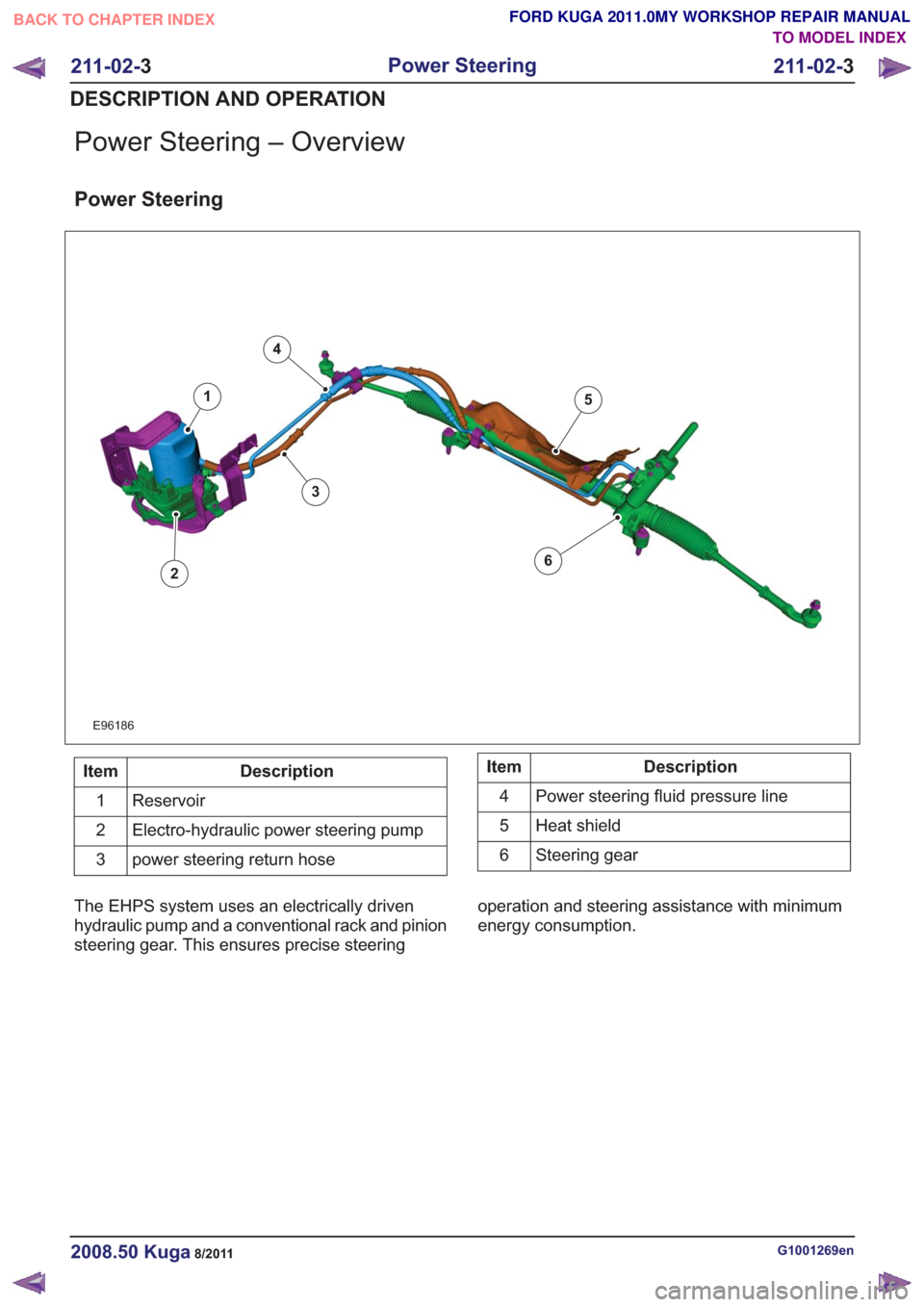
Power Steering – Overview
Power Steering
E96186
1
2
3
4
5
6
Description
Item
Reservoir
1
Electro-hydraulic power steering pump
2
power steering return hose
3Description
Item
Power steering fluid pressure line
4
Heat shield
5
Steering gear
6
The EHPS system uses an electrically driven
hydraulic pump and a conventional rack and pinion
steering gear. This ensures precise steering operation and steering assistance with minimum
energy consumption.
G1001269en2008.50 Kuga8/2011
211-02-
3
Power Steering
211-02- 3
DESCRIPTION AND OPERATION
TO MODEL INDEX
BACK TO CHAPTER INDEX
FORD KUGA 2011.0MY WORKSHOP REPAIR MANUAL
Page 1462 of 2057
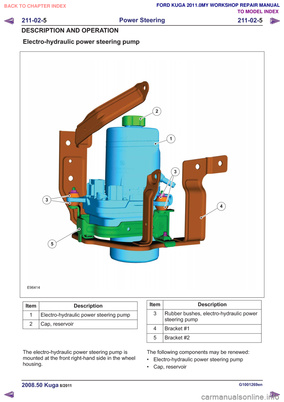
Electro-hydraulic power steering pump
E96414
1
2
3
4
5
3
Description
Item
Electro-hydraulic power steering pump
1
Cap, reservoir
2Description
Item
Rubber bushes, electro-hydraulic power
steering pump
3
Bracket #1
4
Bracket #2
5
The electro-hydraulic power steering pump is
mounted at the front right-hand side in the wheel
housing. The following components may be renewed:
• Electro-hydraulic power steering pump
• Cap, reservoir
G1001269en2008.50 Kuga8/2011
211-02-
5
Power Steering
211-02- 5
DESCRIPTION AND OPERATION
TO MODEL INDEX
BACK TO CHAPTER INDEX
FORD KUGA 2011.0MY WORKSHOP REPAIR MANUAL
Page 1463 of 2057
• Rubber bushes, electro-hydraulic power steeringpump
• Bracket #1
• Bracket #2
During removal and installation or renewal of
components of the electro-hydraulic power steering
pump, pay attention to the following:
• Before starting work to renew the electro-hydraulic power steering pump, the
program code of the electro-hydraulic power steering must be read out using the diagnostic
unit and noted.
• After the work to renew the electro-hydraulic power steering pump is completed, the
electro-hydraulic power steering must be
reconfigured using the diagnostic unit. For
further information, see: Module Configuration
(418-01 Module Configuration, General
Procedures).
• The electro-hydraulic power steering pump must be filled and vented as specified.
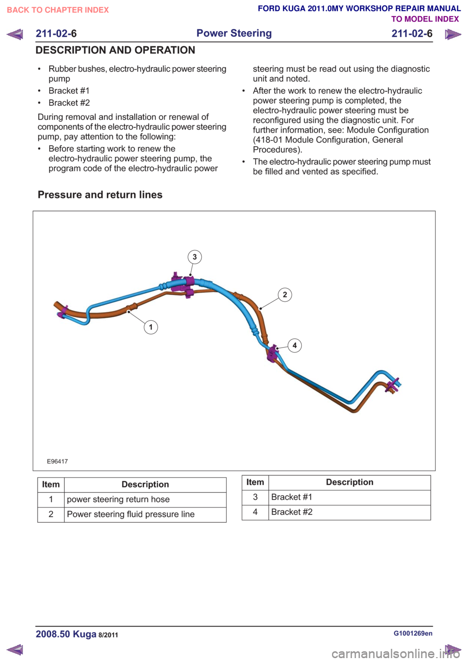
Pressure and return lines
E96417
1
2
3
4
Description
Item
power steering return hose
1
Power steering fluid pressure line
2Description
Item
Bracket #1
3
Bracket #2
4
G1001269en2008.50 Kuga8/2011
211-02- 6
Power Steering
211-02- 6
DESCRIPTION AND OPERATION
TO MODEL INDEX
BACK TO CHAPTER INDEX
FORD KUGA 2011.0MY WORKSHOP REPAIR MANUAL
Page 1466 of 2057
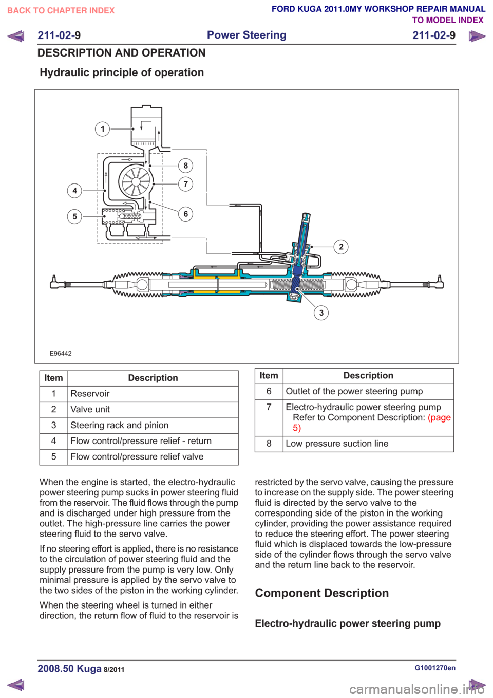
Hydraulic principle of operation
E96442
3
4
5
7
8
6
1
2
Description
Item
Reservoir
1
Valve unit
2
Steering rack and pinion
3
Flow control/pressure relief - return
4
Flow control/pressure relief valve
5Description
Item
Outlet of the power steering pump
6
Electro-hydraulic power steering pumpRefertoComponentDescription:(page
5)
7
Low pressure suction line
8
When the engine is started, the electro-hydraulic
power steering pump sucks in power steering fluid
from the reservoir. The fluid flows through the pump
and is discharged under high pressure from the
outlet. The high-pressure line carries the power
steering fluid to the servo valve.
If no steering effort is applied, there is no resistance
to the circulation of power steering fluid and the
supply pressure from the pump is very low. Only
minimal pressure is applied by the servo valve to
the two sides of the piston in the working cylinder.
When the steering wheel is turned in either
direction, the return flow of fluid to the reservoir is restricted by the servo valve, causing the pressure
to increase on the supply side. The power steering
fluid is directed by the servo valve to the
corresponding side of the piston in the working
cylinder, providing the power assistance required
to reduce the steering effort. The power steering
fluid which is displaced towards the low-pressure
side of the cylinder flows through the servo valve
and the return line back to the reservoir.
Component Description
Electro-hydraulic power steering pump
G1001270en2008.50 Kuga8/2011
211-02-
9
Power Steering
211-02- 9
DESCRIPTION AND OPERATION
TO MODEL INDEX
BACK TO CHAPTER INDEX
FORD KUGA 2011.0MY WORKSHOP REPAIR MANUAL
Page 1511 of 2057

Steering Column Switches – Overview
Switch unit, steering column
E98629
1
2
3
4
5
Description
Item
Left-hand switch, steering column
1
Switch unit carrier, steering column
2
Right-hand switch, steering column
3Description
Item
Steering wheel rotation sensor
Refer to: Anti-Lock Control - Stability
Assist (206-09 Anti-Lock Control -
Stability Assist, Description and
Operation).
4
Clockspring
5
Clockspring
The clockspring is designed to carry signals
between the RCM and the driver air bag module.
The clockspring is installed on the steering column,
and consists of fixed and moving parts connected
by a coiled Mylar tape with internal conducting
tracks. The Mylar tape is able to 'wind up' and
'unwind' as the steering wheel is rotated,
maintaining electrical contact at all times between
the RCM and the driver air bag module. During removal and installation or renewal of the
clockspring, pay attention to the following:
• Before installation of the clockspring, it must be
aligned according to the installation instructions.
• Make sure that the vehicle electrical system is fully depowered and no other power source is
connected.
• Secure the clockspring rotor with adhesive tape to the clockspring outer.
• The clockspring rotor must not be turned during removal or installation of the steering wheel or
the steering column switch unit.
G1030755en2008.50 Kuga8/2011
211-05- 3
Steering Column Switches
211-05- 3
DESCRIPTION AND OPERATION
TO MODEL INDEX
BACK TO CHAPTER INDEX
FORD KUGA 2011.0MY WORKSHOP REPAIR MANUAL