2011 FORD KUGA smart charge system
[x] Cancel search: smart charge systemPage 273 of 2057

SECTION 414-02 Generator and Regulator
VEHICLE APPLICATION:
2008.50 Kuga
PAGE
CONTENTS
DESCRIPTION AND OPERATION
414-02-2
Generator ............................................................................................................................
414-02-2
Smart Charge system.........................................................................................................
REMOVAL AND INSTALLATION 414-02-3
(31 414 0)
Generator — 2.5L Duratec (147kW/200PS) - VI5.......................................... 414-02-1
Generator and Regulator
414-02-1
.TO MODEL INDEX
BACK TO CHAPTER INDEX
FORD KUGA 2011.0MY WORKSHOP REPAIR MANUAL
Page 274 of 2057

Generator
General information
The powertrain control module (PCM) controls the
alternator charging voltage. The connection
between the PCM and the generator is made via
the control module subnetwork (LIN) bus.
If the load on the alternator is high, the PCM can
increase the idle speed.
The alternator is temporarily deactivated during
engine starting so that the engine drag moment is
minimized and it is reactivated again after the
starting procedure.
The PCM controls the charge control lamp in the
instrument cluster via the controller area network
(CAN) bus.
Smart Charge system
In addition to the familiar functions, the Smart
Charge system also performs the following
functions:
•
Automatic deactivation of non-critical high power
electrical consumers when the battery voltage
is low in order to reduce the level of current
drawn.
• Automatic activation of non-critical high power electrical consumers when the battery voltage
is excessively high in order to protect
components which are sensitive to increased
voltages.
The battery charging current is optimized through
continuous calculation of the battery temperature
and monitoring of the alternator output voltage.
By receiving the forwarded alternator load signal,
the PCM is given early warning whenever an
electric consumer is switched on or off. This means
that the PCM receives information about imminent
changes in the torque drawn by the alternator. By
evaluating this information the PCM can provide a
higher level of idling stability.
The two remaining functions of the Smart Charge
System are controlled by the GEM.
Electrical consumers are switched off due to low
voltage when the GEM determines (on the basis
of the message received from the PCM on the CAN
bus via the instrument cluster) that the battery
voltage has dropped below the threshold.
When the threshold for low battery voltage is
reached the GEM automatically deactivates the following consumers - in this order and with a gap
of 5 seconds between each:
• Electric booster heater (vehicles with diesel
engines)
• Heated exterior mirrors
• Heated rear window
• Heated windscreen
If the battery voltage rises back above the lower
threshold then the GEM re-enables all of the
electrical consumers which were previously
disabled. They then have switched off status and
must be switched back on by the driver.
Electrical consumers are switched on due to
excessively high voltage if the GEM determines
that the battery voltage is above the threshold for
overvoltage and the charge control lamp has been
switched on.
When the threshold is reached the GEM
automatically activates the following consumers -
in this order and with a gap of 5 seconds between
each:
• Heated rear window
• Heated exterior mirrors
• Electric booster heater (vehicles with diesel engines)
• Blower motor
If the battery voltage drops back below the
threshold then the GEM automatically deactivates
any consumers that were switched on. However,
if they were switched on by the driver before the
automatic activation, they will then be switched on
again in turn with a 5-second time interval. G964174en
2008.50 Kuga 8/2011 414-02-2
Generator and Regulator
414-02-2
DESCRIPTION AND OPERATIONTO MODEL INDEX
BACK TO CHAPTER INDEX
FORD KUGA 2011.0MY WORKSHOP REPAIR MANUAL
Page 451 of 2057

SECTION 419-10 Multifunction Electronic Modules
VEHICLE APPLICATION:
2008.50 Kuga
PAGE
CONTENTS
DESCRIPTION AND OPERATION
419-10-2
Module Controlled Functions (Overview)...........................................................................
419-10-2
Generic electronics module (GEM)....................................................................................
419-10-2
Emergency function............................................................................................................
419-10-2
Service mode......................................................................................................................
419-10-4
Module Controlled Functions (System Operation and Component Description)................
419-10-4
System Diagram.................................................................................................................
419-10-6
System Operation...............................................................................................................
419-10-6
GEM. ...............................................................................................................................
419-10-6
Component Description......................................................................................................
419-10-6
Battery charging (Smart Charge)....................................................................................
419-10-7
Ignition overload protection.............................................................................................
419-10-7
Headlamp switch-off delay..............................................................................................
419-10-8
Turn signals....................................................................................................................
419-10-8
Interior lighting................................................................................................................
419-10-8
Heated windscreen.........................................................................................................
419-10-9
Heated rear window and heated external mirrors...........................................................
419-10-9
Ambient air temperature.................................................................................................
419-10-9
Brake fluid level...............................................................................................................
419-10-9
Automatic headlamps.....................................................................................................
419-10-9
Combined rain sensor/light sensor.................................................................................419-10-10Windshield wash/wipe system........................................................................................
419-10-10Anti-theft ..........................................................................................................................
419-10-10Electric booster Heater...................................................................................................
419-10-10Climate control................................................................................................................
DIAGNOSIS AND TESTING 419-10-11
Generic Electronic Module (GEM)......................................................................................
419-10-11
Description of operation......................................................................................................
419-10-12
Inspection and Checking....................................................................................................
REMOVAL AND INSTALLATION 419-10-14
Generic Electronic Module (GEM)......................................................................................
419-10-15
Lighting Control Module (LCM)........................................................................................... 419-10-1
Multifunction Electronic Modules
419-10-1
.
TO MODEL INDEX
BACK TO CHAPTER INDEX
FORD KUGA 2011.0MY WORKSHOP REPAIR MANUAL
Page 456 of 2057

Description
Item
HS CAN
1
DLC2
MS CAN
3
Instrument cluster (gateway)
4
Front windshield wiper motors
5
GEM6
Rear window wiper motors
7
Indicator/heated windshield
8
Indicator/heated rear window
9 Description
Item
Mini-liftgate latch motor
10
Liftgate latch motor
11
Electric booster Heater
12
Front wiper windscreen washer pump
13
Rear wiper windscreen washer pump
14
Headlamp
15
Courtesy Lighting
16
Alarm horn
17
System Operation
GEM.
The following functions are controlled or performed
by the GEM at a battery voltage of between 9 and
16 volts:
• Current distribution
• Battery charging (Smart Charge)
• Ignition overload protection
• Headlamp switch-off delay
• Turn signals
• Interior lighting
• Heated windscreen
• Heated rear window and heated external mirrors
• Ambient air temperature
• Brake fluid level
• Automatic headlamps
• Combined rain sensor/light sensor
• Windshield wash/wipe system
• Speed control – reads the speed control switches andtransmits signals on the CAN data bus
• central door locking – transmits signals on the CAN data bus
• Anti-theft
• Electric booster Heater
• Climate control
• Parking brake –(monitors the switch and transmits the signal
on the CAN data bus
• Communication via the medium-speed CAN data bus Component Description
Battery charging (Smart Charge)
In addition to the familiar functions, the Smart
Charge system also performs the following
functions:
•
Automatic deactivation of non-critical high power
electrical consumers when the battery voltage
is low in order to reduce the level of current
drawn.
• Automatic activation of non-critical high power electrical consumers when the battery voltage
is excessively high in order to protect
components which are sensitive to increased
voltages.
The battery charging current is optimized through
continuous calculation of the battery temperature
and monitoring of the alternator output voltage.
The alternator load is signaled to the PCM
(powertrain control module) in order to provide it
with an early indication when an electric component
is to be switched on or off, thereby also providing
information about imminent changes to the amount
of torque demanded by the alternator. By
evaluating this information the PCM is capable of
increasing the stability of the engine under idling.
The two remaining functions of the Smart Charge
system are controlled by the GEM. G1030788en
2008.50 Kuga 8/2011 419-10-6
Multifunction Electronic Modules
419-10-6
DESCRIPTION AND OPERATIONTO MODEL INDEX
BACK TO CHAPTER INDEX
FORD KUGA 2011.0MY WORKSHOP REPAIR MANUAL
Page 1775 of 2057

SECTION 303-14 Electronic Engine Controls— 2.5L Duratec
(147kW/200PS) - VI5
VEHICLE APPLICATION: 2008.50 Kuga
PA G E
CONTENTS
DESCRIPTION AND OPERATION
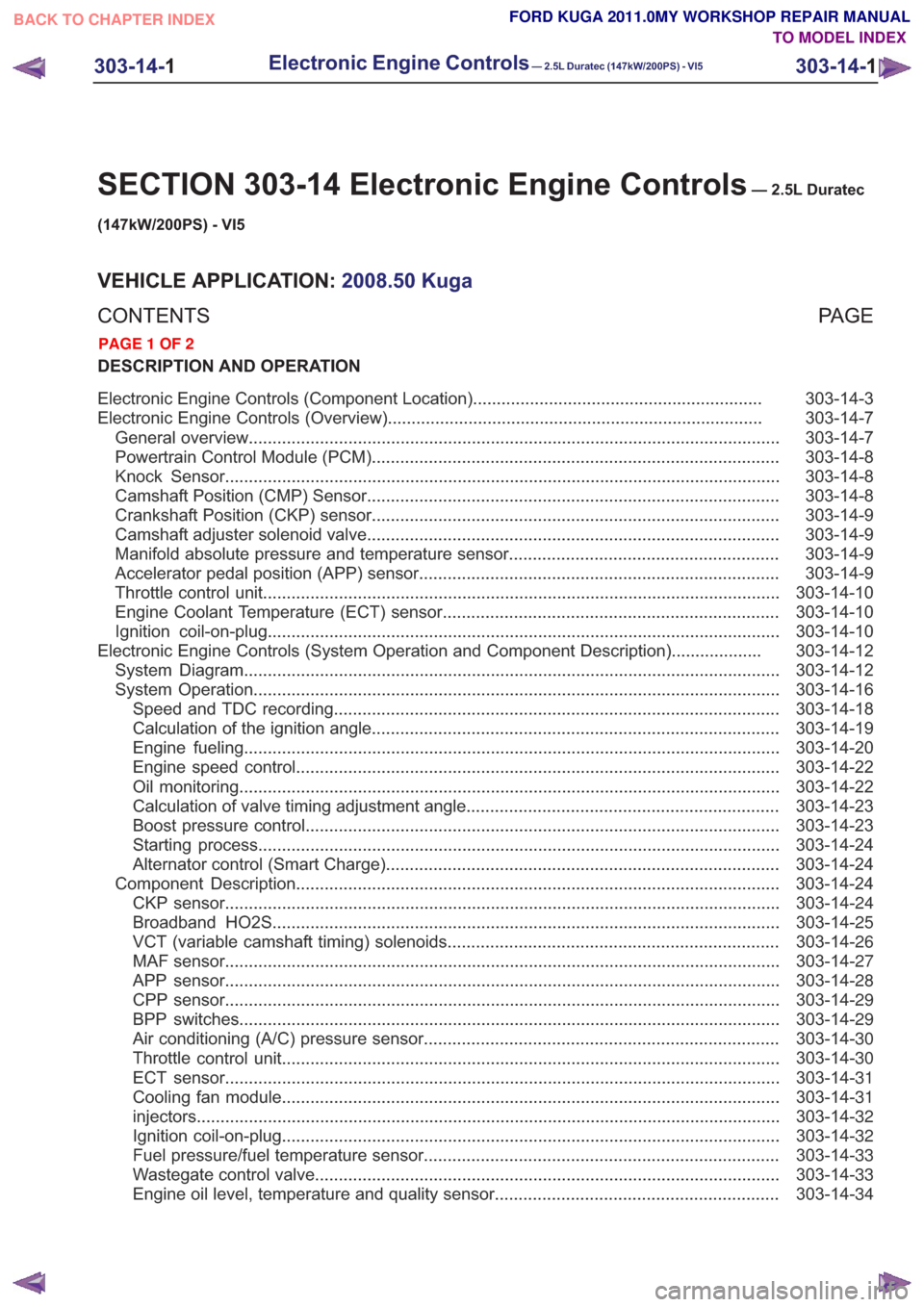
303-14-3
Electronic Engine Controls (Component Location) .............................................................
303-14-7
Electronic Engine Controls (Overview) ........................................................................\
.......
303-14-7
General overview ........................................................................\
........................................
303-14-8
Powertrain Control Module (PCM) ........................................................................\
..............
303-14-8
Knock Sensor ........................................................................\
.............................................
303-14-8
Camshaft Position (CMP) Sensor ........................................................................\
...............
303-14-9
Crankshaft Position (CKP) sensor ........................................................................\
..............
303-14-9
Camshaft adjuster solenoid valve........................................................................\
...............
303-14-9
Manifold absolute pressure and temperature sensor .........................................................
303-14-9
Accelerator pedal position (APP) sensor ........................................................................\
....
303-14-10
Throttle control unit ........................................................................\
.....................................
303-14-10
Engine Coolant Temperature (ECT) sensor.......................................................................
303-14-10
Ignition coil-on-plug ........................................................................\
....................................
303-14-12
Electronic Engine Controls (System Operation and Component Description) ...................
303-14-12
System Diagram ........................................................................\
.........................................
303-14-16
System Operation ........................................................................\
.......................................
303-14-18
Speed and TDC recording ........................................................................\
......................
303-14-19
Calculation of the ignition angle ........................................................................\
..............
303-14-20
Engine fueling ........................................................................\
.........................................
303-14-22
Engine speed control ........................................................................\
..............................
303-14-22
Oil monitoring ........................................................................\
..........................................
303-14-23
Calculation of valve timing adjustment angle..................................................................
303-14-23
Boost pressure control ........................................................................\
............................
303-14-24
Starting process ........................................................................\
......................................
303-14-24
Alternator control (Smart Charge) ........................................................................\
...........
303-14-24
Component Description ........................................................................\
..............................
303-14-24
CKP sensor ........................................................................\
.............................................
303-14-25
Broadband HO2S ........................................................................\
...................................
303-14-26
VCT (variable camshaft timing) solenoids ......................................................................
303-14-27
MAF sensor ........................................................................\
.............................................
303-14-28
APP sensor ........................................................................\
.............................................
303-14-29
CPP sensor ........................................................................\
.............................................
303-14-29
BPP switches ........................................................................\
..........................................
303-14-30
Air conditioning (A/C) pressure sensor ........................................................................\
...
303-14-30
Throttle
control unit ........................................................................\
.................................
303-14-31
ECT sensor ........................................................................\
.............................................
303-14-31
Cooling fan module ........................................................................\
.................................
303-14-32
injectors........................................................................\
...................................................
303-14-32
Ignition coil-on-plug ........................................................................\
.................................
303-14-33
Fuel pressure/fuel temperature sensor ........................................................................\
...
303-14-33
Wastegate control valve ........................................................................\
..........................
303-14-34
Engine oil level, temperature and quality sensor ............................................................
303-14-1
Electronic Engine Controls— 2.5L Duratec (147kW/200PS) - VI5303-14-
1
.
TO MODEL INDEX
BACK TO CHAPTER INDEX
PAGE 1 OF 2
FORD KUGA 2011.0MY WORKSHOP REPAIR MANUAL
Page 1782 of 2057

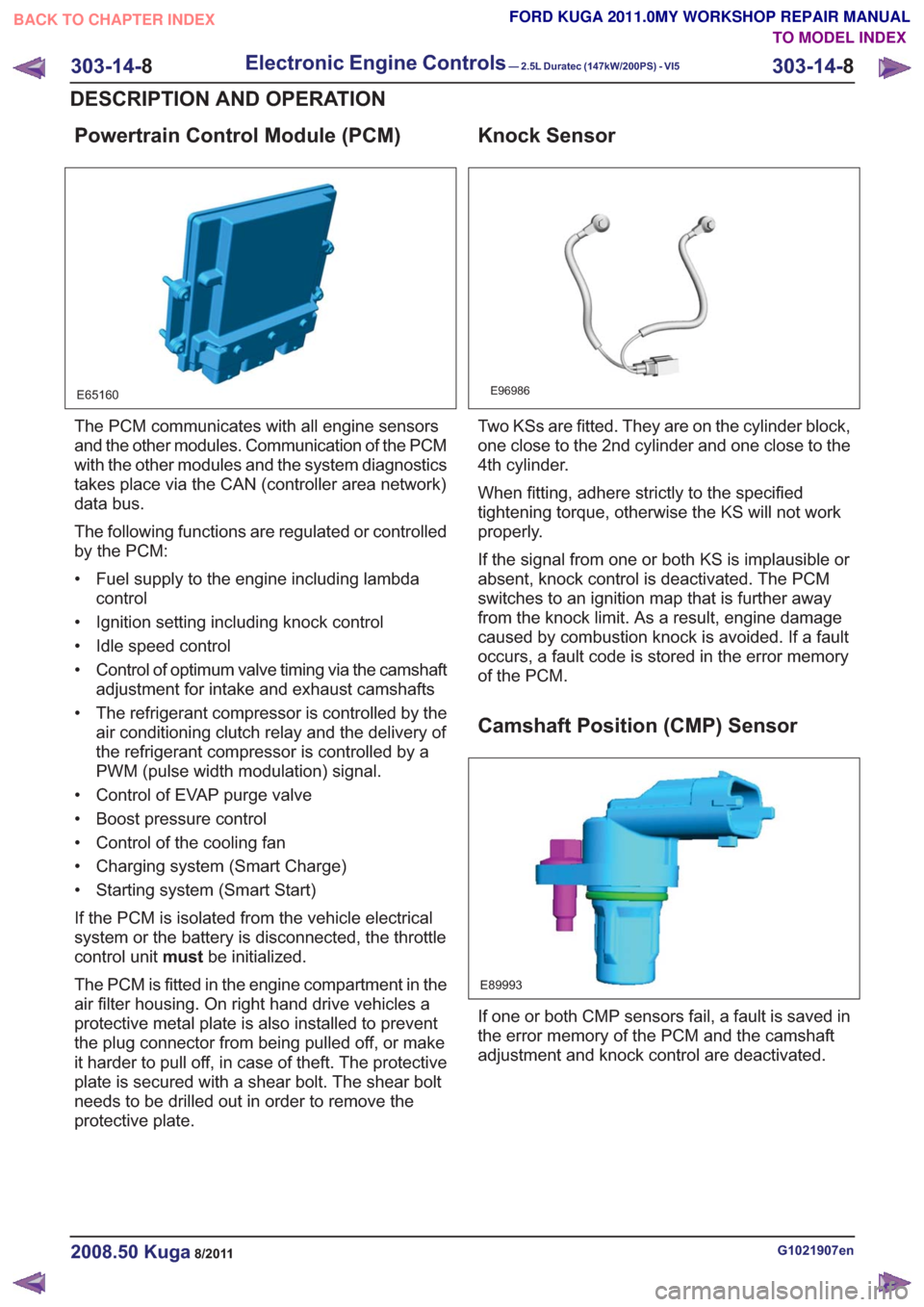
Powertrain Control Module (PCM)
E65160
The PCM communicates with all engine sensors
and the other modules. Communication of the PCM
with the other modules and the system diagnostics
takes place via the CAN (controller area network)
data bus.
The following functions are regulated or controlled
by the PCM:
• Fuel supply to the engine including lambdacontrol
• Ignition setting including knock control
• Idle speed control
• Control of optimum valve timing via the camshaft adjustment for intake and exhaust camshafts
• The refrigerant compressor is controlled by the air conditioning clutch relay and the delivery of
the refrigerant compressor is controlled by a
PWM (pulse width modulation) signal.
• Control of EVAP purge valve
• Boost pressure control
• Control of the cooling fan
• Charging system (Smart Charge)
• Starting system (Smart Start)
If the PCM is isolated from the vehicle electrical
system or the battery is disconnected, the throttle
control unit mustbe initialized.
The PCM is fitted in the engine compartment in the
air filter housing. On right hand drive vehicles a
protective metal plate is also installed to prevent
the plug connector from being pulled off, or make
it harder to pull off, in case of theft. The protective
plate is secured with a shear bolt. The shear bolt
needs to be drilled out in order to remove the
protective plate.
Knock Sensor
E96986
Two KSs are fitted. They are on the cylinder block,
one close to the 2nd cylinder and one close to the
4th cylinder.
When fitting, adhere strictly to the specified
tightening torque, otherwise the KS will not work
properly.
If the signal from one or both KS is implausible or
absent, knock control is deactivated. The PCM
switches to an ignition map that is further away
from the knock limit. As a result, engine damage
caused by combustion knock is avoided. If a fault
occurs, a fault code is stored in the error memory
of the PCM.
Camshaft Position (CMP) Sensor
E89993
If one or both CMP sensors fail, a fault is saved in
the error memory of the PCM and the camshaft
adjustment and knock control are deactivated.
G1021907en2008.50 Kuga8/2011
303-14- 8
Electronic Engine Controls— 2.5L Duratec (147kW/200PS) - VI5303-14-
8
DESCRIPTION AND OPERATION
TO MODEL INDEX
BACK TO CHAPTER INDEX
FORD KUGA 2011.0MY WORKSHOP REPAIR MANUAL
Page 1798 of 2057

Starting process
The PCM enables the starting process when a key
providing a valid code is read via the PATS.
Refer to:Starting System (303-06 Starting System
- 2.5L Duratec (147kW/200PS) - VI5, Description
and Operation).
Alternator control (Smart Charge)
The vehicle is fitted with a Smart Charging charge
system.
In this system, the charge voltage is regulated by
the PCM.
Refer to: Generator (414-02 Generator and
Regulator, Description and Operation).
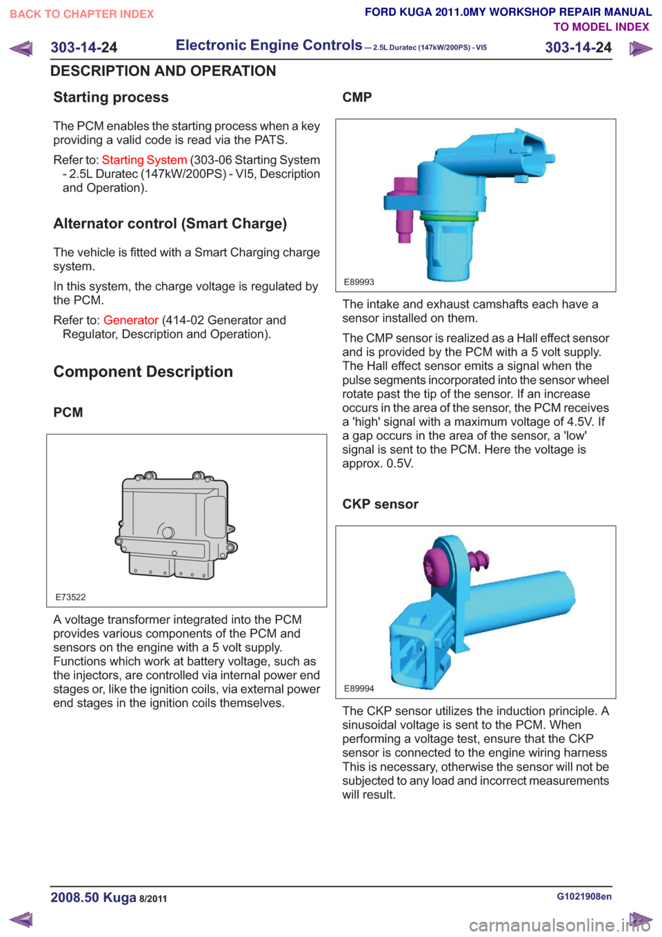
Component Description
PCM
E73522
A voltage transformer integrated into the PCM
provides various components of the PCM and
sensors on the engine with a 5 volt supply.
Functions which work at battery voltage, such as
the injectors, are controlled via internal power end
stages or, like the ignition coils, via external power
end stages in the ignition coils themselves.
CMP
E89993
The intake and exhaust camshafts each have a
sensor installed on them.
The CMP sensor is realized as a Hall effect sensor
and is provided by the PCM with a 5 volt supply.
The Hall effect sensor emits a signal when the
pulse segments incorporated into the sensor wheel
rotate past the tip of the sensor. If an increase
occurs in the area of the sensor, the PCM receives
a 'high' signal with a maximum voltage of 4.5V. If
a gap occurs in the area of the sensor, a 'low'
signal is sent to the PCM. Here the voltage is
approx. 0.5V.
CKP sensor
E89994
The CKP sensor utilizes the induction principle. A
sinusoidal voltage is sent to the PCM. When
performing a voltage test, ensure that the CKP
sensor is connected to the engine wiring harness
This is necessary, otherwise the sensor will not be
subjected to any load and incorrect measurements
will result.
G1021908en2008.50 Kuga8/2011
303-14- 24
Electronic Engine Controls— 2.5L Duratec (147kW/200PS) - VI5303-14-
24
DESCRIPTION AND OPERATION
TO MODEL INDEX
BACK TO CHAPTER INDEX
FORD KUGA 2011.0MY WORKSHOP REPAIR MANUAL