2011 FORD KUGA brake vacuum
[x] Cancel search: brake vacuumPage 51 of 2057
The use of drum cleaning units, vacuum cleaning
or damp wiping is preferred.
Asbestos dust waste should be dampened, placed
in a sealed container and marked for safe disposal.
If any cutting or drilling is attempted on materials
containing asbestos the item should be dampened
and only hand tools or low speed power tools used.
Battery Acids
See also Acids and Alkalis.
For additional information, refer to:Battery and
Battery Charging Health and Safety Precautions
(100-00 General Information, Description and
Operation).
Brake and Clutch Linings and Pads
See Asbestos.
Brake Fluids (Polyalkylene Glycols)
See also Fire.
For additional information, refer to: Brake System
Health and Safety Precautions (100-00 General
Information, Description and Operation).
Brazing
See Welding.
Chemical Materials
See also Legal Aspects.
Chemical materials such as solvents, sealers,
adhesives, paints, resin foams, battery acids,
antifreeze, brake fluids, fuels, oils and grease
should always be used with caution and stored and
handled with care. They may be toxic, harmful,
corrosive, irritant or highly flammable and give rise
to hazardous fumes and dusts.
The effects of excessive exposure to chemicals
may be immediate or delayed; briefly experienced
or permanent; cumulative; superficial; life
threatening; or may reduce life expectancy.
Chemical Materials - Do's
– Do carefully read and observe hazard and precaution warnings given on material
containers (labels) and in any accompanying
leaflets, posters or other instructions. Material
health and safety data sheets can be obtained
from manufacturers.
– Do remove chemical materials from the skin and clothing as soon as practicable after soiling.
Change heavily soiled clothing and have it
cleaned.
– Do organize work practices and protective clothing to avoid soiling of the skin and eyes;
breathing vapors, aerosols, dusts or fumes;
inadequate container labeling; fire and explosion
hazards.
– Do wash before job breaks, before eating, smoking, drinking or using toilet facilities when
handling chemical materials.
– Do keep work areas clean, uncluttered and free of spills.
– Do store chemical materials according to national and local regulations.
– Do keep chemical materials out of the reach of children.
Chemical Materials - Do Nots
– Do not mix chemical materials except under themanufacturers instructions; some chemicals can
form other toxic or harmful chemicals, give off
toxic or harmful fumes or become explosive
when mixed together.
– Do not spray chemical materials, particularly those based on solvents, in confined spaces,
for example when people are inside a vehicle.
– Do not apply heat or flame to chemical materials except under the manufacturers instructions.
Some are highly flammable and some may
release toxic or harmful fumes.
– Do not leave containers open. Fumes given off can build up to toxic, harmful or explosive
concentrations. Some fumes are heavier than
air and will accumulate in confined areas such
as pits.
– Do not transfer chemical materials to unlabelled containers.
– Do not clean hands or clothing with chemicals. Chemicals, particularly solvents and fuels, will
dry the skin and may cause irritation leading to
G566527en2008.50 Kuga8/2011
100-00- 44
General Information
100-00- 44
DESCRIPTION AND OPERATION
TO MODEL INDEX
BACK TO CHAPTER INDEX
FORD KUGA 2011.0MY WORKSHOP REPAIR MANUAL
Page 62 of 2057

TIM0103001
WARNING: Make sure that the ends of the
jumper cables do not touch each other or
ground against the vehicle body at any
time while the cables are attached to the
battery. A fully charged battery, if shorted
through jumper cables, can discharge at
a rate well above 1000 amps causing
violent arcing and very rapid heating of the
jumper cables and terminals, and can even
cause the battery to explode. Failure to
follow these instructions may result in
personal injury.
Always connect the jumper cables in the following
sequence:
– Slave battery positive first and then vehicle battery positive.
– Slave battery negative next and then vehicle ground at least 12 inches (300 mm) from the
battery terminal, for example engine lifting eye.
Always reduce the engine speed to idle before
disconnecting the jumper cables.
Before removing the jumper cables from the vehicle
that had the discharged battery, switch on the
heater blower (high) or the heated rear window, to
reduce the voltage peak when the cables are
removed.
Always disconnect the jumper cables in the reverse
order to the connecting sequence and do not short
the ends of the cables.
Do not rely on the generator to restore a
discharged battery. For a generator to recharge a
battery, it would take in excess of eight hours
continuous driving with no additional loads placed
on the battery.
Component Cleaning
To prevent the ingress of dirt, accumulations of
loose dirt and greasy deposits should be removed before disconnecting or dismantling components
or assemblies.
Components should be thoroughly cleaned before
inspection prior to reassembly.
Cleaning Methods:
– Dry cleaning.
– Removal of loose dirt with soft or cable brushes.
– Scraping dirt off with a piece of metal or wood.
– Wiping off with a rag.
WARNING: Wear eye protection when
cleaning vehicle components with
compressed air, a steam cleaner or a
power washer. Failure to follow this
instruction may result in personal injury.
CAUTIONS:
Compressed air is sometimes 'wet' so use
with caution, especially on hydraulic
systems.
To prevent damage to the electrical
connectors in the engine compartment, do
not use a steam cleaner or a power washer
to clean the engine compartment.
– Blowing dirt off with compressed air.
– Removal of dry dust using vacuum equipment. This method must always be used to remove
friction lining material dust (asbestos particles).
– Steam cleaning.
WARNING: Most solvents require careful
handling and some are harmful. Refer to
Health and Safety Precautions and to the
manufacturers literature for the relevant
safety precautions. Failure to follow these
instructions may result in personal injury.
Various solvents are available which are suitable
for component cleaning. Some components, such
as brake hydraulic parts and electrical assemblies
should be cleaned only with recommended solvents
— refer to Solvents, Sealers and Adhesives or to
the section of the manual relevant to the
component.
Calibration of Essential Measuring
Equipment
WARNING: Equipment, which requires
regular calibration, must be calibrated in
accordance with the manufacturers
G17373en2008.50 Kuga8/2011
100-00- 55
General Information
100-00- 55
DESCRIPTION AND OPERATION
TO MODEL INDEX
BACK TO CHAPTER INDEX
FORD KUGA 2011.0MY WORKSHOP REPAIR MANUAL
Page 1340 of 2057
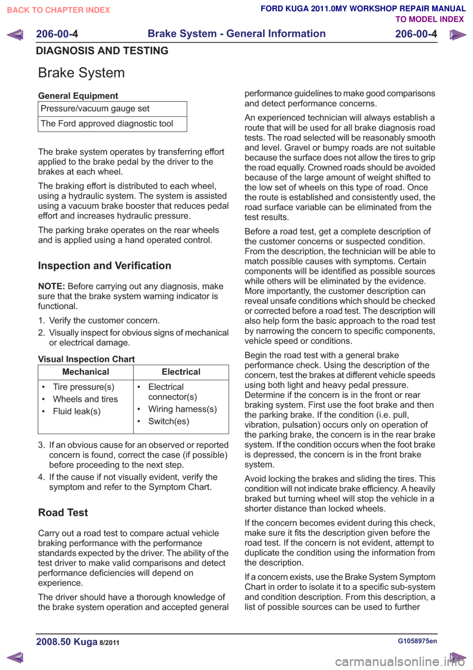
Brake System
General EquipmentPressure/vacuum gauge set
The Ford approved diagnostic tool
The brake system operates by transferring effort
applied to the brake pedal by the driver to the
brakes at each wheel.
The braking effort is distributed to each wheel,
using a hydraulic system. The system is assisted
using a vacuum brake booster that reduces pedal
effort and increases hydraulic pressure.
The parking brake operates on the rear wheels
and is applied using a hand operated control.
Inspection and Verification
NOTE: Before carrying out any diagnosis, make
sure that the brake system warning indicator is
functional.
1. Verify the customer concern.
2. Visually inspect for obvious signs of mechanical or electrical damage.
Visual Inspection Chart
Electrical
Mechanical
• Electricalconnector(s)
• Wiring harness(s)
• Switch(es)
• Tire pressure(s)
• Wheels and tires
• Fluid leak(s)
3. If an obvious cause for an observed or reported concern is found, correct the case (if possible)
before proceeding to the next step.
4. If the cause if not visually evident, verify the symptom and refer to the Symptom Chart.
Road Test
Carry out a road test to compare actual vehicle
braking performance with the performance
standards expected by the driver. The ability of the
test driver to make valid comparisons and detect
performance deficiencies will depend on
experience.
The driver should have a thorough knowledge of
the brake system operation and accepted general performance guidelines to make good comparisons
and detect performance concerns.
An experienced technician will always establish a
route that will be used for all brake diagnosis road
tests. The road selected will be reasonably smooth
and level. Gravel or bumpy roads are not suitable
because the surface does not allow the tires to grip
the road equally. Crowned roads should be avoided
because of the large amount of weight shifted to
the low set of wheels on this type of road. Once
the route is established and consistently used, the
road surface variable can be eliminated from the
test results.
Before a road test, get a complete description of
the customer concerns or suspected condition.
From the description, the technician will be able to
match possible causes with symptoms. Certain
components will be identified as possible sources
while others will be eliminated by the evidence.
More importantly, the customer description can
reveal unsafe conditions which should be checked
or corrected before a road test. The description will
also help form the basic approach to the road test
by narrowing the concern to specific components,
vehicle speed or conditions.
Begin the road test with a general brake
performance check. Using the description of the
concern, test the brakes at different vehicle speeds
using both light and heavy pedal pressure.
Determine if the concern is in the front or rear
braking system. First use the foot brake and then
the parking brake. If the condition (i.e. pull,
vibration, pulsation) occurs only on operation of
the parking brake, the concern is in the rear brake
system. If the condition occurs when the foot brake
is depressed, the concern is in the front brake
system.
Avoid locking the brakes and sliding the tires. This
condition will not indicate brake efficiency. A heavily
braked but turning wheel will stop the vehicle in a
shorter distance than locked wheels.
If the concern becomes evident during this check,
make sure it fits the description given before the
road test. If the concern is not evident, attempt to
duplicate the condition using the information from
the description.
If a concern exists, use the Brake System Symptom
Chart in order to isolate it to a specific sub-system
and condition description. From this description, a
list of possible sources can be used to further
G1058975en2008.50 Kuga8/2011
206-00-
4
Brake System - General Information
206-00- 4
DIAGNOSIS AND TESTING
TO MODEL INDEX
BACK TO CHAPTER INDEX
FORD KUGA 2011.0MY WORKSHOP REPAIR MANUAL
Page 1344 of 2057
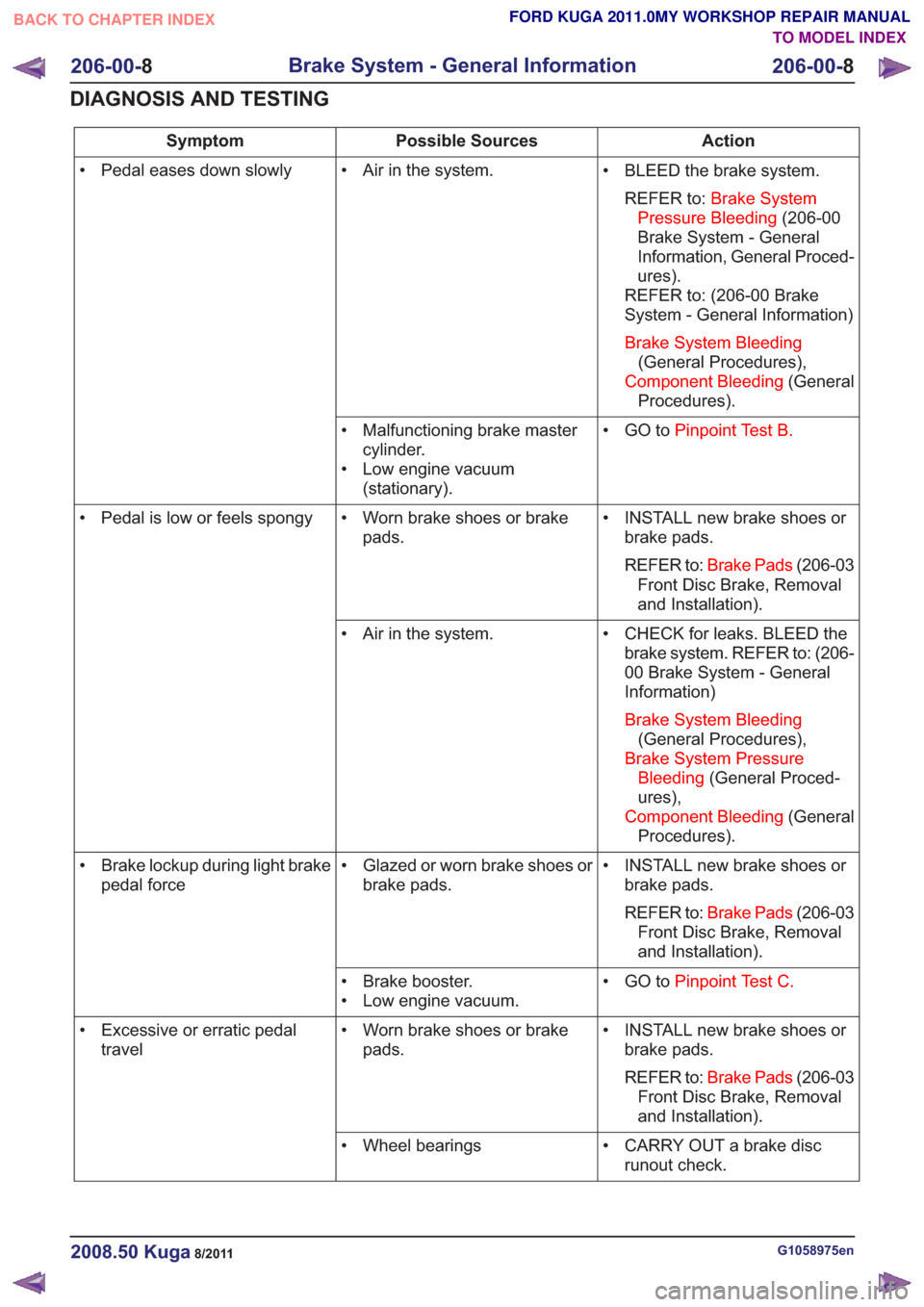
Action
Possible Sources
Symptom
• BLEED the brake system.REFER to: Brake System
Pressure Bleeding (206-00
Brake System - General
Information, General Proced-
ures).
REFER to: (206-00 Brake
System - General Information)
Brake System Bleeding (General Procedures),
Component Bleeding (General
Procedures).
• Air in the system.
• Pedal eases down slowly
• GO toPinpoint Test B.
• Malfunctioning brake master
cylinder.
• Low engine vacuum (stationary).
• INSTALL new brake shoes orbrake pads.
REFER to: Brake Pads (206-03
Front Disc Brake, Removal
and Installation).
• Worn brake shoes or brake
pads.
• Pedal is low or feels spongy
• CHECK for leaks. BLEED thebrake system. REFER to: (206-
00 Brake System - General
Information)
Brake System Bleeding (General Procedures),
Brake System Pressure Bleeding (General Proced-
ures),
Component Bleeding (General
Procedures).
• Air in the system.
• INSTALL new brake shoes orbrake pads.
REFER to: Brake Pads (206-03
Front Disc Brake, Removal
and Installation).
• Glazed or worn brake shoes or
brake pads.
• Brake lockup during light brake
pedal force
• GO toPinpoint Test C.
• Brake booster.
• Low engine vacuum.
• INSTALL new brake shoes orbrake pads.
REFER to: Brake Pads (206-03
Front Disc Brake, Removal
and Installation).
• Worn brake shoes or brake
pads.
• Excessive or erratic pedal
travel
• CARRY OUT a brake discrunout check.
• Wheel bearings
G1058975en2008.50 Kuga8/2011
206-00-
8
Brake System - General Information
206-00- 8
DIAGNOSIS AND TESTING
TO MODEL INDEX
BACK TO CHAPTER INDEX
FORD KUGA 2011.0MY WORKSHOP REPAIR MANUAL
Page 1345 of 2057
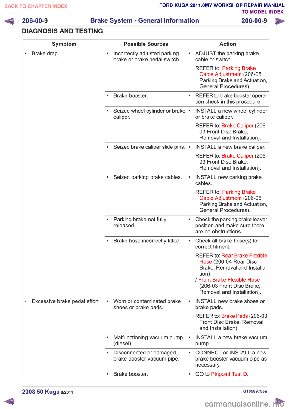
Action
Possible Sources
Symptom
• ADJUST the parking brakecable or switch
REFER to: Parking Brake
Cable Adjustment (206-05
Parking Brake and Actuation,
General Procedures).
• Incorrectly adjusted parking
brake or brake pedal switch
• Brake drag
• REFER to brake booster opera-tion check in this procedure.
• Brake booster.
• INSTALL a new wheel cylinderor brake caliper.
REFER to: Brake Caliper (206-
03 Front Disc Brake,
Removal and Installation).
• Seized wheel cylinder or brake
caliper.
• INSTALL a new brake caliper.REFER to: Brake Caliper (206-
03 Front Disc Brake,
Removal and Installation).
• Seized brake caliper slide pins.
• INSTALL new parking brakecables.
REFER to: Parking Brake
Cable Adjustment (206-05
Parking Brake and Actuation,
General Procedures).
• Seized parking brake cables.
• Check the parking brake leaverposition and make sure there
are no obstructions.
• Parking brake not fully
released.
• Check all brake hose(s) forcorrect fitment.
REFER to: Rear Brake Flexible
Hose (206-04 Rear Disc
Brake, Removal and Installa-
tion)
/ Front Brake Flexible Hose
(206-03 Front Disc Brake,
Removal and Installation).
• Brake hose incorrectly fitted.
• INSTALL new brake shoes orbrake pads.
REFER to: Brake Pads (206-03
Front Disc Brake, Removal
and Installation).
• Worn or contaminated brake
shoes or brake pads.
• Excessive brake pedal effort
• INSTALL a new brake vacuumpump.
• Malfunctioning vacuum pump
(diesel).
• CONNECT or INSTALL a newbrake booster vacuum pipe as
necessary.
• Disconnected or damaged
brake booster vacuum pipe.
• GO toPinpoint Test D.
• Brake booster.
G1058975en2008.50 Kuga8/2011
206-00- 9
Brake System - General Information
206-00- 9
DIAGNOSIS AND TESTING
TO MODEL INDEX
BACK TO CHAPTER INDEX
FORD KUGA 2011.0MY WORKSHOP REPAIR MANUAL
Page 1348 of 2057
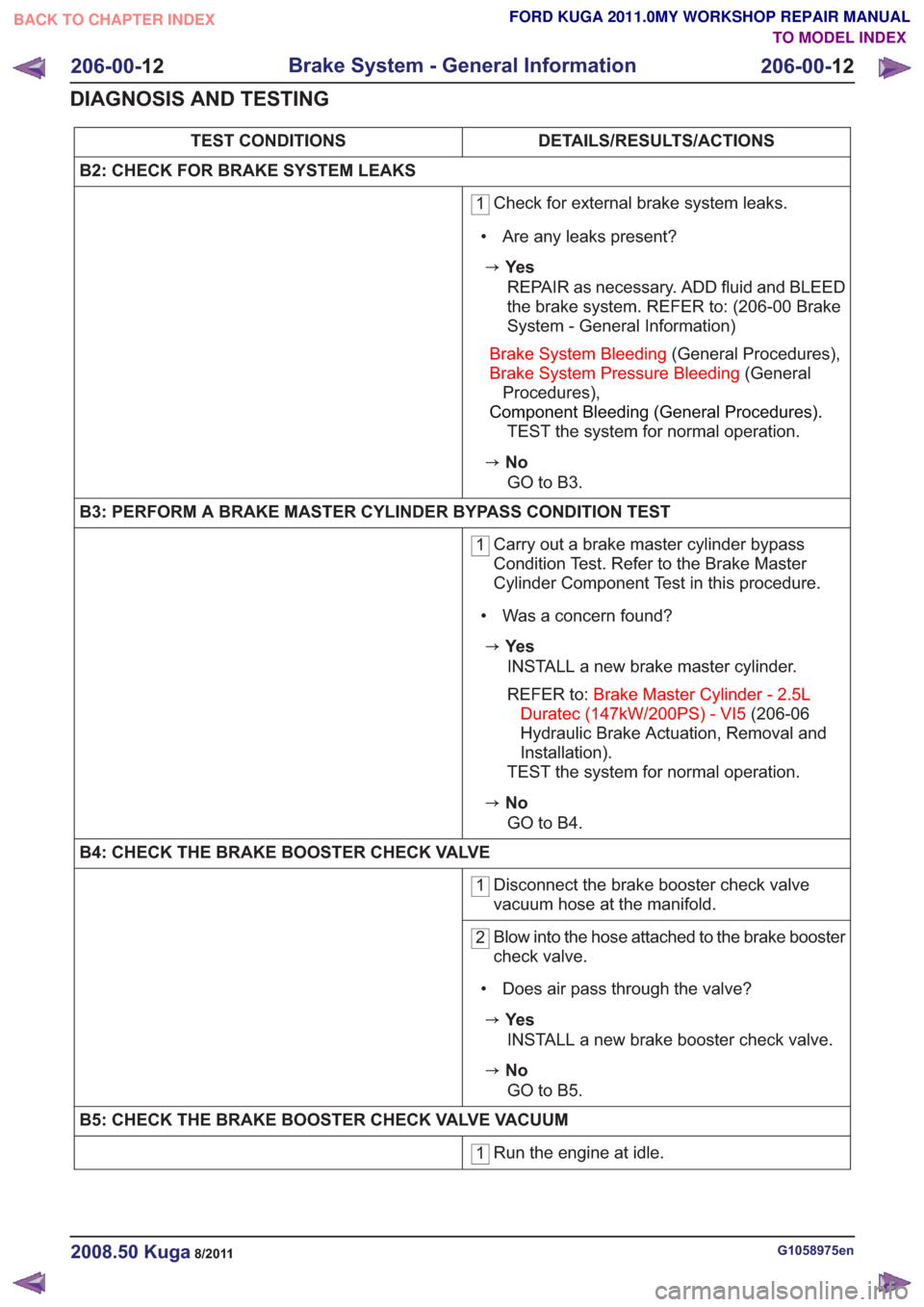
DETAILS/RESULTS/ACTIONS
TEST CONDITIONS
B2: CHECK FOR BRAKE SYSTEM LEAKS
1 Check for external brake system leaks.
• Are any leaks present?
zYe s REPAIR as necessary. ADD fluid and BLEED
the brake system. REFER to: (206-00 Brake
System - General Information)
Brake System Bleeding (General Procedures),
Brake System Pressure Bleeding (General
Procedures),
Component Bleeding (General Procedures).
TEST the system for normal operation.
zNo
GO to B3.
B3: PERFORM A BRAKE MASTER CYLINDER BYPASS CONDITION TEST
1 Carry out a brake master cylinder bypass
Condition Test. Refer to the Brake Master
Cylinder Component Test in this procedure.
• Was a concern found?
zYe s INSTALL a new brake master cylinder.
REFER to: Brake Master Cylinder - 2.5L
Duratec (147kW/200PS) - VI5 (206-06
Hydraulic Brake Actuation, Removal and
Installation).
TEST the system for normal operation.
zNo
GO to B4.
B4: CHECK THE BRAKE BOOSTER CHECK VALVE
1 Disconnect the brake booster check valve
vacuum hose at the manifold.
2Blow into the hose attached to the brake booster
check valve.
• Does air pass through the valve?
zYe s INSTALL a new brake booster check valve.
zNoGO to B5.
B5: CHECK THE BRAKE BOOSTER CHECK VALVE VACUUM
1 Run the engine at idle.
G1058975en2008.50 Kuga8/2011
206-00-
12
Brake System - General Information
206-00- 12
DIAGNOSIS AND TESTING
TO MODEL INDEX
BACK TO CHAPTER INDEX
FORD KUGA 2011.0MY WORKSHOP REPAIR MANUAL
Page 1349 of 2057
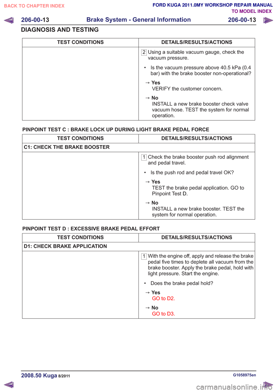
DETAILS/RESULTS/ACTIONS
TEST CONDITIONS
2 Using a suitable vacuum gauge, check the
vacuum pressure.
• Is the vacuum pressure above 40.5 kPa (0.4 bar) with the brake booster non-operational?
zYe s
VERIFY the customer concern.
zNoINSTALL a new brake booster check valve
vacuum hose. TEST the system for normal
operation.
PINPOINT TEST C : BRAKE LOCK UP DURING LIGHT BRAKE PEDAL FORCE
DETAILS/RESULTS/ACTIONS
TEST CONDITIONS
C1: CHECK THE BRAKE BOOSTER
1 Check the brake booster push rod alignment
and pedal travel.
• Is the push rod and pedal travel OK?
zYe s TEST the brake pedal application. GO to
Pinpoint Test D.
zNo
INSTALL a new brake booster. TEST the
system for normal operation.
PINPOINT TEST D : EXCESSIVE BRAKE PEDAL EFFORT
DETAILS/RESULTS/ACTIONS
TEST CONDITIONS
D1: CHECK BRAKE APPLICATION
1 With the engine off, apply and release the brake
pedal five times to deplete all vacuum from the
brake booster. Apply the brake pedal, hold with
light pressure. Start the engine.
• Does the brake pedal hold?
zYe s GO to D2 .
zNo
GO to D3 .
G1058975en2008.50 Kuga8/2011
206-00-13
Brake System - General Information
206-00- 13
DIAGNOSIS AND TESTING
TO MODEL INDEX
BACK TO CHAPTER INDEX
FORD KUGA 2011.0MY WORKSHOP REPAIR MANUAL
Page 1350 of 2057
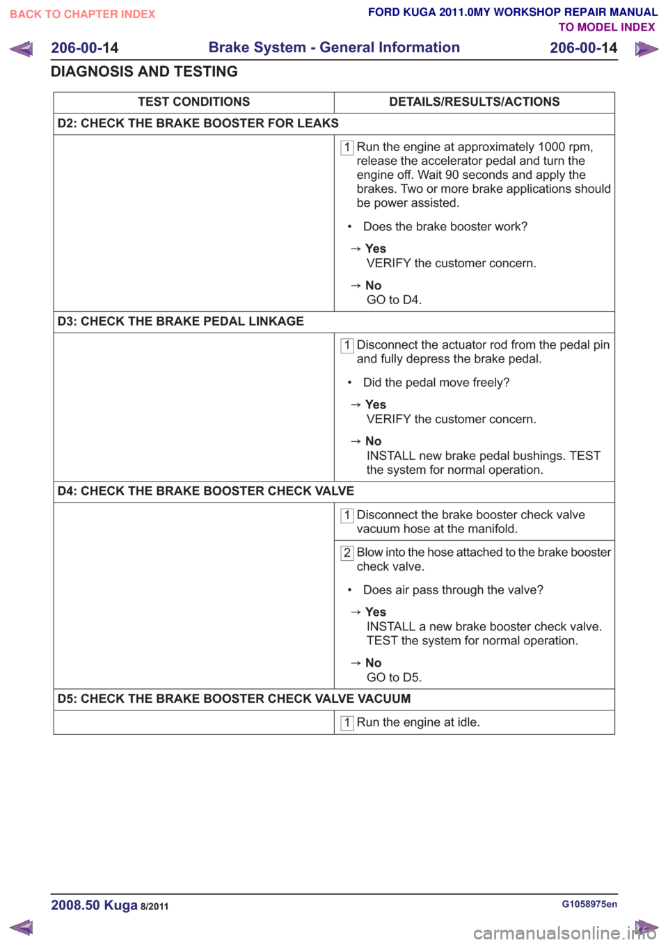
DETAILS/RESULTS/ACTIONS
TEST CONDITIONS
D2: CHECK THE BRAKE BOOSTER FOR LEAKS
1 Run the engine at approximately 1000 rpm,
release the accelerator pedal and turn the
engine off. Wait 90 seconds and apply the
brakes. Two or more brake applications should
be power assisted.
• Does the brake booster work?
zYe s VERIFY the customer concern.
zNoGO to D4 .
D3: CHECK THE BRAKE PEDAL LINKAGE
1 Disconnect the actuator rod from the pedal pin
and fully depress the brake pedal.
• Did the pedal move freely?
zYe s VERIFY the customer concern.
zNoINSTALL new brake pedal bushings. TEST
the system for normal operation.
D4: CHECK THE BRAKE BOOSTER CHECK VALVE
1 Disconnect the brake booster check valve
vacuum hose at the manifold.
2Blow into the hose attached to the brake booster
check valve.
• Does air pass through the valve?
zYe s INSTALL a new brake booster check valve.
TEST the system for normal operation.
zNoGO to D5 .
D5: CHECK THE BRAKE BOOSTER CHECK VALVE VACUUM
1 Run the engine at idle.
G1058975en2008.50 Kuga8/2011
206-00-
14
Brake System - General Information
206-00- 14
DIAGNOSIS AND TESTING
TO MODEL INDEX
BACK TO CHAPTER INDEX
FORD KUGA 2011.0MY WORKSHOP REPAIR MANUAL