2011 FORD KUGA brakes
[x] Cancel search: brakesPage 1856 of 2057
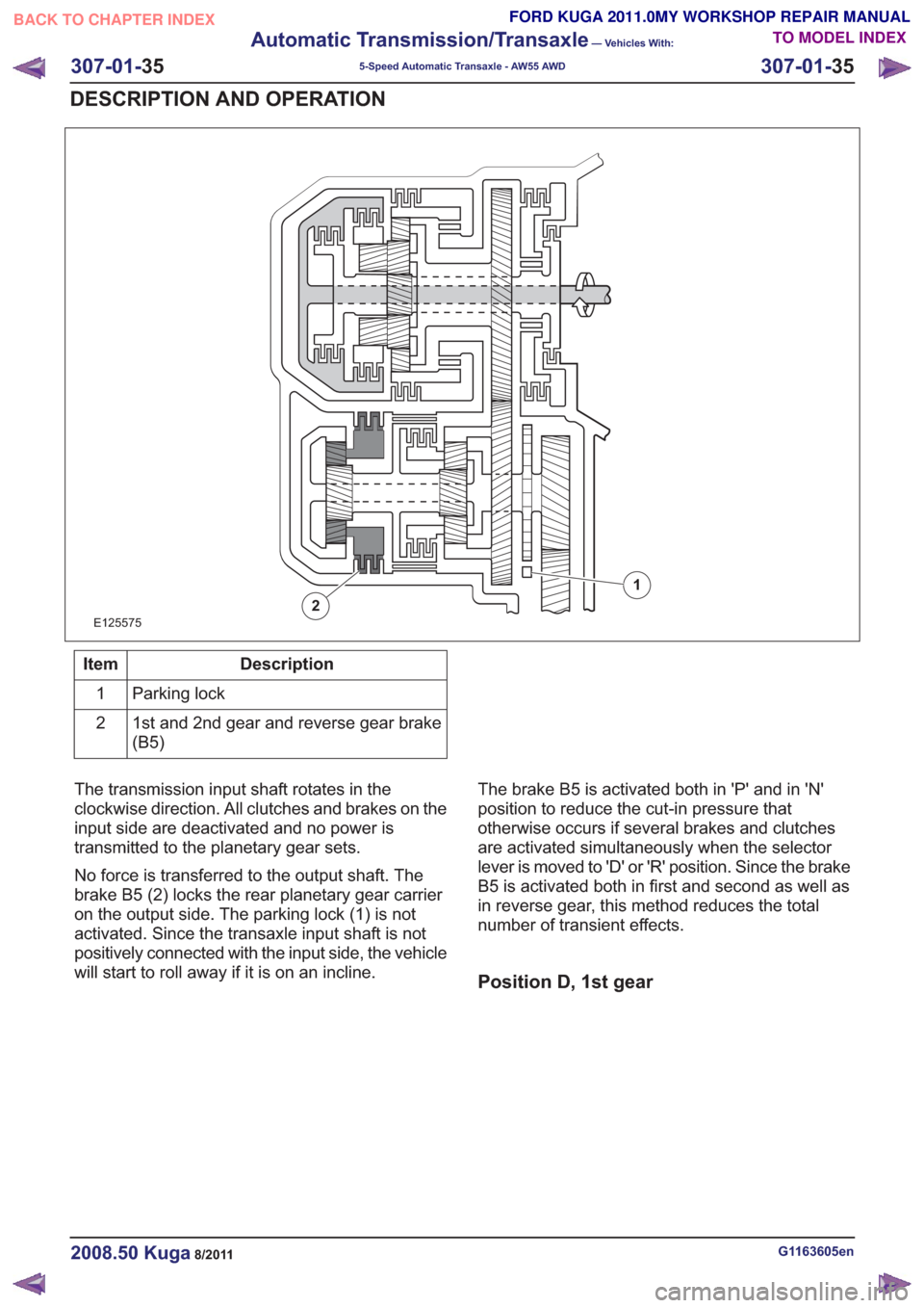
E125575
1
2
Description
Item
Parking lock
1
1st and 2nd gear and reverse gear brake
(B5)
2
The transmission input shaft rotates in the
clockwise direction. All clutches and brakes on the
input side are deactivated and no power is
transmitted to the planetary gear sets.
No force is transferred to the output shaft. The
brake B5 (2) locks the rear planetary gear carrier
on the output side. The parking lock (1) is not
activated. Since the transaxle input shaft is not
positively connected with the input side, the vehicle
will start to roll away if it is on an incline. The brake B5 is activated both in 'P' and in 'N'
position to reduce the cut-in pressure that
otherwise occurs if several brakes and clutches
are activated simultaneously when the selector
lever is moved to 'D' or 'R' position. Since the brake
B5 is activated both in first and second as well as
in reverse gear, this method reduces the total
number of transient effects.
Position D, 1st gear
G1163605en2008.50 Kuga8/2011
307-01-
35
Automatic Transmission/Transaxle
— Vehicles With:
5-Speed Automatic Transaxle - AW55 AWD
307-01- 35
DESCRIPTION AND OPERATION
TO MODEL INDEX
BACK TO CHAPTER INDEX
FORD KUGA 2011.0MY WORKSHOP REPAIR MANUAL
Page 1858 of 2057
E127359
1
2
3
4
5
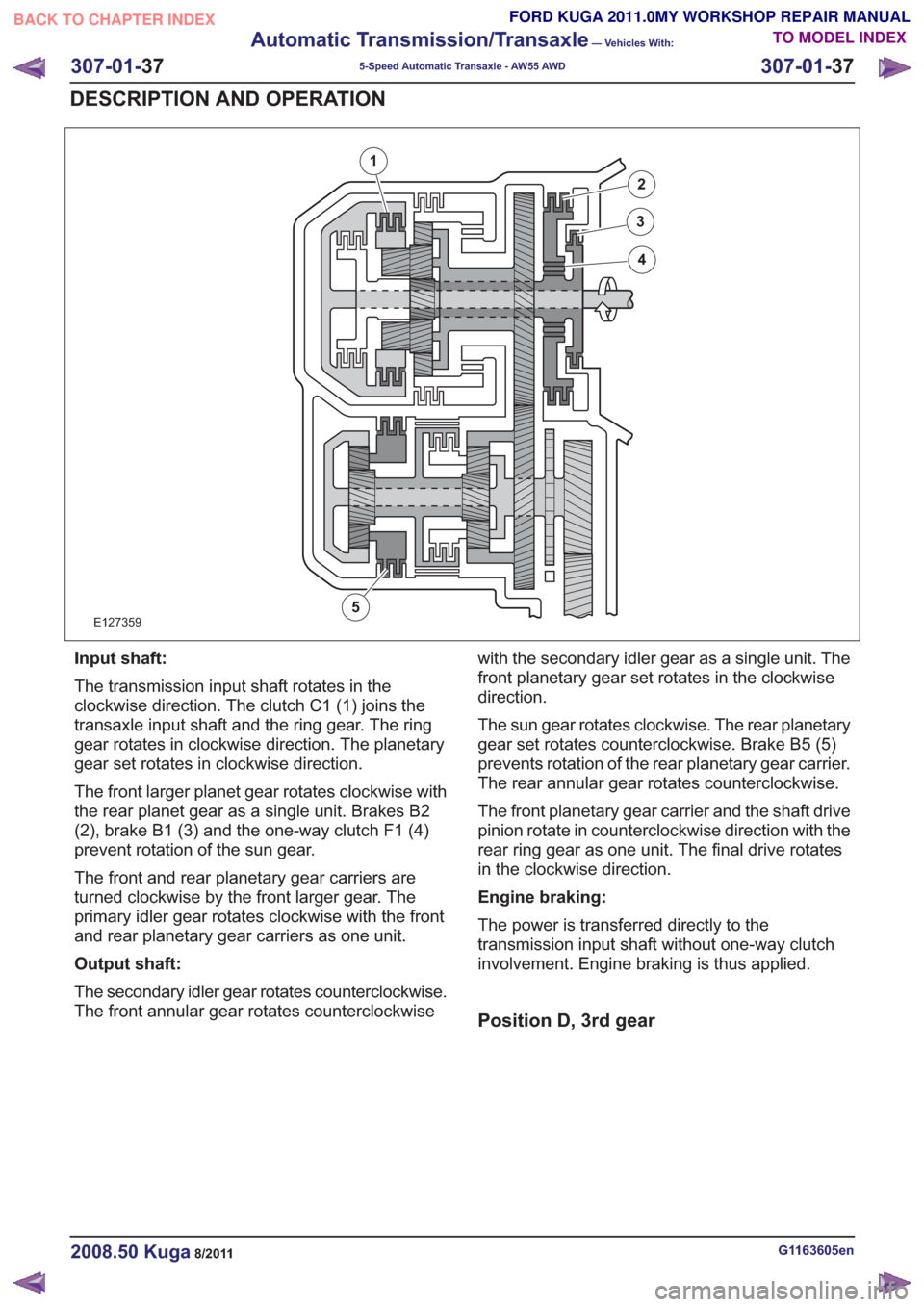
Input shaft:
The transmission input shaft rotates in the
clockwise direction. The clutch C1 (1) joins the
transaxle input shaft and the ring gear. The ring
gear rotates in clockwise direction. The planetary
gear set rotates in clockwise direction.
The front larger planet gear rotates clockwise with
the rear planet gear as a single unit. Brakes B2
(2), brake B1 (3) and the one-way clutch F1 (4)
prevent rotation of the sun gear.
The front and rear planetary gear carriers are
turned clockwise by the front larger gear. The
primary idler gear rotates clockwise with the front
and rear planetary gear carriers as one unit.
Output shaft:
The secondary idler gear rotates counterclockwise.
The front annular gear rotates counterclockwisewith the secondary idler gear as a single unit. The
front planetary gear set rotates in the clockwise
direction.
The sun gear rotates clockwise. The rear planetary
gear set rotates counterclockwise. Brake B5 (5)
prevents rotation of the rear planetary gear carrier.
The rear annular gear rotates counterclockwise.
The front planetary gear carrier and the shaft drive
pinion rotate in counterclockwise direction with the
rear ring gear as one unit. The final drive rotates
in the clockwise direction.
Engine braking:
The power is transferred directly to the
transmission input shaft without one-way clutch
involvement. Engine braking is thus applied.
Position D, 3rd gear
G1163605en2008.50 Kuga8/2011
307-01-
37
Automatic Transmission/Transaxle
— Vehicles With:
5-Speed Automatic Transaxle - AW55 AWD
307-01- 37
DESCRIPTION AND OPERATION
TO MODEL INDEX
BACK TO CHAPTER INDEX
FORD KUGA 2011.0MY WORKSHOP REPAIR MANUAL
Page 1859 of 2057
E127360
1
2
3
4
5
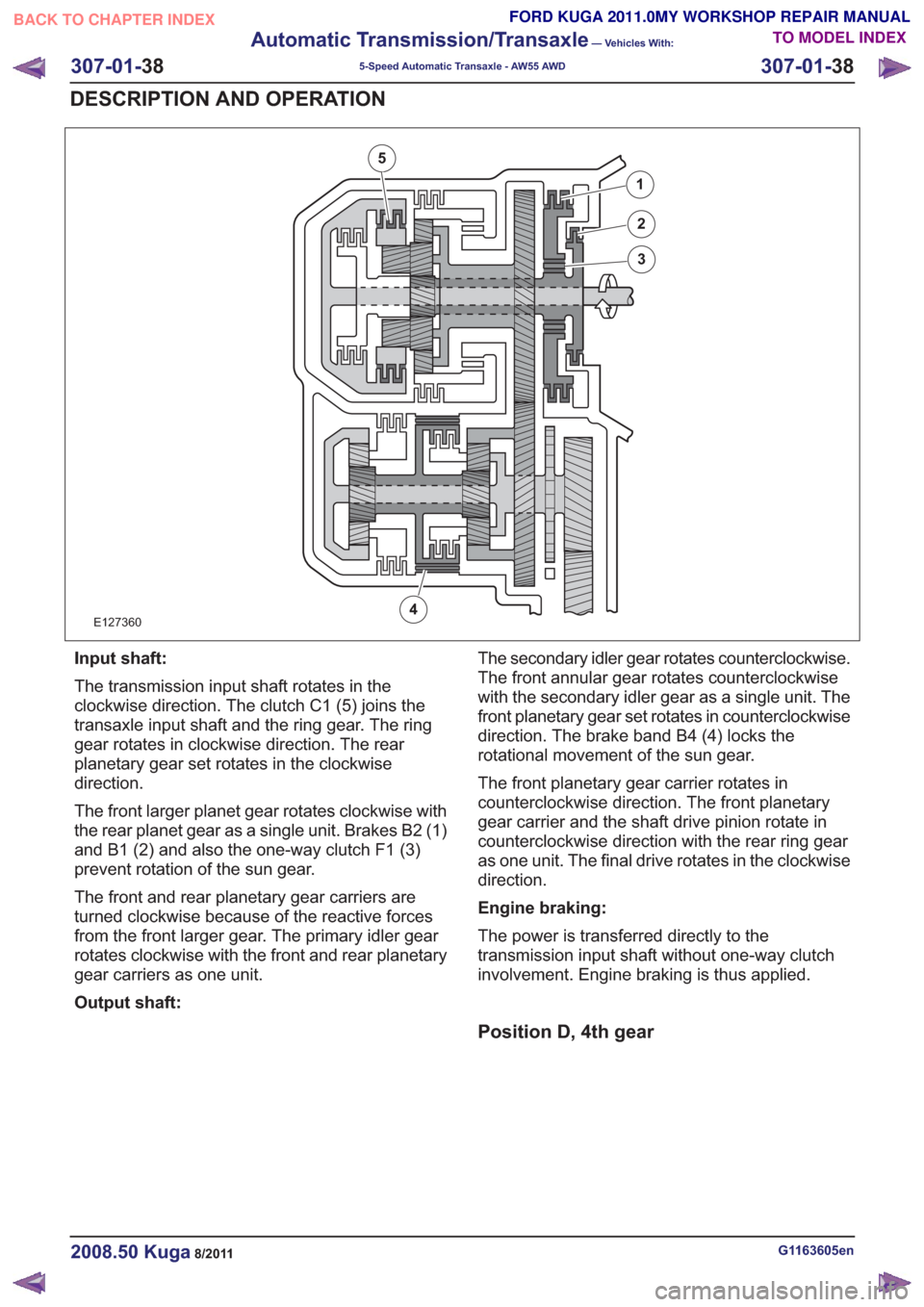
Input shaft:
The transmission input shaft rotates in the
clockwise direction. The clutch C1 (5) joins the
transaxle input shaft and the ring gear. The ring
gear rotates in clockwise direction. The rear
planetary gear set rotates in the clockwise
direction.
The front larger planet gear rotates clockwise with
the rear planet gear as a single unit. Brakes B2 (1)
and B1 (2) and also the one-way clutch F1 (3)
prevent rotation of the sun gear.
The front and rear planetary gear carriers are
turned clockwise because of the reactive forces
from the front larger gear. The primary idler gear
rotates clockwise with the front and rear planetary
gear carriers as one unit.
Output shaft:The secondary idler gear rotates counterclockwise.
The front annular gear rotates counterclockwise
with the secondary idler gear as a single unit. The
front planetary gear set rotates in counterclockwise
direction. The brake band B4 (4) locks the
rotational movement of the sun gear.
The front planetary gear carrier rotates in
counterclockwise direction. The front planetary
gear carrier and the shaft drive pinion rotate in
counterclockwise direction with the rear ring gear
as one unit. The final drive rotates in the clockwise
direction.
Engine braking:
The power is transferred directly to the
transmission input shaft without one-way clutch
involvement. Engine braking is thus applied.
Position D, 4th gear
G1163605en2008.50 Kuga8/2011
307-01-
38
Automatic Transmission/Transaxle
— Vehicles With:
5-Speed Automatic Transaxle - AW55 AWD
307-01- 38
DESCRIPTION AND OPERATION
TO MODEL INDEX
BACK TO CHAPTER INDEX
FORD KUGA 2011.0MY WORKSHOP REPAIR MANUAL
Page 1867 of 2057
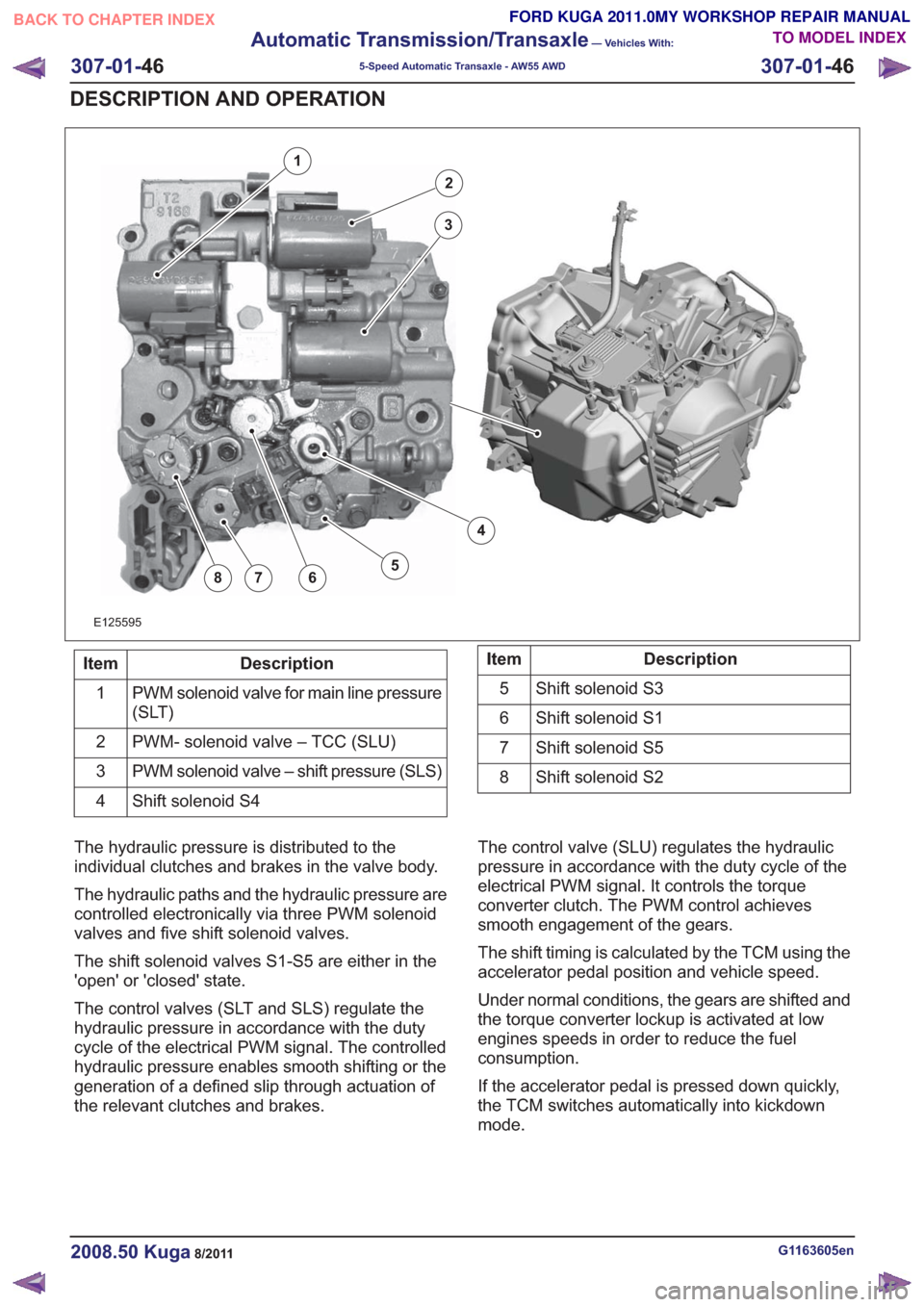
E125595
2
3
4
5678
1
Description
Item
PWM solenoid valve for main line pressure
(SLT)
1
PWM- solenoid valve – TCC (SLU)
2
PWM solenoid valve – shift pressure (SLS)
3
Shift solenoid S4
4Description
Item
Shift solenoid S3
5
Shift solenoid S1
6
Shift solenoid S5
7
Shift solenoid S2
8
The hydraulic pressure is distributed to the
individual clutches and brakes in the valve body.
The hydraulic paths and the hydraulic pressure are
controlled electronically via three PWM solenoid
valves and five shift solenoid valves.
The shift solenoid valves S1-S5 are either in the
'open' or 'closed' state.
The control valves (SLT and SLS) regulate the
hydraulic pressure in accordance with the duty
cycle of the electrical PWM signal. The controlled
hydraulic pressure enables smooth shifting or the
generation of a defined slip through actuation of
the relevant clutches and brakes. The control valve (SLU) regulates the hydraulic
pressure in accordance with the duty cycle of the
electrical PWM signal. It controls the torque
converter clutch. The PWM control achieves
smooth engagement of the gears.
The shift timing is calculated by the TCM using the
accelerator pedal position and vehicle speed.
Under normal conditions, the gears are shifted and
the torque converter lockup is activated at low
engines speeds in order to reduce the fuel
consumption.
If the accelerator pedal is pressed down quickly,
the TCM switches automatically into kickdown
mode.
G1163605en2008.50 Kuga8/2011
307-01-
46
Automatic Transmission/Transaxle
— Vehicles With:
5-Speed Automatic Transaxle - AW55 AWD
307-01- 46
DESCRIPTION AND OPERATION
TO MODEL INDEX
BACK TO CHAPTER INDEX
FORD KUGA 2011.0MY WORKSHOP REPAIR MANUAL
Page 1870 of 2057
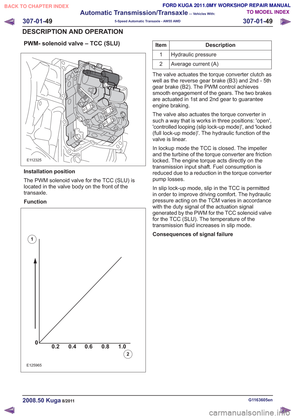
PWM- solenoid valve – TCC (SLU)
E112325
Installation position
The PWM solenoid valve for the TCC (SLU) is
located in the valve body on the front of the
transaxle.
Function
00.2 1.0 0.80.60.4
0
0.2 1.0
0.80.60.4
0
0.2 1.0
0.80.60.40
0.2 1.0 0.80.60.4
E125965
1
2
Description
Item
Hydraulic pressure
1
Average current (A)
2
The valve actuates the torque converter clutch as
well as the reverse gear brake (B3) and 2nd - 5th
gear brake (B2). The PWM control achieves
smooth engagement of the gears. The two brakes
are actuated in 1st and 2nd gear to guarantee
engine braking.
The valve also actuates the torque converter in
such a way that is works in three positions: 'open',
'controlled looping (slip lock-up mode)', and 'locked
(full lock-up mode)'. The hydraulic function of the
valve is linear.
In lockup mode the TCC is closed. The impeller
and the turbine of the torque converter are friction
locked. The engine torque acts directly on the
transmission input shaft. Fuel consumption is
reduced due to a reduction in the torque converter
pump losses.
In slip lock-up mode, slip in the TCC is permitted
in order to improve driving comfort. The hydraulic
pressure acting on the TCM varies in accordance
with the duty signal of the actuation signal
generated by the PWM for the TCC solenoid valve
for the TCC (SLU). The temperature of the
transmission fluid increases in slip mode.
Consequences of signal failure
G1163605en2008.50 Kuga8/2011
307-01- 49
Automatic Transmission/Transaxle
— Vehicles With:
5-Speed Automatic Transaxle - AW55 AWD
307-01- 49
DESCRIPTION AND OPERATION
TO MODEL INDEX
BACK TO CHAPTER INDEX
FORD KUGA 2011.0MY WORKSHOP REPAIR MANUAL
Page 1970 of 2057
Fuel System — Vehicles With: Fuel Additive Tank
General EquipmentFord diagnostic equipment
Principles of Operation
WARNINGS:
This procedure involves fuel additive
handling. Be prepared for fuel additive
spillage at all times and always observe
fuel handling precautions. Failure to follow
these instructions may result in personal
injury.
Eye, hand, ear protection and protective
clothing are required to be worn during
any general service or removal and
installation service procedure of fuel
additive system components. Failure to
follow this instruction may result in
personal injury.
In case of fuel additive fluid contact with
the skin or the eyes, flush immediately with
water for a minimum of 15 minutes and
seek prompt medical attention. Failure to
follow these instructions may result in
personal injury.
If fuel additive fluid is swallowed, call a
physician immediately. Rinse mouth
immediately with water, do not induce
vomiting. Failure to follow these
instructions may result in personal injury.
Always provide adequate ventilation when
working on the fuel additive fluid system
or related components. Failure to follow
these instructions may result in personal
injury.
Do not smoke or carry lighted tobacco or
open flame of any type when working on
or near any fuel related components.
Highly flammable vapors are always
present and may ignite. Failure to follow
these instructions may result in personal
injury.
CAUTION: Make sure the workshop area
in which the vehicle is being worked on is
as clean and as dust free as possible.
Foreign matter from working on clutches,
brakes or from machining or welding
operations can contaminate the fuel
system and may result in later malfunction. The fuel additive system is an on-board system
that allows the injection of an additive at each
refueling operation by the customer. The additive
quantity is proportional to the fuel quantity that has
been added. The fuel additive system module
controls the amount of additive fluid entering the
fuel tank at each refueling, A switch mounted on
the fuel filler flap is used to detect the start of the
refueling event and the fuel gauge that is mounted
within the fuel tank informs the fuel additive tank
module the quantity of actual fuel added.
Inspection and Verification
1. Verify the customer concern.
2. Visually inspect for obvious signs of leakage
and mechanical or electrical damage.
Visual Inspection Chart
Electrical
Mechanical
– Fuse(s)
– Fuel filler switch andmagnet
– Wiring harness(s)
– Electrical connector(s)
– Fuel additive system module
– Fuel additive tank module
– Instrument cluster
– Powertrain Control Module (PCM)
– Fuel level sensor
– Fuel additive tank
– Fuel additive tank
line(s)
– Fuel additive tank pipe(s)
– Fuel additive tank connector(s)
– Fuel tank filler cap
3. If an obvious cause for an observed or reported concern is found, correct the cause (if possible)
before proceeding to the next step
4. If the cause is not visually evident, REFER to the Ford diagnostic equipment.
G1080718en2008.50 Kuga8/2011
310-00- 2
Fuel System - General Information
310-00- 2
DIAGNOSIS AND TESTING
TO MODEL INDEX
BACK TO CHAPTER INDEX
FORD KUGA 2011.0MY WORKSHOP REPAIR MANUAL