2011 FORD KUGA Diagnostics
[x] Cancel search: DiagnosticsPage 185 of 2057

Instrument Cluster – Overview
Replacing the instrument cluster
When installing a new instrument cluster, the Ford
diagnostics device must be connected before
dismantling the instrument cluster, in order to load
the configuration data of the defective instrument
cluster using the "Installation of programmable
modules" routine. In addition, the value on the
odometer of the defective instrument cluster must
be noted, as this is required for configuration of the
new instrument cluster. If the odometer value
cannot be obtained from the instrument cluster
(display failure), the customer should supply the
approximate value.
When installing a new instrument cluster, the Ford
diagnostics device must be connected after
installation in order to download the configuration
data of the defective instrument cluster into the
new instrument cluster using the "Installation of
programmable modules" routine, and to configure
the newly installed instrument cluster to the PATS
system.
Self-diagnostic mode
1.
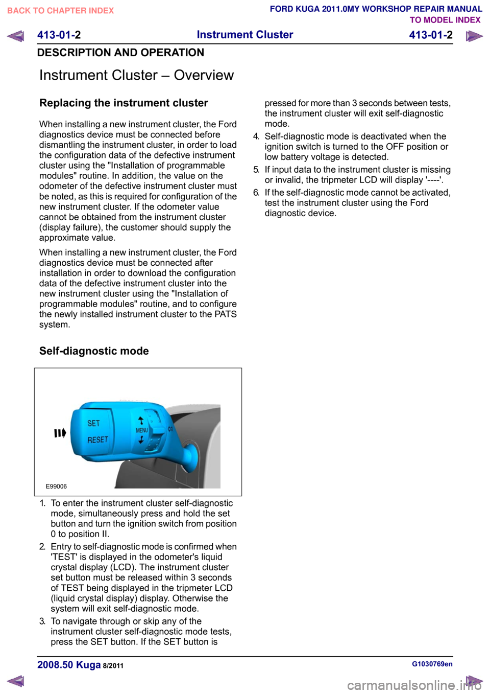
To enter the instrument cluster self-diagnostic
mode, simultaneously press and hold the set
button and turn the ignition switch from position
0 to position II.
2. Entry to self-diagnostic mode is confirmed when
'TEST' is displayed in the odometer's liquid
crystal display (LCD). The instrument cluster
set button must be released within 3 seconds
of TEST being displayed in the tripmeter LCD
(liquid crystal display) display. Otherwise the
system will exit self-diagnostic mode.
3. To navigate through or skip any of the
instrument cluster self-diagnostic mode tests,
press the SET button. If the SET button is pressed for more than 3 seconds between tests,
the instrument cluster will exit self-diagnostic
mode.
4. Self-diagnostic mode is deactivated when the
ignition switch is turned to the OFF position or
low battery voltage is detected.
5. If input data to the instrument cluster is missing
or invalid, the tripmeter LCD will display '----'.
6. If the self-diagnostic mode cannot be activated,
test the instrument cluster using the Ford
diagnostic device. G1030769en
2008.50 Kuga 8/2011 413-01-2
Instrument Cluster
413-01-2
DESCRIPTION AND OPERATIONTO MODEL INDEX
BACK TO CHAPTER INDEX
FORD KUGA 2011.0MY WORKSHOP REPAIR MANUALE99006
Page 216 of 2057

Parking Aid — Vehicles With: Front Parking Aid
Refer to Wiring Diagrams Section 413-13, for
schematic and connector information.
General Equipment
Ford diagnostic equipment
Principles of Operation
The ultrasonic parking aid system activates when
the ignition switch is turned to the RUN and when
the parking brake is OFF. If a front parking aid
switch is fitted the system will be de-activated and
a light emitting diode (LED) will indicate the state
of the system. A lit LED will indicate that the system
is currently deactivated. The parking aid system
will be disabled if a fault is detected in one of the
four front parking aid sensors, the parking aid
speaker or the parking aid module. An error tone
approximately 3 seconds long will be emitted from
the rear parking aid speaker if a fault is detected.
If the rear parking aid speaker is inoperative the
error tone will sound from the front parking aid
speaker.
Inspection and Verification
1. Verify the customer concern. 2. Visually inspect for obvious signs of electrical
damage.
Visual Inspection Chart Electrical
– Fuse(s)
– Wiring harness(s)
– Electrical connector(s)
– Battery junction box (BJB)
– Front parking aid sensor(s)
– Front parking aid speaker
– Parking aid module
3. If an obvious cause for an observed or reported concern is found, correct the cause (if possible)
before proceeding to the next step
4. If the cause is not visually evident, connect the Ford diagnostic equipment to the data link
connector (DLC) and select the vehicle system
to be tested from the diagnostic menu.
5. Retrieve the Diagnostic Trouble Code (DTC)s and refer to the DTC Index.
6. If no DTCs are retrieved or there is no communication with the module, proceed to the
Symptom Chart to continue diagnostics.
Diagnostic Trouble Codes (DTC) Index
DTC Index Action
Possible Source
Description
DTC
Check the circuit 8-GN9
(WH/GN) for short to battery.
IF the circuit is OK, INSTALL
a new parking aid module.
REFER to:Parking Aid
Module (413-13 Parking
Aid, Removal and Installa-
tion).
TEST the system for normal
operation.
• Parking aid sensor signal
circuit.
• Parking aid module.
Front outer left sensor signal
circuit short to battery
C1711
GO toPinpoint Test C.
• Parking aid sensor signal
circuit.
• Parking aid sensor.
• Parking aid module.
Front outer left sensor signal
circuit open or short to
ground
C1712 G325369en
2008.50 Kuga 8/2011 413-13-17
Parking Aid
413-13-17
DIAGNOSIS AND TESTINGTO MODEL INDEX
BACK TO CHAPTER INDEX
FORD KUGA 2011.0MY WORKSHOP REPAIR MANUAL
Page 228 of 2057

Parking Aid — Vehicles With: Rear Parking Aid
Refer to
Wiring Diagrams Section 413-13, for
schematic and connector information. General Equipment
Ford diagnostic equipment
Principles of Operation
NOTE: The rear parking aid system will be
de-activated when a Ford rear trailer tow module
is attached to the vehicle.
The ultrasonic parking aid system will default to
enabled when the ignition switch is turned to the
RUN position, the system is activated by selecting
reverse gear. The parking aid system will be
disabled if a fault is detected in one of the four rear
parking aid sensors, the parking aid speaker or the
parking aid module. An error tone approximately
3 seconds long will be emitted from the rear parking
aid speaker if a fault is detected. The rear parking
aid speaker will also sound for approximately 3
seconds if an error is detected at each ignition
cycle or if an error is detected when the system
has been activated.
Inspection and Verification
1. Verify the customer concern. 2. Visually inspect for obvious signs of electrical
damage.
Visual Inspection Chart Electrical
– Fuse(s)
– Wiring harness(s)
– Electrical connector(s)
– Battery junction box (BJB)
– Rear parking aid sensor(s)
– Rear parking aid speaker
– Parking aid module
3. If an obvious cause for an observed or reported concern is found, correct the cause (if possible)
before proceeding to the next step
4. If the cause is not visually evident, connect the Ford diagnostic equipment to the data link
connector (DLC) and select the vehicle system
to be tested from the diagnostic menu.
5. Retrieve the Diagnostic Trouble Code (DTC)s and refer to the DTC Index.
6. If no DTCs are retrieved or there is no communication with the module, proceed to the
Symptom Chart to continue diagnostics.
Diagnostic Trouble Codes (DTC) Index
DTC Index Action
Possible Source
Description
DTC
Check the circuit 8-GN22
(WH/GN) for short to battery.
IF the circuit is OK, INSTALL
a new parking aid module.
REFER to:Parking Aid
Module (413-13 Parking
Aid, Removal and Installa-
tion).
TEST the system for normal
operation.
• Parking aid sensor signal
circuit.
• Parking aid module.
Rear outer left sensor signal
circuit short to battery
C1699
GO toPinpoint Test C.
• Parking aid sensor signal
circuit.
• Parking aid sensor.
• Parking aid module.
Rear outer left sensor signal
circuit open or short to
ground
C1700 G295937en
2008.50 Kuga 8/2011 413-13-29
Parking Aid
413-13-29
DIAGNOSIS AND TESTINGTO MODEL INDEX
BACK TO CHAPTER INDEX
FORD KUGA 2011.0MY WORKSHOP REPAIR MANUAL
Page 266 of 2057

• Surface charge removal procedure
• Dynamic Response procedure for refined
decisiveness on battery diagnostics
• Upgradeable by SD card
• Export data feature to send data to infra red printer
• Voltmeter function
• Date and time indication with every test
• 23 languages included within the battery tester
Using the Midtronics EXP-1050 battery
tester
• Disconnect the battery ground cable at the battery negative (-) post. Note: if using this
battery tester on models where the ground cable
is not accessible, the battery does not have to
be removed from the vehicle and may be tested
using the vehicle's 'jump start post' if the battery
tester is set to the correct mode. In this case,
the battery must be disconnected at the positive
(+) post before testing.
• Connect the positive red clamp of the Midtronics
EXP-1050 battery tester to the battery positive
(+) post.
• Connect the negative black clamp of the Midtronics EXP-1050 battery tester to the
battery negative (-) post or jump start post as
appropriate.
A poor connection will prevent testing and the
battery tester will display the message CHECK
CONNECTION. If this message appears after you have correctly reconnected the clamps, clean the
terminals and reconnect.
It is recommended that batteries are always tested
using both battery posts. However, if used in 'jump
start post' mode, the Midtronics EXP-1050 battery
tester will compensate for the extra resistance of
the additional cable.
1.
Select BATTERY TEST or START-STOP
BATTERY TEST.
– Press the NEXT key to continue.
2. Select the BATTERY LOCATION
– UNDER HOOD
– UNDER SEAT
– OUT OF VEHICLE
– Press the NEXT key to continue.
3. Select the negative POST TYPE (IN-VEHICLE
ONLY)
– BATTERY POST
– JUMP START POST
– JUMP START POST (Battery Monitoring
Sensor)
– Press the NEXT key to continue.
4. Select the BATTERY RATING from the drop
down list.
– Press the NEXT key to test the battery.
5. If the battery under test is not listed in the drop
down list, it can still be selected with the
MANUAL ENTRY mode. This is item 11 of 11
in the list.
The Midtronics EXP-1050 battery tester will display
the word TESTING while it evaluates the battery.
Battery tester results and required actions Action
Battery Tester Reading
Return the battery to service
GOOD BATTERY
Fully recharge the battery and return it to service
GOOD - RECHARGE
Fully charge the battery and retest (failure to fully
charge the battery before retesting may cause false readings)
CHARGE & RETEST G1055063en
2008.50 Kuga 8/2011 414-00-5
Charging System - General Information
414-00-5
DIAGNOSIS AND TESTINGTO MODEL INDEX
BACK TO CHAPTER INDEX
FORD KUGA 2011.0MY WORKSHOP REPAIR MANUAL
Page 291 of 2057

3. If an obvious cause for an observed or reported
concern is found, correct the cause (if possible)
before proceeding to the next step.
4. If the cause is not visually evident, connect the Ford diagnostic equipment to the data link
connector (DLC).
5. SELECT the TOOLBOXmenu.
6. SELECT the ENTERTAINMENT/COMMUNICATION menu.7. SELECT the
SPEECH RECOGNITION
MODULE option and follow the instructions on
the display.
8. Retrieve the diagnostic trouble codes (DTC)s and refer to the Diagnostic Trouble Code (DTC)
Index Chart.
9. If no DTCs are retrieved or there is no communication with the module, proceed to the
Symptom Chart to continue diagnostics.
Diagnostic Trouble Code (DTC) Index Chart Action
Possible Source
Description/Condition
DTC
GO toPinpoint Test B.
Microphone defect or
short to ground
Microphone input circuit
failure
B1038
REFER to:Charging
System (414-00 Char-
ging System - General
Information, Diagnosis and Testing).
Battery voltage above
16 volts
Battery voltage high
B1317
REFER to:Charging
System (414-00 Char-
ging System - General
Information, Diagnosis and Testing).
Battery voltage below 9
volts
Battery voltage low
B1318
INSTALL a new PSEmodule. TEST the
system for normal oper- ation.
PSE module
PSE module failure
B1342
GO toPinpoint Test B.
Microphone defect or
not connected
Microphone input signal
circuit open
B1899
GO toPinpoint Test B.
No supply to micro-
phone
Microphone bias circuit
failure
B2272
REFER to the Ford
diagnostic equipment.
PSE module
Faulty module configura-
tion
B2477 G1189085en
2008.50 Kuga 8/2011 415-00-5
Information and Entertainment System -
General Information
415-00-5
DIAGNOSIS AND TESTINGTO MODEL INDEX
BACK TO CHAPTER INDEX
FORD KUGA 2011.0MY WORKSHOP REPAIR MANUAL
Page 299 of 2057

Audio System – Overview
Keycode entry - vehicle with standard
audio system
The keycode is entered via the MENU button and
the arrow buttons. The keycode is then confirmed
with the rotary/pushbutton in the middle of the unit.
Only a limited number of attempts to enter the
correct keycode are allowed. The number of
attempts already made is shown in the display.
Following every subsequent unsuccessful attempt,
an uninterrupted waiting period must be observed
before a further attempt can be made.
The display then shows "WAIT XX" and counts
down to "0", provided the ignition remains switched
on. Once this time has expired, a new attempt can
be made to enter the keycode.
After a certain number of unsuccessful attempts
at entering the keycode, the display will show
"LOCKED" or "SAFE". The customer will now be
unable to switch on the device.
The authorized Ford dealer can remove the lock
and can make up to three further attempts.
Vehicle Identification Number (VID) -
entry - vehicle with standard audio
system
It is often extremely difficult to return stolen audio
units which have been seized by the police to their
owners.
Therefore, many Ford audio units offer the option
of, for example, entering a vehicle identification
number into the unit.
For Ford audio systems, the abbreviation VID is
used to refer to the Vehicle Identification Number.
The VIN (chassis number) or, for instance, the number plate number can be entered and this
fulfills the security function.
The VIN is programmed ex works. If the unit is
replaced, the VIN is automatically transferred by
the diagnostics system during configuration.
Self-check routine - vehicles with
standard audio system.
The audio unit must be in radio mode before
entering the Self-Diagnostic Mode.
To enter the audio unit Self-Diagnostic Mode,
switch the audio unit ON. Press pre-set buttons 3
and 6 simultaneously and then release them again.
Keycode entry - vehicles with upgraded
audio system
The station keys are used to enter the keycode.
Station key 5 is used to confirm the keycode.
Only a limited number of attempts to enter the
correct keycode are allowed. The number of
attempts already made is shown in the display.
After the second unsuccessful attempt, the person
entering the keycode will have to wait for an
uninterrupted period of time before making the next
attempt.
The display then shows "WAIT XX" and counts
down to "0", provided the ignition remains switched
on. Once this time has expired, a new attempt can
be made to enter the keycode.
After a certain number of unsuccessful attempts
at entering the keycode, the display will show
"LOCKED" or "SAFE". The customer will now be
unable to switch on the device.
G1055645en
2008.50 Kuga 8/2011 415-01-3
Information and Entertainment System
415-01-3
DESCRIPTION AND OPERATIONTO MODEL INDEX
BACK TO CHAPTER INDEX
FORD KUGA 2011.0MY WORKSHOP REPAIR MANUALE99206 E99207
Page 1782 of 2057

Powertrain Control Module (PCM)
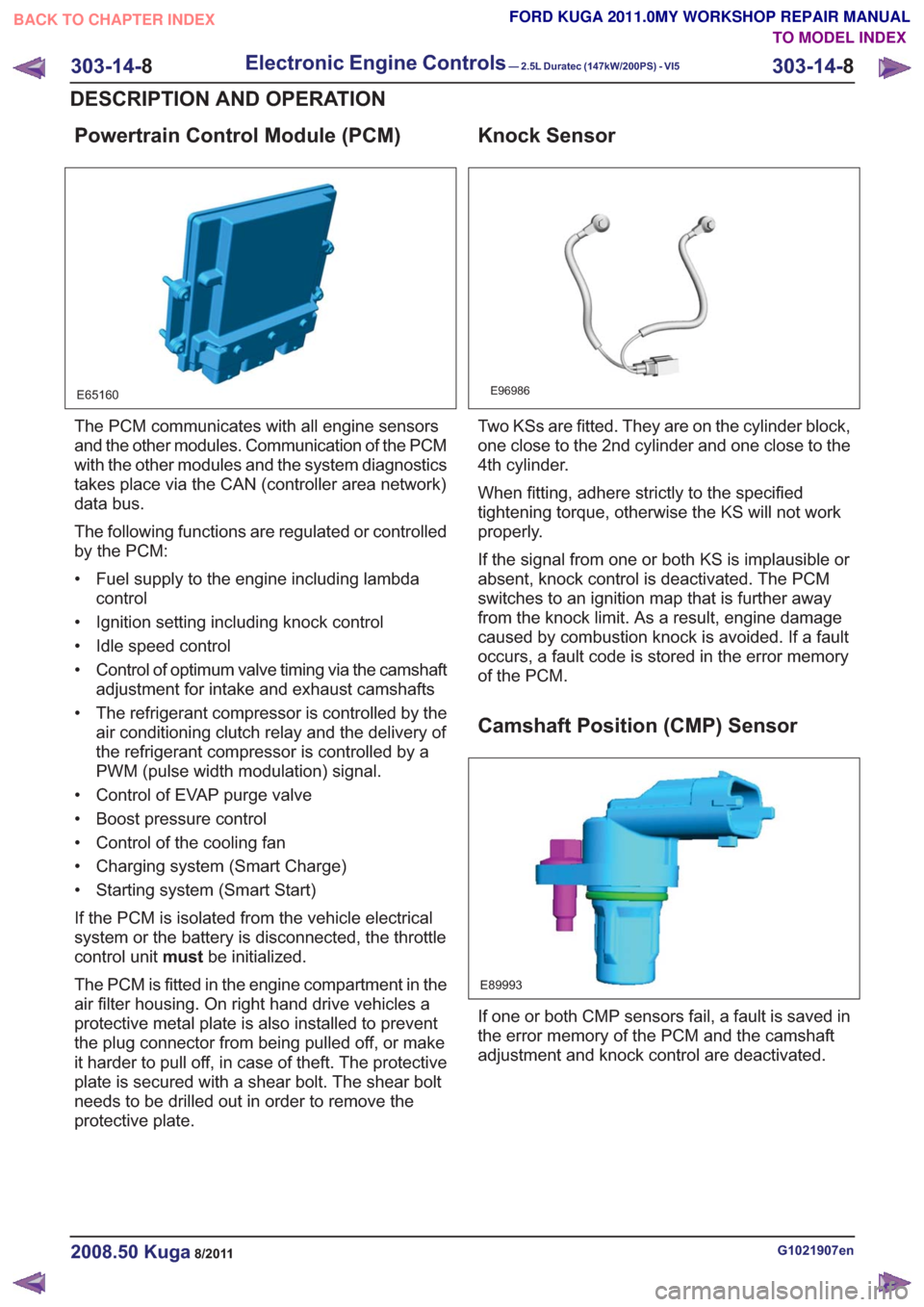
E65160
The PCM communicates with all engine sensors
and the other modules. Communication of the PCM
with the other modules and the system diagnostics
takes place via the CAN (controller area network)
data bus.
The following functions are regulated or controlled
by the PCM:
• Fuel supply to the engine including lambdacontrol
• Ignition setting including knock control
• Idle speed control
• Control of optimum valve timing via the camshaft adjustment for intake and exhaust camshafts
• The refrigerant compressor is controlled by the air conditioning clutch relay and the delivery of
the refrigerant compressor is controlled by a
PWM (pulse width modulation) signal.
• Control of EVAP purge valve
• Boost pressure control
• Control of the cooling fan
• Charging system (Smart Charge)
• Starting system (Smart Start)
If the PCM is isolated from the vehicle electrical
system or the battery is disconnected, the throttle
control unit mustbe initialized.
The PCM is fitted in the engine compartment in the
air filter housing. On right hand drive vehicles a
protective metal plate is also installed to prevent
the plug connector from being pulled off, or make
it harder to pull off, in case of theft. The protective
plate is secured with a shear bolt. The shear bolt
needs to be drilled out in order to remove the
protective plate.
Knock Sensor
E96986
Two KSs are fitted. They are on the cylinder block,
one close to the 2nd cylinder and one close to the
4th cylinder.
When fitting, adhere strictly to the specified
tightening torque, otherwise the KS will not work
properly.
If the signal from one or both KS is implausible or
absent, knock control is deactivated. The PCM
switches to an ignition map that is further away
from the knock limit. As a result, engine damage
caused by combustion knock is avoided. If a fault
occurs, a fault code is stored in the error memory
of the PCM.
Camshaft Position (CMP) Sensor
E89993
If one or both CMP sensors fail, a fault is saved in
the error memory of the PCM and the camshaft
adjustment and knock control are deactivated.
G1021907en2008.50 Kuga8/2011
303-14- 8
Electronic Engine Controls— 2.5L Duratec (147kW/200PS) - VI5303-14-
8
DESCRIPTION AND OPERATION
TO MODEL INDEX
BACK TO CHAPTER INDEX
FORD KUGA 2011.0MY WORKSHOP REPAIR MANUAL
Page 1796 of 2057

current value is reached. The PCM then
permanently connects the heating element to earth.
The catalyst monitor sensor is used by the PCM
to measure the oxygen content in the exhaust gas
in the TWC. If all the conditions for catalyst
diagnostics are met, based on this information the
PCM can check that the TWC is working
satisfactorily. The information is also used to
improve the air/fuel mixture adjustment.
The catalyst monitor sensor is similar in function
to an HO2S. The signal transmitted by the catalyst
monitor sensor changes sharply if the oxygen
content in the exhaust gas changes. For this
reason, catalyst monitor sensors are also called
"jump lambda sensors".
Fuel tank purging
The EVAP purge valve is only actuated by the PCM
if the coolant temperature is at least 60°C.
Actuation is done ground side by means of a PWM
signal. This makes it possible to have the full range
of opening widths, from fully closed to fully open.
The PCM determines from the operating conditions
when and how wide to open the EVAP tank purge
valve. If the EVAP purge valve is opened, the
engine sucks in ambient air through the activated
charcoal in the evaporative emission canister as
a result of the vacuum in the intake manifold. In
this way the adsorbed hydrocarbons are led to the
combustion chamber of the engine.
The EVAP tank purge valve is not actuated and
system cleaning is interrupted if the engine
switches to idle and/or a closed-loop control
process is initiated.
Power (battery voltage) is supplied via the
Powertrain Control Module relay in the BJB. The
solenoid coil resistance is between 17 and 24 ohms
at 20°C.
Engine speed control
The APP sensor provides the PCM with information
about the driver's request for acceleration.
The throttle control unit receives a corresponding
input signal from the PCM. An electric motor then
moves the throttle valve shaft by means of a set
of gears. The position of the throttle is continuously
recorded by the TP sensor. Information on throttle
position is processed and monitored by the PCM.
The TP sensor comprises two potentiometers.
These work in opposite ways to each other. In one
potentiometer, the resistance increases when the
throttle is opened, in the other it decreases. Thisallows the operation of the potentiometers to be
checked. The signal from the TP sensor is
amplified in the lower range (idle to a quarter open)
by the PCM to enable more precise control of the
throttle in this range. This is necessary because
the engine is very sensitive to changes in throttle
angle in this throttle opening range.
With the throttle valve position kept constant, the
ignition angle and the injected fuel quantity are
then varied to meet the torque demands.
Depending on the operating state of the engine, a
change in the position of the throttle flap may not
be necessary when the APP sensor changes.
If a fault develops in the throttle control unit, a
standby function is executed. This standby function
allows a slight opening of the throttle flap, so that
enough air passes through to allow limited engine
operation. For this purpose, there is a throttle flap
adjustment screw on the throttle housing. The
return spring closes the throttle flap until the stop
of the toothed segment touches the stop screw. In
this way a defined throttle flap gap is formed for
limp home mode.
The stop screw has a spring loaded pin, which
holds the throttle flap open for limp home mode.
In normal operating mode, this spring loaded pin
is pushed in by the force of the electric motor when
the throttle flap must be closed past the limp home
position (e.g. for idle speed control or overrun
shutoff).
Oil monitoring
The engine does not have an oil pressure
switch.
The oil level and oil quality are calculated.
Calculating the engine oil level
The oil level is determined by continuous
measurement of the capacitance (i.e. the ability to
store an electrical charge) between the two
capacitive elements of the engine oil
level/temperature/quality sensor. The different oil
levels cause the capacitance between the elements
to change. The data are recorded by the PCM and
converted into an oil level value. Temporary
fluctuations in oil level are automatically filtered out
by the PCM.
Calculating oil quality
The PCM calculates the oil quality from the oil level
measurement and the oil temperature measured
by the sensor, plus the engine speed and the
average fuel consumption. The driver is informed
about when an oil change is due.
G1021908en2008.50 Kuga8/2011
303-14- 22
Electronic Engine Controls— 2.5L Duratec (147kW/200PS) - VI5303-14-
22
DESCRIPTION AND OPERATION
TO MODEL INDEX
BACK TO CHAPTER INDEX
FORD KUGA 2011.0MY WORKSHOP REPAIR MANUAL