2011 FORD KUGA brakes
[x] Cancel search: brakesPage 1429 of 2057
HCU to check for sudden actuation of the brakes.
With the brake pedal pressed, the ABS module
triggers emergency braking if the rate of increase
of hydraulic pressure exceeds the predetermined
limit.
If the brake pedal is pressed so hard that the ABS
becomes active on the front wheels then the ABS
control unit increases the pressure to the rear
wheel brakes up to the ABS intervention threshold.
EBA operation continues until the driver releases
the brake pedal sufficiently for the hydraulic
pressure in the HCU to drop below a threshold
value stored in the ABS module.
Trailer stability control:If the vehicle is ordered
with a trailer coupling then the Trailer Stability
Control function is integrated in the ESP. The ESP
detects snaking when driving with a trailer and
reduces the speed of the vehicle and trailer through
adapted braking and, if necessary, by also reducing
the engine output until the snaking movement of
the trailer is corrected.
Roll-over protection: The ESP dynamically
determines the tipping tendency of the vehicle and
works in conjunction with the EBA system to
prevent the vehicle from tipping over during
dynamic maneuvers like lane changing or while
negotiating bends.
Emergency brake light: The emergency brake
light automatically switches on the hazard flasher
system to warn drivers of other vehicles that
emergency braking is being initiated. Based on a
defined delay value, the ABS/ESP module sends
a signal to the generic electronic module (GEM)
via the CAN data bus. The GEM activates the
hazard flasher system, that then flashes 7 times.
Prerequisites for activation of the emergency brake
light are:
• The speed is higher than 50 km/h.
• The brake pedal is being actuated.
• The deceleration is greater than 9 m/s².
To prevent activation on snow or ice, for example,
the following prerequisites must be met:
• The speed is higher than 50 km/h.
• The brake pedal is being actuated.
• ABS regulation takes place.
• The deceleration is greater than 6 m/s².
Tire pressure monitoring system: The tire
pressure monitoring system used in the Kuga is
able to detect loss of air in a tire at an early stage
and warn the driver. Because it can only compare
the behaviour of the tyres with each other, it is not possible to draw conclusions about the absolute
tyre pressure. It is also not possible to monitor the
spare tyre pressure. In order for the system to
operate correctly, the tyre pressures must be
regularly checked and corrected and the system
subsequently initialised (see below).
The tire pressure monitoring system used here,
depending on the equipment level, is built into the
anti-lock braking system (ABS) as an extra function
and therefore does not have its own sensors.
The ABS module measures the loss of pressure
in the tyres by calculation using the wheel speed
sensors of the ABS system. If a tyre loses
pressure, its diameter decreases and the speed of
the wheel therefore increases. If the ABS module
detects such a loss in pressure, it sends a signal
to the instrument cluster via the CAN bus and a
warning message is displayed in the message
centre. The warning threshold depends among
other things on the dimension of the tyres being
used, the vehicle operating conditions and the
status at the last initialisation. Since neither the
absolute tyre pressure nor the position of the tyre
is known, the pressure of all the tyres must be
checked and the system re-initialised after a tyre
pressure warning. If necessary, the cause of the
loss of pressure must be investigated.
Regular tyre pressure checks are still necessary.
The system must be initialised after a tyre is
changed, winter or summer tyres fitted, the
pressures corrected or adjusted to suit the vehicle
load. This can be done by the driver using the
driver information system. For further information,
see: Owner’s Manual.
Component Description
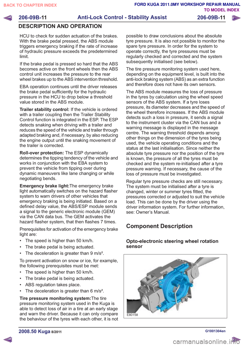
Opto-electronic steering wheel rotation
sensor
E80158
G1001304en2008.50 Kuga8/2011
206-09B-
11
Anti-Lock Control - Stability Assist
206-09B- 11
DESCRIPTION AND OPERATION
TO MODEL INDEX
BACK TO CHAPTER INDEX
FORD KUGA 2011.0MY WORKSHOP REPAIR MANUAL
Page 1430 of 2057
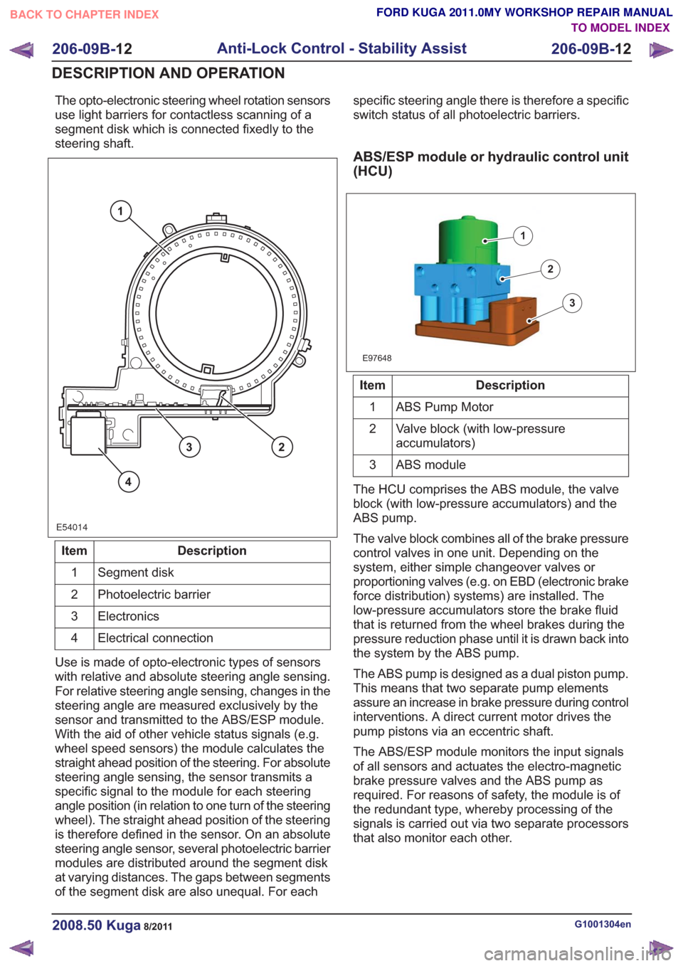
The opto-electronic steering wheel rotation sensors
use light barriers for contactless scanning of a
segment disk which is connected fixedly to the
steering shaft.
E54014
1
23
4
Description
Item
Segment disk
1
Photoelectric barrier
2
Electronics
3
Electrical connection
4
Use is made of opto-electronic types of sensors
with relative and absolute steering angle sensing.
For relative steering angle sensing, changes in the
steering angle are measured exclusively by the
sensor and transmitted to the ABS/ESP module.
With the aid of other vehicle status signals (e.g.
wheel speed sensors) the module calculates the
straight ahead position of the steering. For absolute
steering angle sensing, the sensor transmits a
specific signal to the module for each steering
angle position (in relation to one turn of the steering
wheel). The straight ahead position of the steering
is therefore defined in the sensor. On an absolute
steering angle sensor, several photoelectric barrier
modules are distributed around the segment disk
at varying distances. The gaps between segments
of the segment disk are also unequal. For each specific steering angle there is therefore a specific
switch status of all photoelectric barriers.
ABS/ESP module or hydraulic control unit
(HCU)
E97648
1
2
3
Description
Item
ABS Pump Motor
1
Valve block (with low-pressure
accumulators)
2
ABS module
3
The HCU comprises the ABS module, the valve
block (with low-pressure accumulators) and the
ABS pump.
The valve block combines all of the brake pressure
control valves in one unit. Depending on the
system, either simple changeover valves or
proportioning valves (e.g. on EBD (electronic brake
force distribution) systems) are installed. The
low-pressure accumulators store the brake fluid
that is returned from the wheel brakes during the
pressure reduction phase until it is drawn back into
the system by the ABS pump.
The ABS pump is designed as a dual piston pump.
This means that two separate pump elements
assure an increase in brake pressure during control
interventions. A direct current motor drives the
pump pistons via an eccentric shaft.
The ABS/ESP module monitors the input signals
of all sensors and actuates the electro-magnetic
brake pressure valves and the ABS pump as
required. For reasons of safety, the module is of
the redundant type, whereby processing of the
signals is carried out via two separate processors
that also monitor each other.
G1001304en2008.50 Kuga8/2011
206-09B- 12
Anti-Lock Control - Stability Assist
206-09B- 12
DESCRIPTION AND OPERATION
TO MODEL INDEX
BACK TO CHAPTER INDEX
FORD KUGA 2011.0MY WORKSHOP REPAIR MANUAL
Page 1700 of 2057
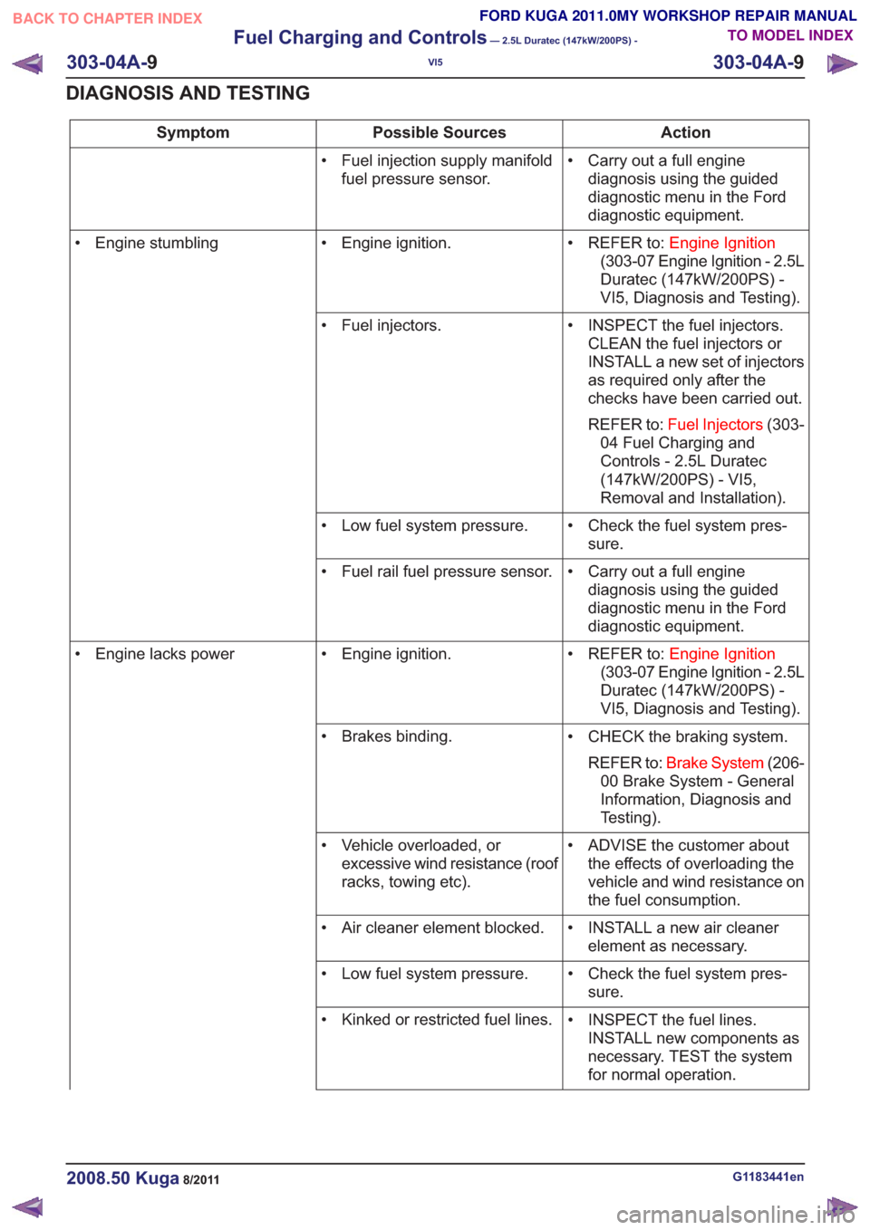
Action
Possible Sources
Symptom
• Carry out a full enginediagnosis using the guided
diagnostic menu in the Ford
diagnostic equipment.
• Fuel injection supply manifold
fuel pressure sensor.
• REFER to:Engine Ignition
(303-07 Engine Ignition - 2.5L
Duratec (147kW/200PS) -
VI5, Diagnosis and Testing).
• Engine ignition.
• Engine stumbling
• INSPECT the fuel injectors.CLEAN the fuel injectors or
INSTALL a new set of injectors
as required only after the
checks have been carried out.
REFER to: Fuel Injectors (303-
04 Fuel Charging and
Controls - 2.5L Duratec
(147kW/200PS) - VI5,
Removal and Installation).
• Fuel injectors.
• Check the fuel system pres-sure.
• Low fuel system pressure.
• Carry out a full enginediagnosis using the guided
diagnostic menu in the Ford
diagnostic equipment.
• Fuel rail fuel pressure sensor.
• REFER to:Engine Ignition
(303-07 Engine Ignition - 2.5L
Duratec (147kW/200PS) -
VI5, Diagnosis and Testing).
• Engine ignition.
• Engine lacks power
• CHECK the braking system.REFER to: Brake System (206-
00 Brake System - General
Information, Diagnosis and
Testing).
• Brakes binding.
• ADVISE the customer aboutthe effects of overloading the
vehicle and wind resistance on
the fuel consumption.
• Vehicle overloaded, or
excessive wind resistance (roof
racks, towing etc).
• INSTALL a new air cleanerelement as necessary.
• Air cleaner element blocked.
• Check the fuel system pres-sure.
• Low fuel system pressure.
• INSPECT the fuel lines.INSTALL new components as
necessary. TEST the system
for normal operation.
• Kinked or restricted fuel lines.
G1183441en2008.50 Kuga8/2011
303-04A-
9
Fuel Charging and Controls
— 2.5L Duratec (147kW/200PS) -
VI5
303-04A- 9
DIAGNOSIS AND TESTING
TO MODEL INDEX
BACK TO CHAPTER INDEX
FORD KUGA 2011.0MY WORKSHOP REPAIR MANUAL
Page 1710 of 2057
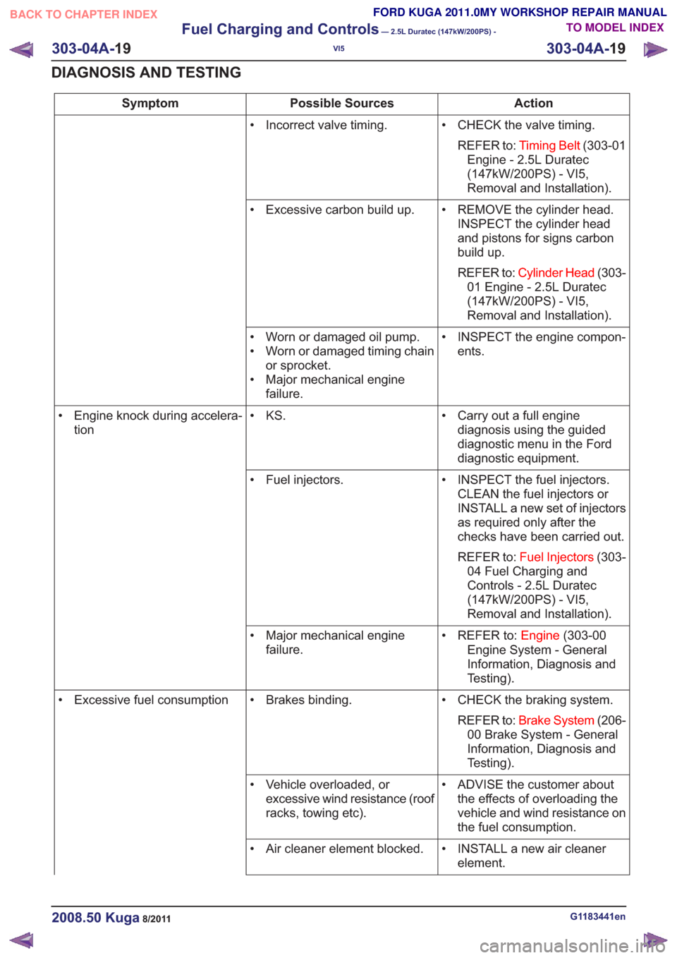
Action
Possible Sources
Symptom
• CHECK the valve timing.REFER to: Timing Belt (303-01
Engine - 2.5L Duratec
(147kW/200PS) - VI5,
Removal and Installation).
• Incorrect valve timing.
• REMOVE the cylinder head.INSPECT the cylinder head
and pistons for signs carbon
build up.
REFER to: Cylinder Head (303-
01 Engine - 2.5L Duratec
(147kW/200PS) - VI5,
Removal and Installation).
• Excessive carbon build up.
• INSPECT the engine compon-ents.
• Worn or damaged oil pump.
• Worn or damaged timing chain
or sprocket.
• Major mechanical engine failure.
• Carry out a full enginediagnosis using the guided
diagnostic menu in the Ford
diagnostic equipment.
• KS.
• Engine knock during accelera-
tion
• INSPECT the fuel injectors.CLEAN the fuel injectors or
INSTALL a new set of injectors
as required only after the
checks have been carried out.
REFER to: Fuel Injectors (303-
04 Fuel Charging and
Controls - 2.5L Duratec
(147kW/200PS) - VI5,
Removal and Installation).
• Fuel injectors.
• REFER to:Engine(303-00
Engine System - General
Information, Diagnosis and
Testing).
• Major mechanical engine
failure.
• CHECK the braking system.REFER to: Brake System (206-
00 Brake System - General
Information, Diagnosis and
Testing).
• Brakes binding.
• Excessive fuel consumption
• ADVISE the customer aboutthe effects of overloading the
vehicle and wind resistance on
the fuel consumption.
• Vehicle overloaded, or
excessive wind resistance (roof
racks, towing etc).
• INSTALL a new air cleanerelement.
• Air cleaner element blocked.
G1183441en2008.50 Kuga8/2011
303-04A-
19
Fuel Charging and Controls
— 2.5L Duratec (147kW/200PS) -
VI5
303-04A- 19
DIAGNOSIS AND TESTING
TO MODEL INDEX
BACK TO CHAPTER INDEX
FORD KUGA 2011.0MY WORKSHOP REPAIR MANUAL
Page 1822 of 2057
SECTION 307-01 Automatic Transmission/Transaxle
— Vehicles With: 5-Speed Automatic Transaxle - AW55 AWD
VEHICLE APPLICATION:2008.50 Kuga
PA G E
CONTENTS
SPECIFICATIONS
307-01-4
Specifications ........................................................................\
..............................................
DESCRIPTION AND OPERATION 307-01-5
Transmission Description (Component Location) ...............................................................
307-01-6
Transmission Description (Overview) ........................................................................\
.........
307-01-6
Components of the AW55 automatic transaxle ..................................................................
307-01-6
General overview ........................................................................\
....................................
307-01-8
Transaxle cooling ........................................................................\
....................................
307-01-8
External shift mechanism ........................................................................\
........................
307-01-9
Components of the electronic control ........................................................................\
.....
307-01-11
Overview of the brakes, clutches and one-way clutches ................................................
307-01-12
Input and output signals at the TCM ........................................................................\
.......
307-01-14
Knowing and Understanding Customer Concerns ..........................................................
307-01-14
Testing Possible Causes of Transmission Control Faults ...............................................
307-01-14
IDS Diagnosis ........................................................................\
.........................................
307-01-14
visual inspection ........................................................................\
.....................................
307-01-15
Towing the vehicle ........................................................................\
..................................
307-01-15
Push-starting the Vehicle ........................................................................\
........................
307-01-15
Jump-starting the Vehicle ........................................................................\
.......................
307-01-15
Selector Lever Emergency Release ........................................................................\
.......
307-01-16
Adjusting the Selector Lever Cable ........................................................................\
........
307-01-17
Transmission Fluid Level Check ........................................................................\
.............
307-01-17
Changing the Transmission Fluid ........................................................................\
...........
307-01-18
Diagnosis with IDS ........................................................................\
..................................
307-01-19
Resetting the counter for fluid change intervals. .............................................................
307-01-19
Programming the 'N' position of the TR sensor..............................................................
307-01-19
Resetting the values learned by the TCM .......................................................................
307-01-21
Transmission Description (System Operation and Component Description) .....................
307-01-21
System Operation ........................................................................\
.......................................
307-01-22
Functionality overview ........................................................................\
............................
307-01-24
Electronic Control System ........................................................................\
......................
307-01-24
Hydraulic Control System ........................................................................\
.......................
307-01-24
Type plate ........................................................................\
...............................................
307-01-25
Serial number of the transmission ........................................................................\
..........
307-01-25
Markings on the TCM ........................................................................\
.............................
307-01-25
Serial
number of the TCM ........................................................................\
.......................
307-01-25
Transmission Control ........................................................................\
..............................
307-01-27
Pin assignment for TCM connector 'C' (connection to transaxle) ...................................
307-01-28
Operation ........................................................................\
................................................
307-01-29
Gearshift control ........................................................................\
......................................
307-01-29
Adaptation ........................................................................\
...............................................
307-01-29
Shifting from 'P' to another transmission range ..............................................................
307-01-1
Automatic Transmission/Transaxle
— Vehicles With:
5-Speed Automatic Transaxle - AW55 AWD
307-01- 1
.
TO MODEL INDEX
BACK TO CHAPTER INDEX
PAGE 1 OF 3 FORD KUGA 2011.0MY WORKSHOP REPAIR MANUAL
Page 1823 of 2057
307-01-29
Automatic transmission, selector lever in position "D". ...................................................
307-01-29
Sport mode, selector lever in position "S" .......................................................................
307-01-29
Changing gear in select-shift mode........................................................................\
........
307-01-30
Selector lever from 'N' to 'R' position ........................................................................\
......
307-01-30
Self-test and Diagnosis ........................................................................\
...........................
307-01-30
Temperature controlled torque converter lockup ............................................................
307-01-30
Slip locking ........................................................................\
..............................................
307-01-30
Hill climbing ........................................................................\
.............................................
307-01-31
Downhill driving ........................................................................\
.......................................
307-01-31
Hill-hold function ........................................................................\
.....................................
307-01-31
Altitude correction ........................................................................\
...................................
307-01-31
Selector lever lock ........................................................................\
..................................
307-01-31
Shifting from P into another transmission range .............................................................
307-01-31
Shifting from N into another transmission range .............................................................
307-01-31
Power flow through the transmission ........................................................................\
......
307-01-31
Clutches and brakes ........................................................................\
...............................
307-01-33
Position P (park) ........................................................................\
.....................................
307-01-34
Position N (neutral) ........................................................................\
.................................
307-01-35
Position D, 1st gear........................................................................\
................................
307-01-36
Position D, 2nd gear ........................................................................\
...............................
307-01-37
Position D, 3rd gear ........................................................................\
................................
307-01-38
Position D, 4th gear ........................................................................\
................................
307-01-39
Position D, 5th gear ........................................................................\
................................
307-01-40
Position R (reverse) ........................................................................\
................................
307-01-41
Service instructions ........................................................................\
.................................
307-01-41
Towing procedure ........................................................................\
...................................
307-01-42
Reset adaptation data ........................................................................\
.............................
307-01-42
Limp home mode ........................................................................\
....................................
307-01-42
Component Description ........................................................................\
..............................
Tasks of the electronic components ........................................................................\
........
307-01-44
Input signals ........................................................................\
............................................
307-01-45
Output signals ........................................................................\
.........................................
Control valve assembly ........................................................................\
...........................
Shift solenoids S1 - S5 ........................................................................\
...........................
PWM-
solenoid valve – TCC (SLU) ........................................................................\
........
PWM solenoid valve – shift pressure (SLS) ...................................................................
PWM solenoid valve for main line pressure (SLT) ..........................................................
307-01-52
Installation position ........................................................................\
.................................
Operation ........................................................................\
................................................
Selector lever with integrated select-shift switch module ...............................................
Oil pump ........................................................................\
..................................................
Torque converter with TCC ........................................................................\
.....................
The TSS sensor ........................................................................\
......................................
The OSS sensor ........................................................................\
.....................................
The TFT sensor ........................................................................\
......................................
The TR sensor ........................................................................\
........................................
GENERAL PROCEDURES
T ransmission Fluid Level Check ........................................................................\
.................
307-01-63
T ransmission Fluid Drain and Refill ........................................................................\
............
REMOVAL AND INSTALLATION 307-01-67
Halfshaft Seal LH ........................................................................\
........................................
307-01-68
Halfshaft Seal RH........................................................................\
.......................................
307-01-69
Main Control Valve Body ........................................................................\
............................
307-01-2
Automatic Transmission/Transaxle
— Vehicles With:
5-Speed Automatic Transaxle - AW55 AWD
307-01- 2
.
TO MODEL INDEX
BACK TO CHAPTER INDEX
307-01-42
307-01-49
307-01-52 307-01-47
307-01-45
307-01-50
307-01-51
307-01-53
307-01-55
307-01-54
307-01-56
307-01-57
307-01-58
307-01-61 307-01-60
PAGE 2 OF 3 FORD KUGA 2011.0MY WORKSHOP REPAIR MANUAL
Page 1828 of 2057
E125525
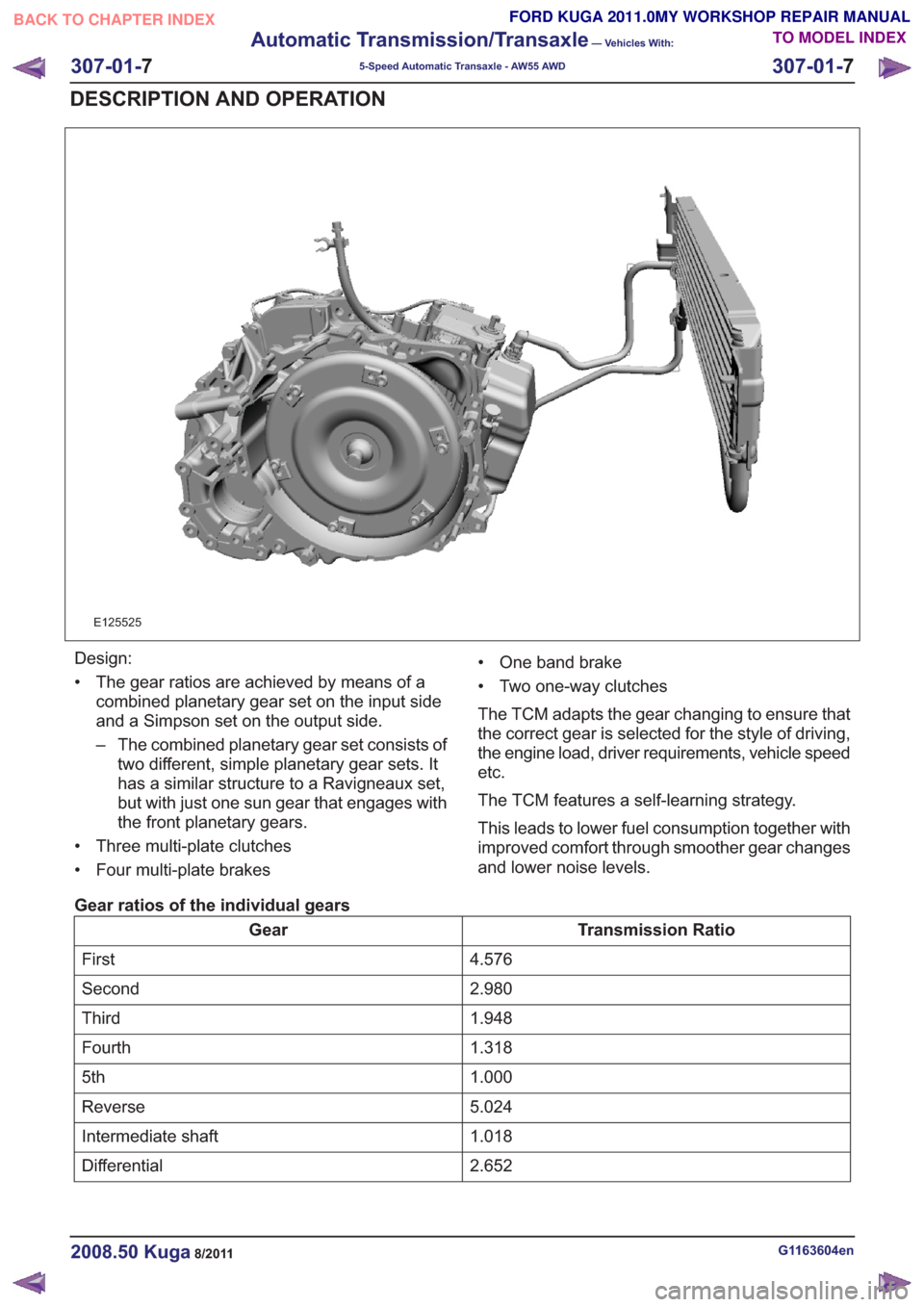
Design:
• The gear ratios are achieved by means of acombined planetary gear set on the input side
and a Simpson set on the output side.
– The combined planetary gear set consists oftwo different, simple planetary gear sets. It
has a similar structure to a Ravigneaux set,
but with just one sun gear that engages with
the front planetary gears.
• Three multi-plate clutches
• Four multi-plate brakes • One band brake
• Two one-way clutches
The TCM adapts the gear changing to ensure that
the correct gear is selected for the style of driving,
the engine load, driver requirements, vehicle speed
etc.
The TCM features a self-learning strategy.
This leads to lower fuel consumption together with
improved comfort through smoother gear changes
and lower noise levels.
Gear ratios of the individual gears
Transmission Ratio
Gear
4.576
First
2.980
Second
1.948
Third
1.318
Fourth
1.000
5th
5.024
Reverse
1.018
Intermediate shaft
2.652
Differential
G1163604en2008.50 Kuga8/2011
307-01- 7
Automatic Transmission/Transaxle
— Vehicles With:
5-Speed Automatic Transaxle - AW55 AWD
307-01- 7
DESCRIPTION AND OPERATION
TO MODEL INDEX
BACK TO CHAPTER INDEX
FORD KUGA 2011.0MY WORKSHOP REPAIR MANUAL
Page 1831 of 2057
E112323
1
2
7
6
4
5
3
10
9
11
12
Description
Item
The TSS sensor
1
The OSS sensor
2
PWM (pulse width modulation)- solenoid
valve – TCC (torque converter clutch)
(SLU)
3
PWM solenoid valve – shift pressure (SLS)
4
Shift solenoid S1
5
Shift solenoid S4
6Description
Item
Shift solenoid S3
7
Shift solenoid S5
8
Shift solenoid S2
9
The TFT (transmission fluid temperature)
sensor
10
PWM solenoid valve for main line pressure
(SLT)
11
TCM with integrated TR sensor
12
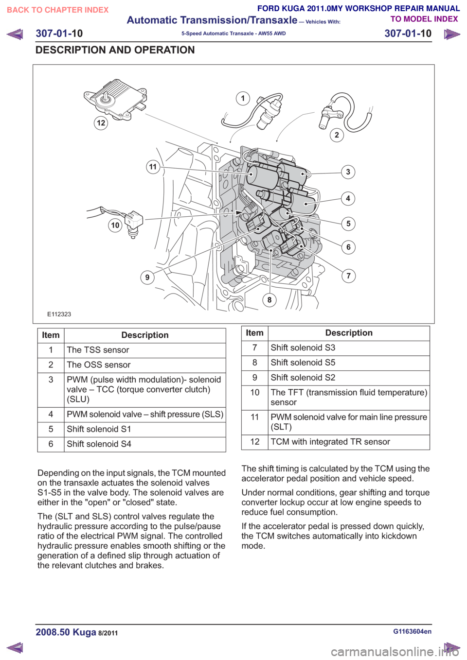
Depending on the input signals, the TCM mounted
on the transaxle actuates the solenoid valves
S1-S5 in the valve body. The solenoid valves are
either in the "open" or "closed" state.
The (SLT and SLS) control valves regulate the
hydraulic pressure according to the pulse/pause
ratio of the electrical PWM signal. The controlled
hydraulic pressure enables smooth shifting or the
generation of a defined slip through actuation of
the relevant clutches and brakes. The shift timing is calculated by the TCM using the
accelerator pedal position and vehicle speed.
Under normal conditions, gear shifting and torque
converter lockup occur at low engine speeds to
reduce fuel consumption.
If the accelerator pedal is pressed down quickly,
the TCM switches automatically into kickdown
mode.
G1163604en2008.50 Kuga8/2011
307-01-
10
Automatic Transmission/Transaxle
— Vehicles With:
5-Speed Automatic Transaxle - AW55 AWD
307-01- 10
DESCRIPTION AND OPERATION
TO MODEL INDEX
BACK TO CHAPTER INDEX
FORD KUGA 2011.0MY WORKSHOP REPAIR MANUAL