2011 FORD KUGA four wheel drive
[x] Cancel search: four wheel drivePage 81 of 2057

Noise, Vibration and Harshness (NVH)
Inspection and Verification
1. Verify the customer concern.
2. Visually inspect for obvious signs of mechanicalor electrical damage.
3. If an obvious cause for an observed or reported concern is found, correct the cause (if possible)
before proceeding to the next step.
4. If the concern is not visually evident, verify the symptom and REFER to the Symptom Chart.
How to Use this Diagnostic Procedure
Section
• Noise, vibration and harshness (NVH) concernshave become more important as vehicles have
become more sensitive to these vibrations. This
section is designed to aid in identifying these
concerns.
• The section provides diagnostic procedures based on symptom. If the condition occurs at
high speed, for instance, the most likely place
to start is under Shake and Vibration While
Driving.
• The road test procedure will tell how to sort the conditions into categories and how to tell a
vibration from a shake.
• A series of Road Test Quick Checks are provided to make sure that a cause is either
pinpointed or eliminated.
• Name the condition, proceed to the appropriate section and locate the correct diagnosis. When
the condition is identified, the job is partly done.
• Follow the diagnostic procedure as outlined.
• Quick Checks are described within the step, while more involved tests and adjustments are
outlined in General Procedures.
• Always follow each step exactly and make notes to recall important findings later.
Customer Interview
The road test and customer interview (if available)
provide information that will help identify the
concern and will provide direction to the correct
starting point for diagnosis.
Identify the Condition
NVH usually occur in four areas:
• tires
• engine accessories
• suspension
• driveline
It is important, therefore, that an NVH concern be
isolated into its specific area(s) as soon as
possible. The easiest and quickest way to do this
is to carry out the Road Test as outlined. To assist
in the diagnosis and testing procedure(s), use a
suitable approved NVH diagnosis tester.
Noise Diagnostic Procedure
Non-Axle Noise
The five most common sources of non-axle noise
are exhaust, tires, roof racks, trim panels and
transmission.
Therefore, make sure that none of the following
conditions are the cause of the noise before
proceeding with a driveline teardown and
diagnosis.
• In certain conditions, the pitch of the exhaustmay sound very much like gear noise. At other
times, it can be mistaken for a wheel bearing
rumble.
• Tires, especially snow tires, can have a high pitched tread whine or roar, similar to gear
noise. Radial tires may have this characteristic.
Also, any non-standard tire with an unusual
tread construction may emit a roar or whine
noise.
• Trim panels can also cause whistling or whining noise.
• Clunk may be a metallic noise heard when the automatic transaxle is engaged in "R"
(REVERSE) or "D" (DRIVE) or it may occur
when the throttle is applied or released. It is
caused by backlash somewhere in the driveline.
• Bearing rumble sounds like marbles being tumbled. This condition is usually caused by a
damaged wheel bearing.
G37349en2008.50 Kuga8/2011
100-04- 2
Noise, Vibration and Harshness
100-04- 2
DIAGNOSIS AND TESTING
TO MODEL INDEX
BACK TO CHAPTER INDEX
FORD KUGA 2011.0MY WORKSHOP REPAIR MANUAL
Page 304 of 2057

Description
Item
In-car entertainment
1
Genetic electronic module (GEM).
2
instrument cluster
3
ABS4
ABS sensor assembly
5
Rear LH mid/bass range speaker
6
Rear RH mid/bass range speaker
7
Rear LH tweeter
8 Description
Item
Rear RH tweeter
9
AUX port
10
Radio remote control.
11
FM/AM antenna
12
Front LH mid/bass speaker
13
Front RH mid/bass speaker
14
Front LH tweeter
15
Front RH tweeter
16
System Operation
In-car entertainment
The audio system is connected to the MS CAN
network and uses an internal amplifier which
directly drives the system speakers. It can only be
operated via the head unit and the radio remote
control. The head unit is connected to the vehicle
on the medium speed CAN bus. This allows the
unit to be interrogated for diagnostic purposes.
The automatic volume control (AVC) adjusts the
audio volume depending on the driving speed. The
audio device receives the necessary signals for
the ABS (anti-lock brake system) wheel sensors
from the instrument cluster on the MS-CAN. As
vehicle speed increases the audio level is adjusted
to compensate for extra road and vehicle noise.
Eight AVC settings are possible.
To choose the setting for automatic volume control,
press the MENU button until the AVC display
appears.
The required adjustment level is determined by the
Infotainment control unit based on the driving
speed signal. The vehicle speed signal is received
over the CAN. The signal is an average of the four
wheel speed sensor signals. Should an invalid
speed signal be received the AVC will not alter the
output volume.
AVC is controlled by the audio amplifier. Component Description
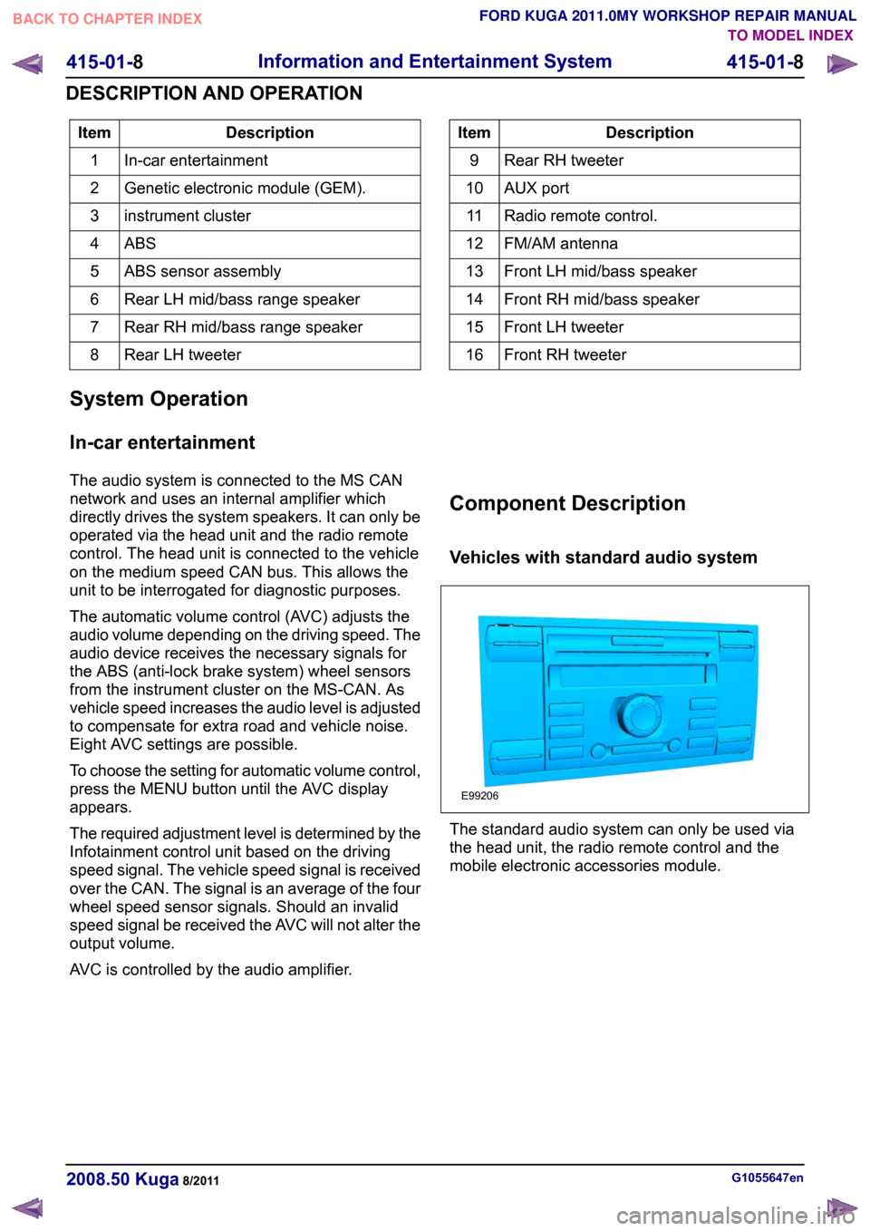
Vehicles with standard audio system
The standard audio system can only be used via
the head unit, the radio remote control and the
mobile electronic accessories module.
G1055647en
2008.50 Kuga 8/2011 415-01-8
Information and Entertainment System
415-01-8
DESCRIPTION AND OPERATIONTO MODEL INDEX
BACK TO CHAPTER INDEX
FORD KUGA 2011.0MY WORKSHOP REPAIR MANUALE99206
Page 1251 of 2057

Rear Drive Axle and Differential – System Operation andComponent Description
System Operation
General Information
The powertrain with all-wheel drive consists of the
following main components:
• engine
• transaxle with front axle differential
• transfer box
• halfshafts and driveshafts
• Haldex clutch
• rear axle differential
The Haldex clutch guarantees continuous variable
torque transmission to the rear axle under all
driving conditions. The Haldex clutch reacts
immediately and equally quickly with slow or fast
wheel slip.
A difference in angle of rotation of 90° between the
input and output shafts is required to build up
maximum pressure at the multi-plate clutch or to
transmit maximum torque.
The advantage of vehicles with all-wheel drive is
that they distribute the drive between all four
wheels. They therefore have a higher tractive
power. They feature improved cornering behaviour,
as the grip at all four wheels can be better utilised.
Thus, the wheels contribute to a greater degree
towards cornering stability.
The engine torque is transmitted from the transfer
box to the rear axle via a driveshaft. The driveshaft
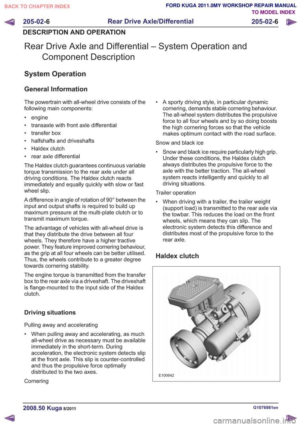
is flange-mounted to the input side of the Haldex
clutch.
Driving situations
Pulling away and accelerating
• When pulling away and accelerating, as muchall-wheel drive as necessary must be available
immediately in the short-term. During
acceleration, the electronic system detects slip
at the front axle. This slip is counter-controlled
and thus the propulsive force optimally
distributed to the two axes.
Cornering • A sporty driving style, in particular dynamic
cornering, demands stable cornering behaviour.
The all-wheel system distributes the propulsive
force to all four wheels and by so doing boosts
the high cornering forces so that the vehicle
makes optimum contact with the road surface.
Snow and black ice
• Snow and black ice require particularly high grip. Under these conditions, the Haldex clutch
always distributes the propulsive force to the
axle with the better traction. The all-wheel
system reacts intelligently and quickly to all
driving situations.
Trailer operation
• When driving with a trailer, the trailer weight (support load) is transmitted to the rear axle via
the towbar. This reduces the load on the front
wheels, which means they can slip. The
electronic system detects this difference and
distributes most of the propulsive force to the
rear axle.
Haldex clutch
E100642
G1076981en2008.50 Kuga8/2011
205-02- 6
Rear Drive Axle/Differential
205-02- 6
DESCRIPTION AND OPERATION
TO MODEL INDEX
BACK TO CHAPTER INDEX
FORD KUGA 2011.0MY WORKSHOP REPAIR MANUAL