2011 FORD KUGA warning
[x] Cancel search: warningPage 1315 of 2057
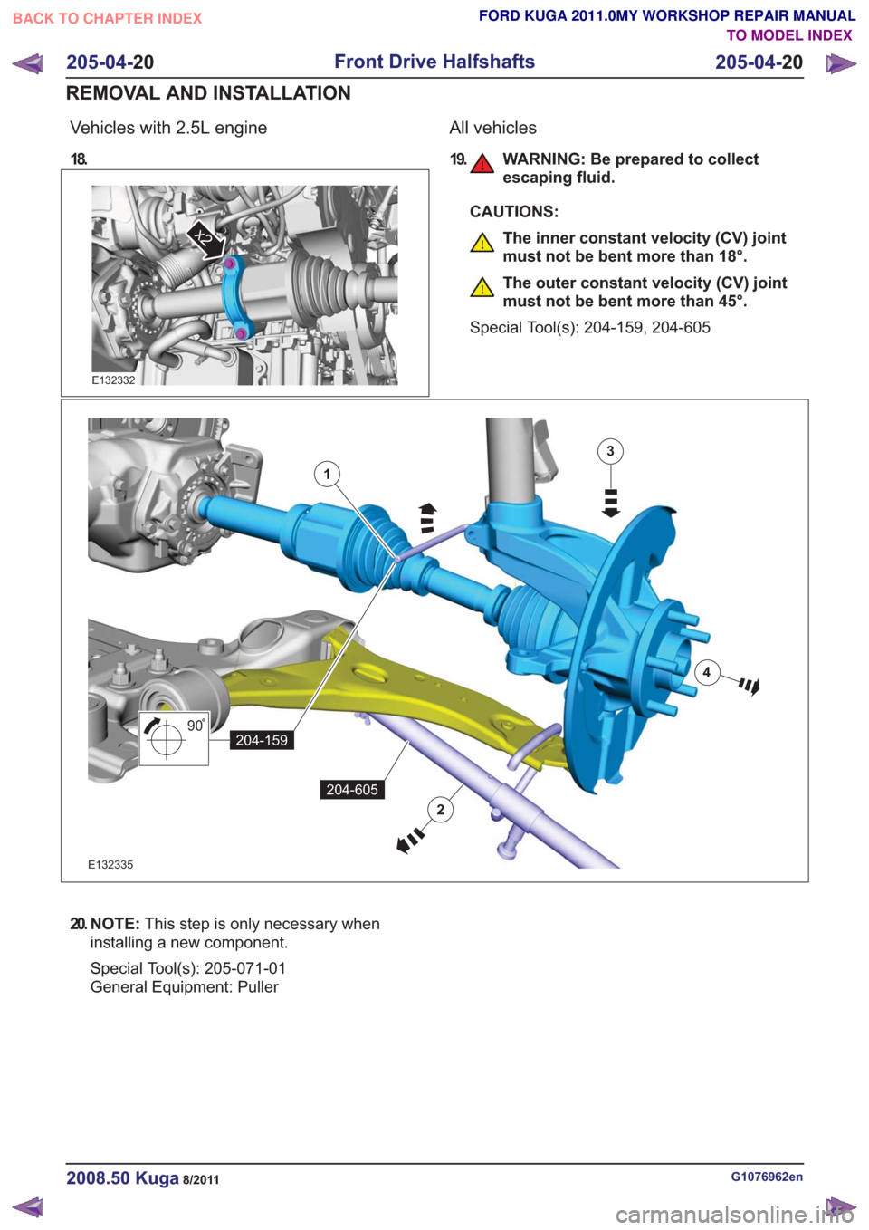
Vehicles with 2.5L engine
18.
x2x2
E132332
All vehicles
19. WARNING: Be prepared to collectescaping fluid.
CAUTIONS:
The inner constant velocity (CV) joint
must not be bent more than 18°.
The outer constant velocity (CV) joint
must not be bent more than 45°.
Special Tool(s): 204-159, 204-605
90
204-159
3
4
1
204-605
2
90
204-159
3
4
1
204-605
2
E132335
20. N O T E : This step is only necessary when
installing a new component.
Special Tool(s): 205-071-01
General Equipment: Puller
G1076962en2008.50 Kuga8/2011
205-04- 20
Front Drive Halfshafts
205-04- 20
REMOVAL AND INSTALLATION
TO MODEL INDEX
BACK TO CHAPTER INDEX
FORD KUGA 2011.0MY WORKSHOP REPAIR MANUAL
Page 1319 of 2057
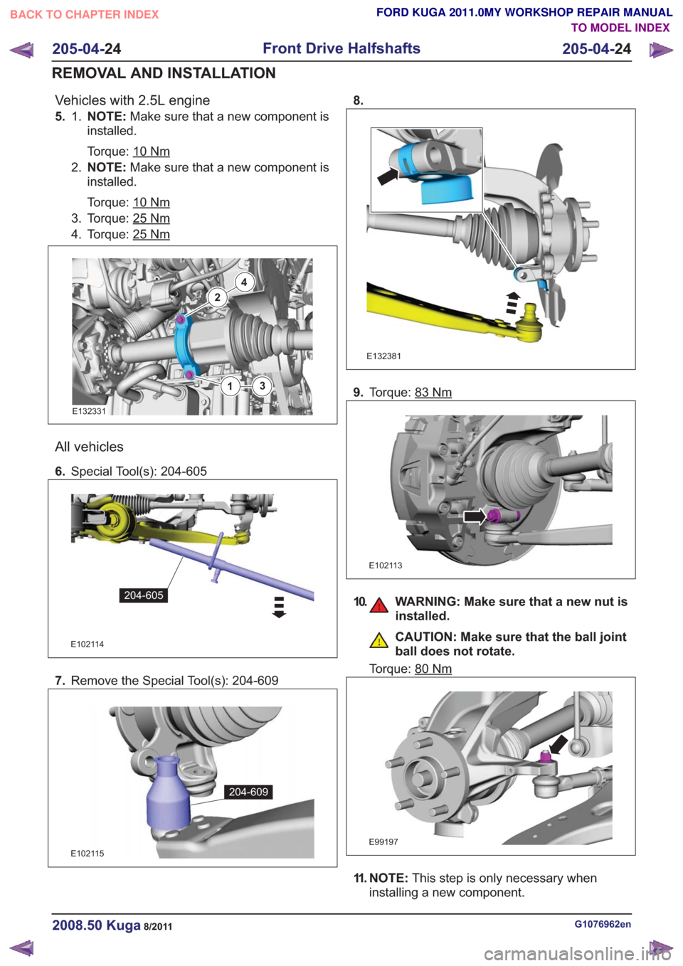
Vehicles with 2.5L engine
5. NOTE:Make sure that a new component is
installed.
Torque: 10
Nm
1.
2. NOTE: Make sure that a new component is
installed.
Torque: 10
Nm
3. Torque: 25Nm
4. Torque: 25Nm
2
4
13
2
4
13
E132331
All vehicles
6. Special Tool(s): 204-605
E102114
204-605
7.Remove the Special Tool(s): 204-609
E102115
204-609
8.
E132381
9.Torque: 83Nm
E102113
10. WARNING: Make sure that a new nut is
installed.
CAUTION: Make sure that the ball joint
ball does not rotate.
Torque: 80
Nm
E99197
11. NOTE: This step is only necessary when
installing a new component.
G1076962en2008.50 Kuga8/2011
205-04- 24
Front Drive Halfshafts
205-04- 24
REMOVAL AND INSTALLATION
TO MODEL INDEX
BACK TO CHAPTER INDEX
FORD KUGA 2011.0MY WORKSHOP REPAIR MANUAL
Page 1330 of 2057
Rear Halfshaft
Special Tool(s) / General Equipment308-759
Remover, Rear Driveshaft
E100143
Cable Ties
Special Tool(s) / General EquipmentTire Lever
Transmission Jack
Materials
Specification
Name
WSK-M2G349-A8 /
9U7J-M2G349-AA
Sealant LGN
Removal
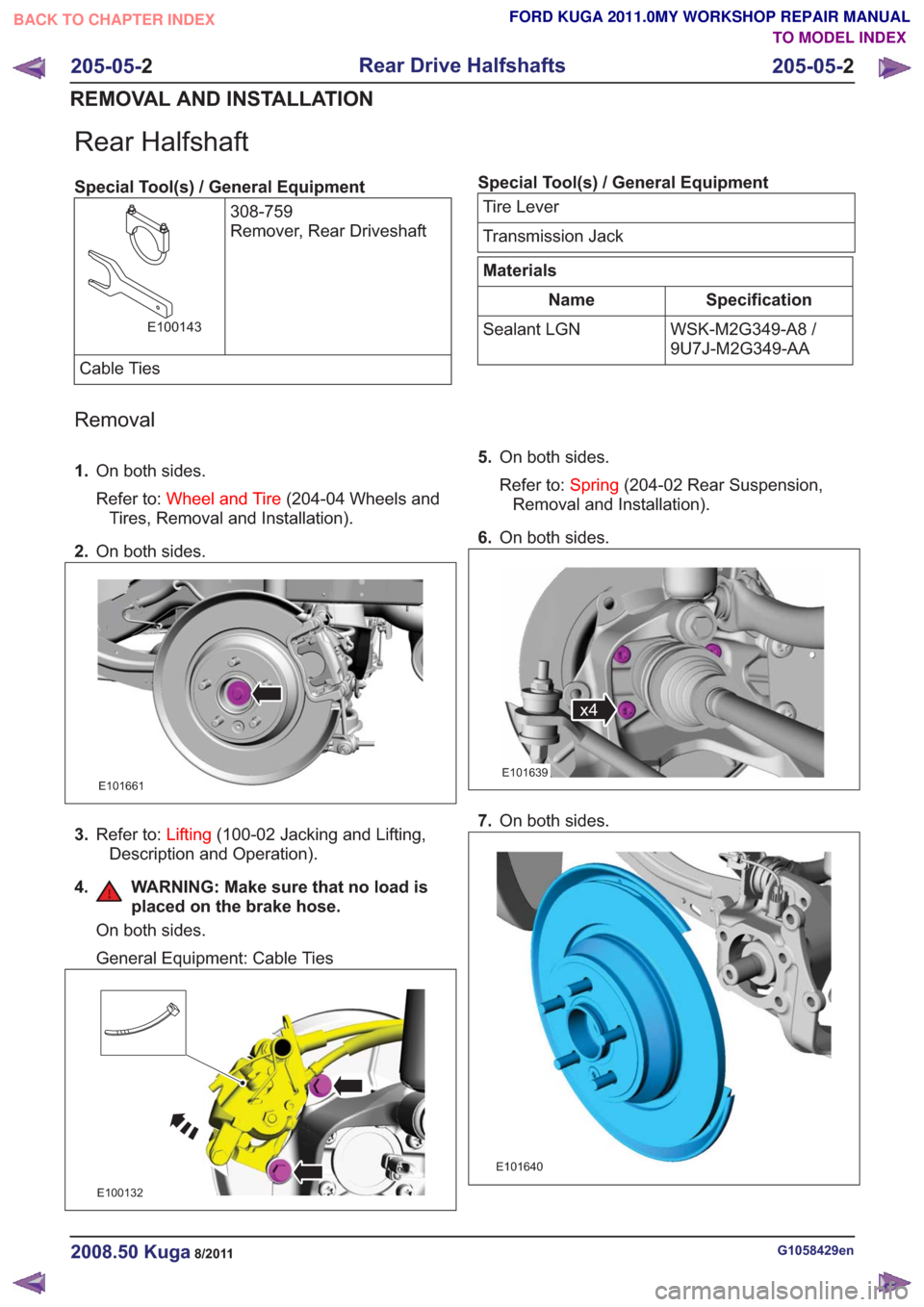
1.
On both sides.
Refer to: Wheel and Tire (204-04 Wheels and
Tires, Removal and Installation).
2. On both sides.
E101661
3.Refer to: Lifting(100-02 Jacking and Lifting,
Description and Operation).
4. WARNING: Make sure that no load is placed on the brake hose.
On both sides.
General Equipment: Cable Ties
E100132
5.On both sides.
Refer to: Spring(204-02 Rear Suspension,
Removal and Installation).
6. On both sides.
x4x4
E101639
7.On both sides.
E101640
G1058429en2008.50 Kuga8/2011
205-05- 2
Rear Drive Halfshafts
205-05- 2
REMOVAL AND INSTALLATION
TO MODEL INDEX
BACK TO CHAPTER INDEX
FORD KUGA 2011.0MY WORKSHOP REPAIR MANUAL
Page 1335 of 2057
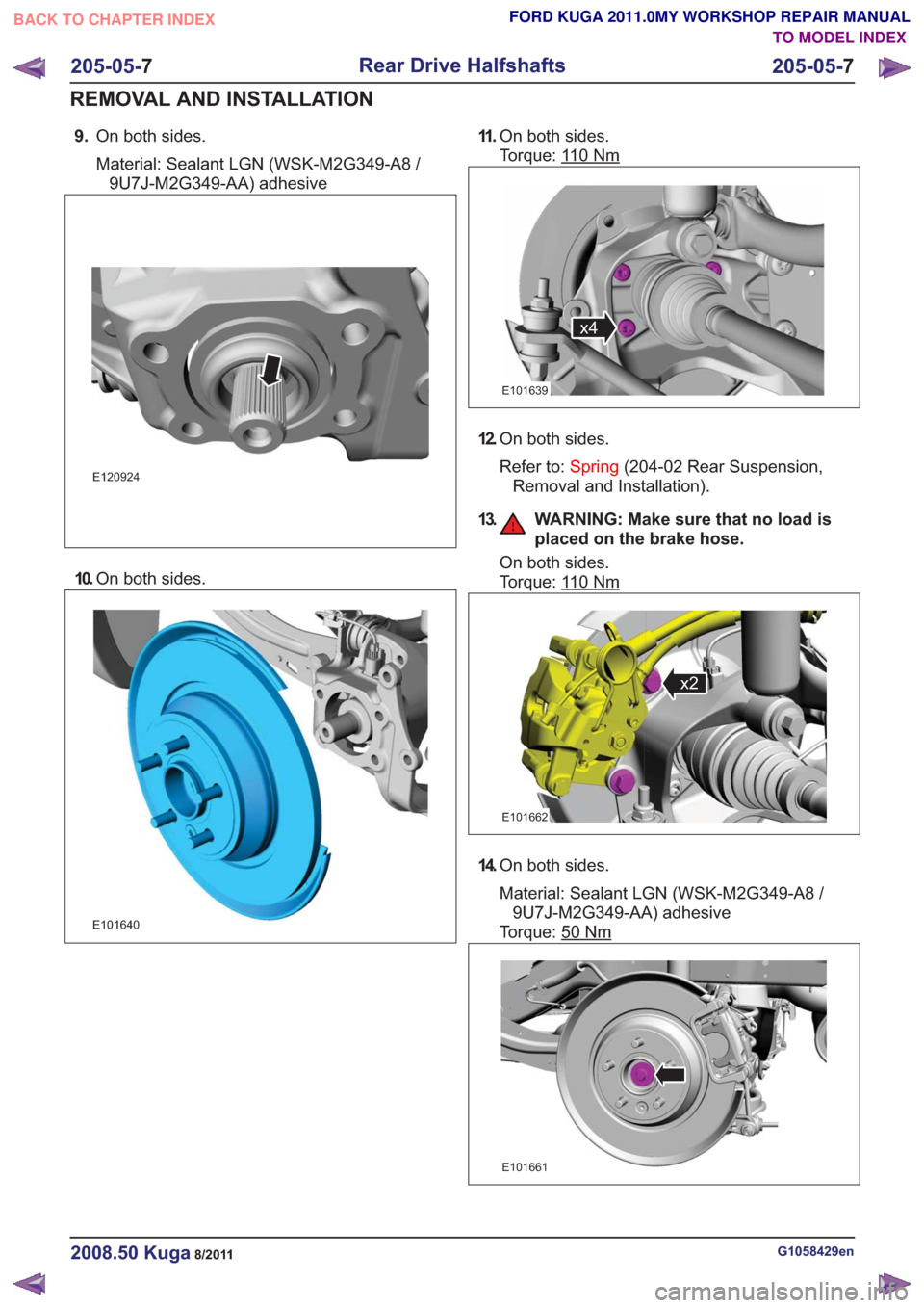
9.On both sides.
Material: Sealant LGN (WSK-M2G349-A8 /
9U7J-M2G349-AA) adhesive
E120924
10. On both sides.
E101640
11 .On both sides.
Torque: 1
10Nm
x4x4
E101639
12.On both sides.
Refer to: Spring(204-02 Rear Suspension,
Removal and Installation).
13. WARNING: Make sure that no load is placed on the brake hose.
On both sides.
Torque: 1
10Nm
x2x2
E101662
14.On both sides.
Material: Sealant LGN (WSK-M2G349-A8 /
9U7J-M2G349-AA) adhesive
Torque: 50
Nm
E101661
G1058429en2008.50 Kuga8/2011
205-05- 7
Rear Drive Halfshafts
205-05- 7
REMOVAL AND INSTALLATION
TO MODEL INDEX
BACK TO CHAPTER INDEX
FORD KUGA 2011.0MY WORKSHOP REPAIR MANUAL
Page 1340 of 2057
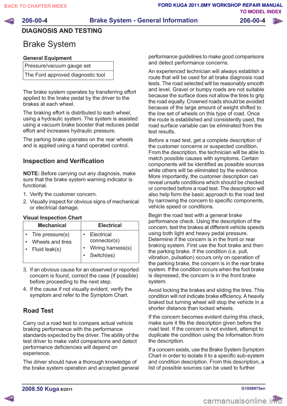
Brake System
General EquipmentPressure/vacuum gauge set
The Ford approved diagnostic tool
The brake system operates by transferring effort
applied to the brake pedal by the driver to the
brakes at each wheel.
The braking effort is distributed to each wheel,
using a hydraulic system. The system is assisted
using a vacuum brake booster that reduces pedal
effort and increases hydraulic pressure.
The parking brake operates on the rear wheels
and is applied using a hand operated control.
Inspection and Verification
NOTE: Before carrying out any diagnosis, make
sure that the brake system warning indicator is
functional.
1. Verify the customer concern.
2. Visually inspect for obvious signs of mechanical or electrical damage.
Visual Inspection Chart
Electrical
Mechanical
• Electricalconnector(s)
• Wiring harness(s)
• Switch(es)
• Tire pressure(s)
• Wheels and tires
• Fluid leak(s)
3. If an obvious cause for an observed or reported concern is found, correct the case (if possible)
before proceeding to the next step.
4. If the cause if not visually evident, verify the symptom and refer to the Symptom Chart.
Road Test
Carry out a road test to compare actual vehicle
braking performance with the performance
standards expected by the driver. The ability of the
test driver to make valid comparisons and detect
performance deficiencies will depend on
experience.
The driver should have a thorough knowledge of
the brake system operation and accepted general performance guidelines to make good comparisons
and detect performance concerns.
An experienced technician will always establish a
route that will be used for all brake diagnosis road
tests. The road selected will be reasonably smooth
and level. Gravel or bumpy roads are not suitable
because the surface does not allow the tires to grip
the road equally. Crowned roads should be avoided
because of the large amount of weight shifted to
the low set of wheels on this type of road. Once
the route is established and consistently used, the
road surface variable can be eliminated from the
test results.
Before a road test, get a complete description of
the customer concerns or suspected condition.
From the description, the technician will be able to
match possible causes with symptoms. Certain
components will be identified as possible sources
while others will be eliminated by the evidence.
More importantly, the customer description can
reveal unsafe conditions which should be checked
or corrected before a road test. The description will
also help form the basic approach to the road test
by narrowing the concern to specific components,
vehicle speed or conditions.
Begin the road test with a general brake
performance check. Using the description of the
concern, test the brakes at different vehicle speeds
using both light and heavy pedal pressure.
Determine if the concern is in the front or rear
braking system. First use the foot brake and then
the parking brake. If the condition (i.e. pull,
vibration, pulsation) occurs only on operation of
the parking brake, the concern is in the rear brake
system. If the condition occurs when the foot brake
is depressed, the concern is in the front brake
system.
Avoid locking the brakes and sliding the tires. This
condition will not indicate brake efficiency. A heavily
braked but turning wheel will stop the vehicle in a
shorter distance than locked wheels.
If the concern becomes evident during this check,
make sure it fits the description given before the
road test. If the concern is not evident, attempt to
duplicate the condition using the information from
the description.
If a concern exists, use the Brake System Symptom
Chart in order to isolate it to a specific sub-system
and condition description. From this description, a
list of possible sources can be used to further
G1058975en2008.50 Kuga8/2011
206-00-
4
Brake System - General Information
206-00- 4
DIAGNOSIS AND TESTING
TO MODEL INDEX
BACK TO CHAPTER INDEX
FORD KUGA 2011.0MY WORKSHOP REPAIR MANUAL
Page 1341 of 2057
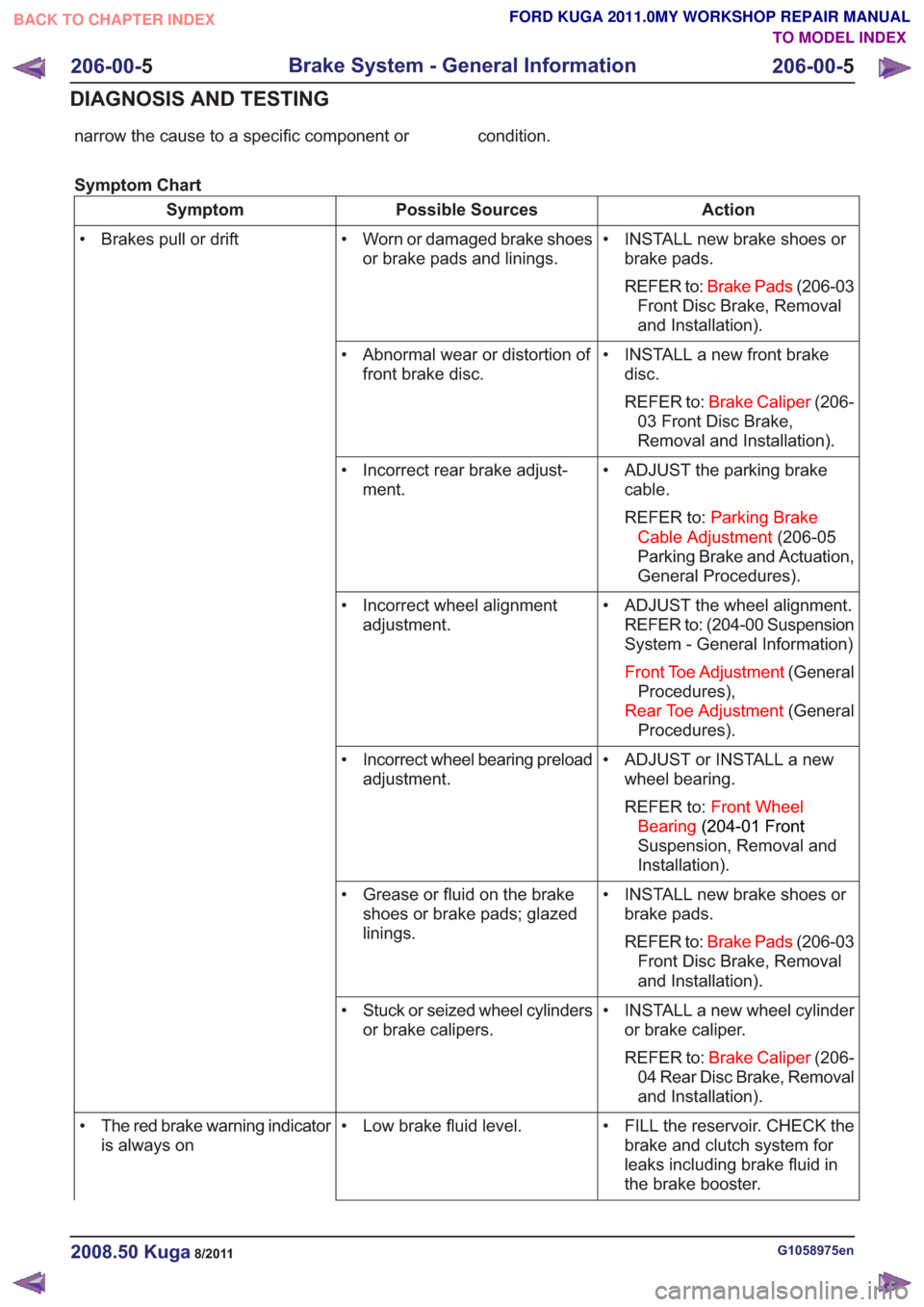
narrow the cause to a specific component or condition.
Symptom Chart
Action
Possible Sources
Symptom
• INSTALL new brake shoes orbrake pads.
REFER to: Brake Pads (206-03
Front Disc Brake, Removal
and Installation).
• Worn or damaged brake shoes
or brake pads and linings.
• Brakes pull or drift
• INSTALL a new front brakedisc.
REFER to: Brake Caliper (206-
03 Front Disc Brake,
Removal and Installation).
• Abnormal wear or distortion of
front brake disc.
• ADJUST the parking brakecable.
REFER to: Parking Brake
Cable Adjustment (206-05
Parking Brake and Actuation,
General Procedures).
• Incorrect rear brake adjust-
ment.
• ADJUST the wheel alignment.REFER to: (204-00 Suspension
System - General Information)
Front Toe Adjustment (General
Procedures),
Rear Toe Adjustment (General
Procedures).
• Incorrect wheel alignment
adjustment.
• ADJUST or INSTALL a newwheel bearing.
REFER to: Front Wheel
Bearing (204-01 Front
Suspension, Removal and
Installation).
• Incorrect wheel bearing preload
adjustment.
• INSTALL new brake shoes orbrake pads.
REFER to: Brake Pads (206-03
Front Disc Brake, Removal
and Installation).
• Grease or fluid on the brake
shoes or brake pads; glazed
linings.
• INSTALL a new wheel cylinderor brake caliper.
REFER to: Brake Caliper (206-
04 Rear Disc Brake, Removal
and Installation).
• Stuck or seized wheel cylinders
or brake calipers.
• FILL the reservoir. CHECK thebrake and clutch system for
leaks including brake fluid in
the brake booster.
• Low brake fluid level.
• The red brake warning indicator
is always on
G1058975en2008.50 Kuga8/2011
206-00- 5
Brake System - General Information
206-00- 5
DIAGNOSIS AND TESTING
TO MODEL INDEX
BACK TO CHAPTER INDEX
FORD KUGA 2011.0MY WORKSHOP REPAIR MANUAL
Page 1354 of 2057
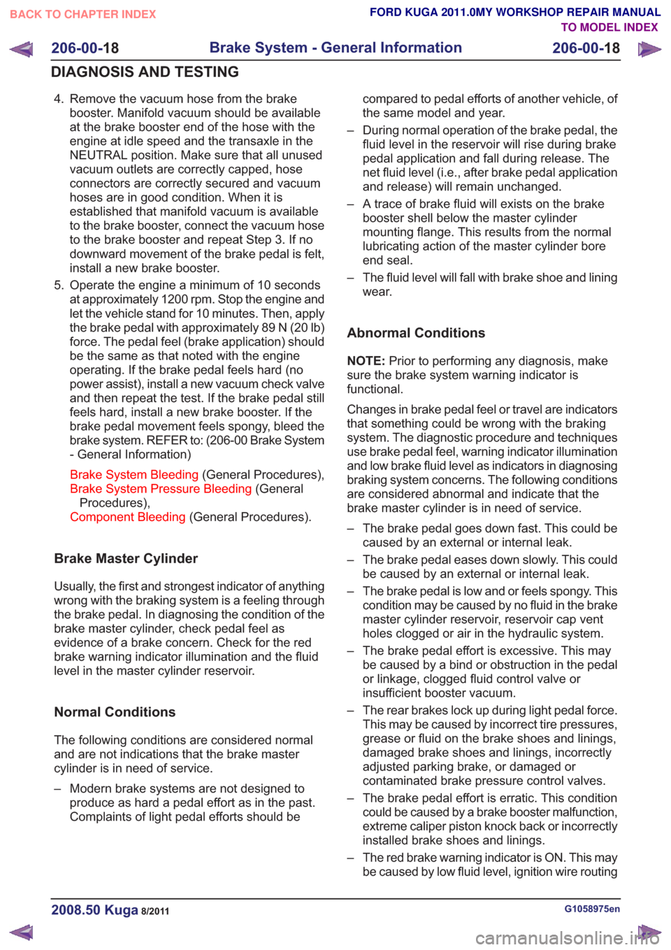
4. Remove the vacuum hose from the brakebooster. Manifold vacuum should be available
at the brake booster end of the hose with the
engine at idle speed and the transaxle in the
NEUTRAL position. Make sure that all unused
vacuum outlets are correctly capped, hose
connectors are correctly secured and vacuum
hoses are in good condition. When it is
established that manifold vacuum is available
to the brake booster, connect the vacuum hose
to the brake booster and repeat Step 3. If no
downward movement of the brake pedal is felt,
install a new brake booster.
5. Operate the engine a minimum of 10 seconds at approximately 1200 rpm. Stop the engine and
let the vehicle stand for 10 minutes. Then, apply
the brake pedal with approximately 89 N (20 lb)
force. The pedal feel (brake application) should
be the same as that noted with the engine
operating. If the brake pedal feels hard (no
power assist), install a new vacuum check valve
and then repeat the test. If the brake pedal still
feels hard, install a new brake booster. If the
brake pedal movement feels spongy, bleed the
brake system. REFER to: (206-00 Brake System
- General Information)
Brake System Bleeding (General Procedures),
Brake System Pressure Bleeding (General
Procedures),
Component Bleeding (General Procedures).
Brake Master Cylinder
Usually, the first and strongest indicator of anything
wrong with the braking system is a feeling through
the brake pedal. In diagnosing the condition of the
brake master cylinder, check pedal feel as
evidence of a brake concern. Check for the red
brake warning indicator illumination and the fluid
level in the master cylinder reservoir.
Normal Conditions
The following conditions are considered normal
and are not indications that the brake master
cylinder is in need of service.
– Modern brake systems are not designed to
produce as hard a pedal effort as in the past.
Complaints of light pedal efforts should be compared to pedal efforts of another vehicle, of
the same model and year.
– During normal operation of the brake pedal, the fluid level in the reservoir will rise during brake
pedal application and fall during release. The
net fluid level (i.e., after brake pedal application
and release) will remain unchanged.
– A trace of brake fluid will exists on the brake booster shell below the master cylinder
mounting flange. This results from the normal
lubricating action of the master cylinder bore
end seal.
– The fluid level will fall with brake shoe and lining wear.
Abnormal Conditions
NOTE: Prior to performing any diagnosis, make
sure the brake system warning indicator is
functional.
Changes in brake pedal feel or travel are indicators
that something could be wrong with the braking
system. The diagnostic procedure and techniques
use brake pedal feel, warning indicator illumination
and low brake fluid level as indicators in diagnosing
braking system concerns. The following conditions
are considered abnormal and indicate that the
brake master cylinder is in need of service.
– The brake pedal goes down fast. This could be caused by an external or internal leak.
– The brake pedal eases down slowly. This could be caused by an external or internal leak.
– The brake pedal is low and or feels spongy. This condition may be caused by no fluid in the brake
master cylinder reservoir, reservoir cap vent
holes clogged or air in the hydraulic system.
– The brake pedal effort is excessive. This may be caused by a bind or obstruction in the pedal
or linkage, clogged fluid control valve or
insufficient booster vacuum.
– The rear brakes lock up during light pedal force. This may be caused by incorrect tire pressures,
grease or fluid on the brake shoes and linings,
damaged brake shoes and linings, incorrectly
adjusted parking brake, or damaged or
contaminated brake pressure control valves.
– The brake pedal effort is erratic. This condition could be caused by a brake booster malfunction,
extreme caliper piston knock back or incorrectly
installed brake shoes and linings.
– The red brake warning indicator is ON. This may be caused by low fluid level, ignition wire routing
G1058975en2008.50 Kuga8/2011
206-00- 18
Brake System - General Information
206-00- 18
DIAGNOSIS AND TESTING
TO MODEL INDEX
BACK TO CHAPTER INDEX
FORD KUGA 2011.0MY WORKSHOP REPAIR MANUAL
Page 1374 of 2057
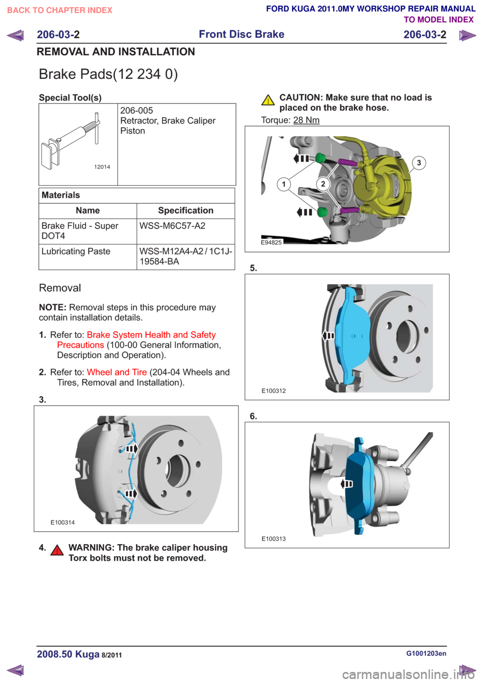
Brake Pads(12 234 0)
Special Tool(s)206-005
Retractor, Brake Caliper
Piston
12014
Materials
Specification
Name
WSS-M6C57-A2
Brake Fluid - Super
DOT4
WSS-M12A4-A2 / 1C1J-
19584-BA
Lubricating Paste
Removal
NOTE:
Removal steps in this procedure may
contain installation details.
1. Refer to: Brake System Health and Safety
Precautions (100-00 General Information,
Description and Operation).
2. Refer to: Wheel and Tire (204-04 Wheels and
Tires, Removal and Installation).
3.
E100314
4. WARNING: The brake caliper housing Torx bolts must not be removed.
CAUTION: Make sure that no load is
placed on the brake hose.
Torque: 28
Nm
E94825
12
3
5.
E100312
6.
E100313
G1001203en2008.50 Kuga8/2011
206-03- 2
Front Disc Brake
206-03- 2
REMOVAL AND INSTALLATION
TO MODEL INDEX
BACK TO CHAPTER INDEX
FORD KUGA 2011.0MY WORKSHOP REPAIR MANUAL