Page 1234 of 2057

Engine Speed Sensitive
This means that the vibration occurs at varying
vehicle speeds when a different transmission gear
is selected. It can sometimes be isolated by
increasing or decreasing engine speed with the
transmission in NEUTRAL or by stall testing with
the transmission in gear. If the condition is engine
speed sensitive, the cause is probably not related
to the tires.
If the road test indicates that there is tire whine,
but no shake or vibration, the noise originates with
the contact between the tire and the road surface.A thumping noise usually means that the tire is flat
or has soft spots making a noise as they slap the
roadway. Tire whine can be distinguished from axle
noise. Tire whine remains the same over a range
of speeds.
A complete road test procedure is described in
Section 100-04.
REFER to:
Noise, Vibration and Harshness (NVH)
(100-04 Noise, Vibration and Harshness,
Diagnosis and Testing).
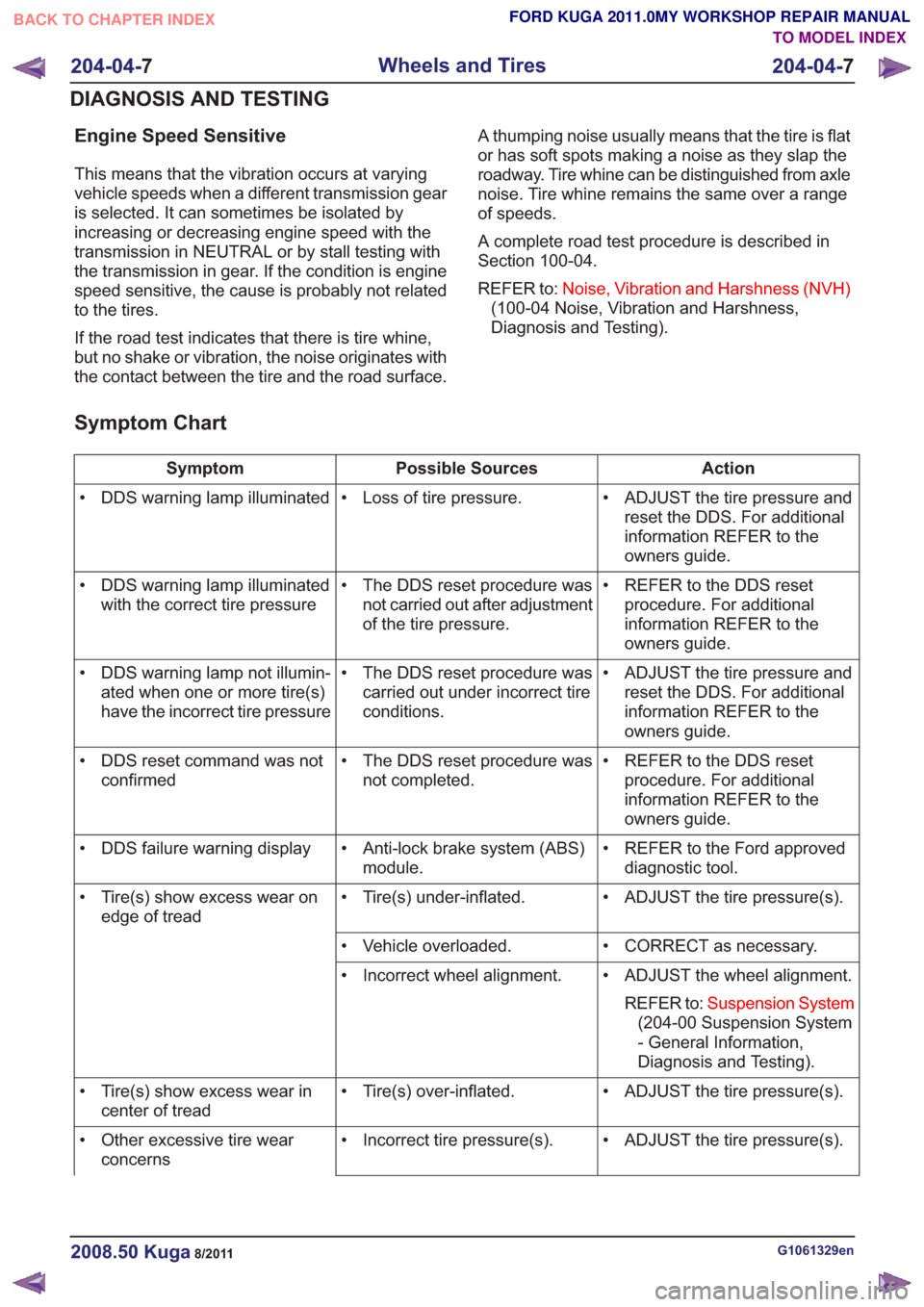
Symptom Chart
Action
Possible Sources
Symptom
• ADJUST the tire pressure andreset the DDS. For additional
information REFER to the
owners guide.
• Loss of tire pressure.
• DDS warning lamp illuminated
• REFER to the DDS resetprocedure. For additional
information REFER to the
owners guide.
• The DDS reset procedure was
not carried out after adjustment
of the tire pressure.
• DDS warning lamp illuminated
with the correct tire pressure
• ADJUST the tire pressure andreset the DDS. For additional
information REFER to the
owners guide.
• The DDS reset procedure was
carried out under incorrect tire
conditions.
• DDS warning lamp not illumin-
ated when one or more tire(s)
have the incorrect tire pressure
• REFER to the DDS resetprocedure. For additional
information REFER to the
owners guide.
• The DDS reset procedure was
not completed.
• DDS reset command was not
confirmed
• REFER to the Ford approveddiagnostic tool.
• Anti-lock brake system (ABS)
module.
• DDS failure warning display
• ADJUST the tire pressure(s).
• Tire(s) under-inflated.
• Tire(s) show excess wear on
edge of tread
• CORRECT as necessary.
• Vehicle overloaded.
• ADJUST the wheel alignment.REFER to: Suspension System
(204-00 Suspension System
- General Information,
Diagnosis and Testing).
• Incorrect wheel alignment.
• ADJUST the tire pressure(s).
• Tire(s) over-inflated.
• Tire(s) show excess wear in
center of tread
• ADJUST the tire pressure(s).
• Incorrect tire pressure(s).
• Other excessive tire wear
concerns
G1061329en2008.50 Kuga8/2011
204-04- 7
Wheels and Tires
204-04- 7
DIAGNOSIS AND TESTING
TO MODEL INDEX
BACK TO CHAPTER INDEX
FORD KUGA 2011.0MY WORKSHOP REPAIR MANUAL
Page 1238 of 2057
Wheel and Tire
Removal
CAUTION: Do not use heat to loosen a
seized wheel nut.
1. Loosen: 360°
E74933
x5
2.Refer to: Jacking(100-02 Jacking and Lifting,
Description and Operation).
Refer to: Lifting(100-02 Jacking and Lifting,
Description and Operation).
3.
E74934
x5
Installation
1. WARNING: Make sure that the mating faces are clean and free of corrosion
and foreign material
NOTE: Only tighten the nuts finger tight at this
stage.
E74934
x5
2. Lower the vehicle.
3. Tighten the wheel nuts in the sequence shown.
Torque: 130
Nm
E74931
1
43
25
G1000251en2008.50 Kuga8/2011
204-04- 11
Wheels and Tires
204-04- 11
REMOVAL AND INSTALLATION
TO MODEL INDEX
BACK TO CHAPTER INDEX
FORD KUGA 2011.0MY WORKSHOP REPAIR MANUAL
Page 1288 of 2057
1.Refer to: Health and Safety Precautions (100-00
General Information, Description and
Operation).
2. Refer to: Lifting(100-02 Jacking and Lifting,
Description and Operation).
3.
E114257
4. WARNING: Be prepared to collect escaping fluid.
E124748
5.
E124778
6. WARNING: Be prepared to collectescaping fluid.
x2x2
E124749
7.
E128365
G1268328en2008.50 Kuga8/2011
205-02- 43
Rear Drive Axle/Differential
205-02- 43
DISASSEMBLY AND ASSEMBLY
TO MODEL INDEX
BACK TO CHAPTER INDEX
FORD KUGA 2011.0MY WORKSHOP REPAIR MANUAL
Page 1291 of 2057
16.General Equipment: Puller
E114331
17. WARNING: Be prepared to collect
escaping fluid.
x2x2
E124753
Assembly
18.Material: Transmission Oil AWD
(8U7J-8708687-AA) transmission fluid
E124752
19. Torque: 6Nm
x2x2
E124753
G1268328en2008.50 Kuga8/2011
205-02- 46
Rear Drive Axle/Differential
205-02- 46
DISASSEMBLY AND ASSEMBLY
TO MODEL INDEX
BACK TO CHAPTER INDEX
FORD KUGA 2011.0MY WORKSHOP REPAIR MANUAL
Page 1301 of 2057
2.Refer to: Lifting(100-02 Jacking and Lifting,
Description and Operation).
Refer to: Wheel and Tire (204-04 Wheels and
Tires, Removal and Installation).
3. NOTE: This step is only necessary when
installing a new component.
E99269
4.
E101039
5. WARNING: Make sure that no load is placed on the brake hose.
E100801
G1076961en2008.50 Kuga8/2011
205-04- 6
Front Drive Halfshafts
205-04- 6
REMOVAL AND INSTALLATION
TO MODEL INDEX
BACK TO CHAPTER INDEX
FORD KUGA 2011.0MY WORKSHOP REPAIR MANUAL
Page 1304 of 2057
Vehicles with 6-speed manual transaxle
(MMT6)
17. WARNING: Be prepared to collectescaping fluid.
1. General Equipment: Tire Lever
2. Install the Special Tool(s): 205-775
1
205-7752
1
205-7752
E132274
Vehicles with 6-speed manual transmission
(M66)
18. WARNING: Be prepared to collectescaping fluid.
1. Install the Special Tool(s): 308-782
2. General Equipment: Tire Lever
3. Remove the Special Tool(s): 308-782
4. Install the Special Tool(s): 205-775
2
205-7754
308-7823
308-782
1
2
205-7754
308-7823
308-782
1
E132306
G1076961en2008.50 Kuga8/2011
205-04- 9
Front Drive Halfshafts
205-04- 9
REMOVAL AND INSTALLATION
TO MODEL INDEX
BACK TO CHAPTER INDEX
FORD KUGA 2011.0MY WORKSHOP REPAIR MANUAL
Page 1309 of 2057
7.
E132381
8.Torque: 83Nm
E97635
9. WARNING: Make sure that a new nut is
installed.
CAUTION: Make sure that the ball joint
ball does not rotate.
Torque: 80
Nm
E99197
10. N O T E : This step is only necessary when
installing a new component. NOTE:
Only tighten the nut finger tight at this
stage.
E132273
11 . If equipped.
Torque: 8
Nm
E125279
12.Torque: 5Nm
E132305
G1076961en2008.50 Kuga8/2011
205-04- 14
Front Drive Halfshafts
205-04- 14
REMOVAL AND INSTALLATION
TO MODEL INDEX
BACK TO CHAPTER INDEX
FORD KUGA 2011.0MY WORKSHOP REPAIR MANUAL
Page 1312 of 2057
4.
E102106
5. WARNING: Make sure that no load isplaced on the brake hose.
E100801
G1076962en2008.50 Kuga8/2011
205-04- 17
Front Drive Halfshafts
205-04- 17
REMOVAL AND INSTALLATION
TO MODEL INDEX
BACK TO CHAPTER INDEX
FORD KUGA 2011.0MY WORKSHOP REPAIR MANUAL