2011 FORD KUGA warning
[x] Cancel search: warningPage 1376 of 2057
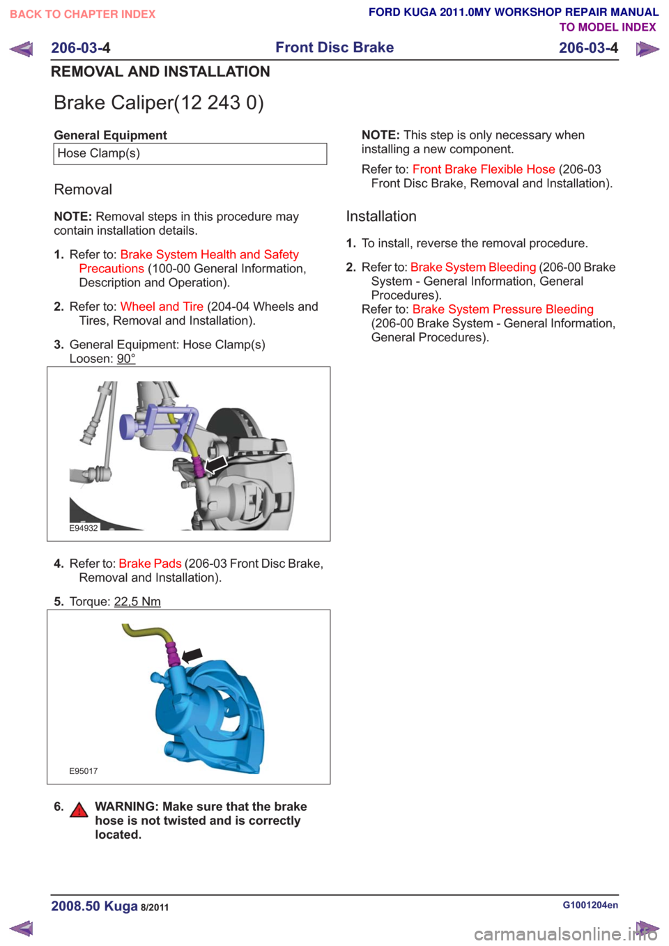
Brake Caliper(12 243 0)
General EquipmentHose Clamp(s)
Removal
NOTE: Removal steps in this procedure may
contain installation details.
1. Refer to: Brake System Health and Safety
Precautions (100-00 General Information,
Description and Operation).
2. Refer to: Wheel and Tire (204-04 Wheels and
Tires, Removal and Installation).
3. General Equipment: Hose Clamp(s)
Loosen: 90°
E94932
4.Refer to: Brake Pads (206-03 Front Disc Brake,
Removal and Installation).
5. Torque: 22,5
Nm
E95017
6. WARNING: Make sure that the brake
hose is not twisted and is correctly
located.
NOTE: This step is only necessary when
installing a new component.
Refer to: Front Brake Flexible Hose (206-03
Front Disc Brake, Removal and Installation).
Installation
1. To install, reverse the removal procedure.
2. Refer to: Brake System Bleeding (206-00 Brake
System - General Information, General
Procedures).
Refer to: Brake System Pressure Bleeding
(206-00 Brake System - General Information,
General Procedures).
G1001204en2008.50 Kuga8/2011
206-03- 4
Front Disc Brake
206-03- 4
REMOVAL AND INSTALLATION
TO MODEL INDEX
BACK TO CHAPTER INDEX
FORD KUGA 2011.0MY WORKSHOP REPAIR MANUAL
Page 1377 of 2057
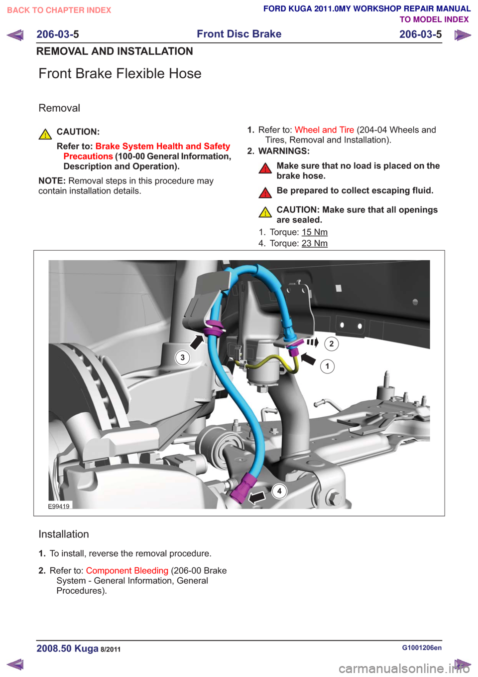
Front Brake Flexible Hose
Removal
CAUTION:
Refer to:Brake System Health and Safety
Precautions (100-00 General Information,
Description and Operation).
NOTE: Removal steps in this procedure may
contain installation details. 1.
Refer to: Wheel and Tire (204-04 Wheels and
Tires, Removal and Installation).
2. WARNINGS:
Make sure that no load is placed on the
brake hose.
Be prepared to collect escaping fluid.
CAUTION: Make sure that all openings
are sealed.
1. Torque: 15
Nm
4. Torque: 23Nm
E99419
1
2
3
4
Installation
1. To install, reverse the removal procedure.
2. Refer to: Component Bleeding (206-00 Brake
System - General Information, General
Procedures).
G1001206en2008.50 Kuga8/2011
206-03- 5
Front Disc Brake
206-03- 5
REMOVAL AND INSTALLATION
TO MODEL INDEX
BACK TO CHAPTER INDEX
FORD KUGA 2011.0MY WORKSHOP REPAIR MANUAL
Page 1379 of 2057
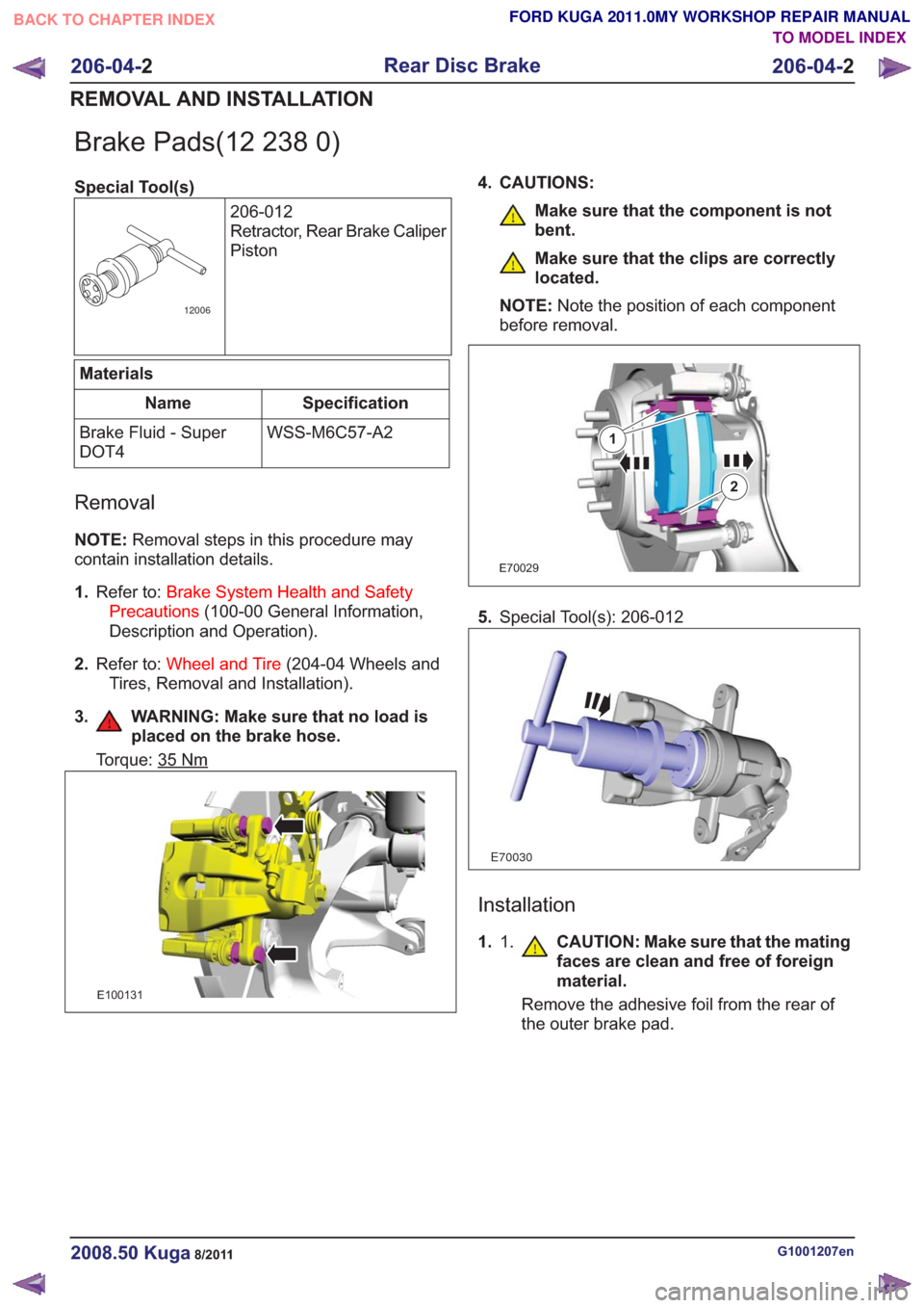
Brake Pads(12 238 0)
Special Tool(s)206-012
Retractor, Rear Brake Caliper
Piston
12006
Materials
Specification
Name
WSS-M6C57-A2
Brake Fluid - Super
DOT4
Removal
NOTE: Removal steps in this procedure may
contain installation details.
1. Refer to: Brake System Health and Safety
Precautions (100-00 General Information,
Description and Operation).
2. Refer to: Wheel and Tire (204-04 Wheels and
Tires, Removal and Installation).
3. WARNING: Make sure that no load is placed on the brake hose.
Torque: 35Nm
E100131
4. CAUTIONS:
Make sure that the component is not
bent.
Make sure that the clips are correctly
located.
NOTE: Note the position of each component
before removal.
E70029
1
2
5. Special Tool(s): 206-012
E70030
Installation
1. 1. CAUTION: Make sure that the mating
faces are clean and free of foreign
material.
Remove the adhesive foil from the rear of
the outer brake pad.
G1001207en2008.50 Kuga8/2011
206-04- 2
Rear Disc Brake
206-04- 2
REMOVAL AND INSTALLATION
TO MODEL INDEX
BACK TO CHAPTER INDEX
FORD KUGA 2011.0MY WORKSHOP REPAIR MANUAL
Page 1382 of 2057
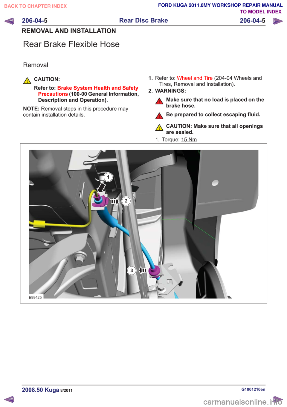
Rear Brake Flexible Hose
Removal
CAUTION:
Refer to:Brake System Health and Safety
Precautions (100-00 General Information,
Description and Operation).
NOTE: Removal steps in this procedure may
contain installation details. 1.
Refer to: Wheel and Tire (204-04 Wheels and
Tires, Removal and Installation).
2. WARNINGS:
Make sure that no load is placed on the
brake hose.
Be prepared to collect escaping fluid.
CAUTION: Make sure that all openings
are sealed.
1. Torque: 15
Nm
E99425
1
2
3
G1001210en2008.50 Kuga8/2011
206-04- 5
Rear Disc Brake
206-04- 5
REMOVAL AND INSTALLATION
TO MODEL INDEX
BACK TO CHAPTER INDEX
FORD KUGA 2011.0MY WORKSHOP REPAIR MANUAL
Page 1387 of 2057
Parking Brake
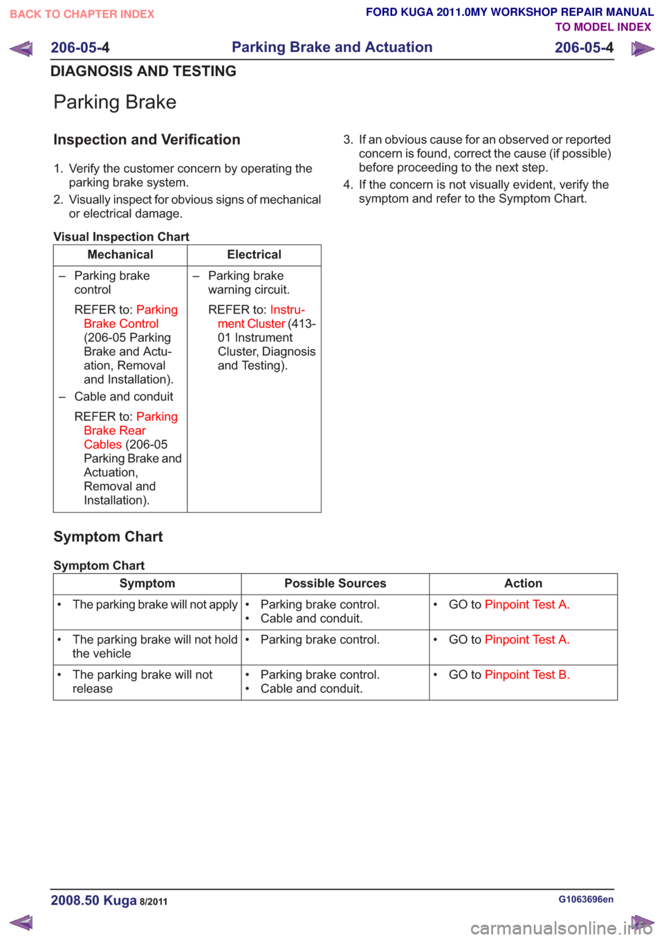
Inspection and Verification
1. Verify the customer concern by operating theparking brake system.
2. Visually inspect for obvious signs of mechanical or electrical damage.
Visual Inspection Chart
Electrical
Mechanical
– Parking brakewarning circuit.
REFER to: Instru-
ment Cluster (413-
01 Instrument
Cluster, Diagnosis
and Testing).
– Parking brake
control
REFER to: Parking
Brake Control
(206-05 Parking
Brake and Actu-
ation, Removal
and Installation).
– Cable and conduit
REFER to: Parking
Brake Rear
Cables (206-05
Parking Brake and
Actuation,
Removal and
Installation). 3. If an obvious cause for an observed or reported
concern is found, correct the cause (if possible)
before proceeding to the next step.
4. If the concern is not visually evident, verify the symptom and refer to the Symptom Chart.
Symptom Chart
Symptom Chart
Action
Possible Sources
Symptom
• GO toPinpoint Test A.
• Parking brake control.
• Cable and conduit.
• The parking brake will not apply
• GO toPinpoint Test A.
• Parking brake control.
• The parking brake will not hold
the vehicle
• GO toPinpoint Test B.
• Parking brake control.
• Cable and conduit.
• The parking brake will not
release
G1063696en2008.50 Kuga8/2011
206-05- 4
Parking Brake and Actuation
206-05- 4
DIAGNOSIS AND TESTING
TO MODEL INDEX
BACK TO CHAPTER INDEX
FORD KUGA 2011.0MY WORKSHOP REPAIR MANUAL
Page 1429 of 2057
HCU to check for sudden actuation of the brakes.
With the brake pedal pressed, the ABS module
triggers emergency braking if the rate of increase
of hydraulic pressure exceeds the predetermined
limit.
If the brake pedal is pressed so hard that the ABS
becomes active on the front wheels then the ABS
control unit increases the pressure to the rear
wheel brakes up to the ABS intervention threshold.
EBA operation continues until the driver releases
the brake pedal sufficiently for the hydraulic
pressure in the HCU to drop below a threshold
value stored in the ABS module.
Trailer stability control:If the vehicle is ordered
with a trailer coupling then the Trailer Stability
Control function is integrated in the ESP. The ESP
detects snaking when driving with a trailer and
reduces the speed of the vehicle and trailer through
adapted braking and, if necessary, by also reducing
the engine output until the snaking movement of
the trailer is corrected.
Roll-over protection: The ESP dynamically
determines the tipping tendency of the vehicle and
works in conjunction with the EBA system to
prevent the vehicle from tipping over during
dynamic maneuvers like lane changing or while
negotiating bends.
Emergency brake light: The emergency brake
light automatically switches on the hazard flasher
system to warn drivers of other vehicles that
emergency braking is being initiated. Based on a
defined delay value, the ABS/ESP module sends
a signal to the generic electronic module (GEM)
via the CAN data bus. The GEM activates the
hazard flasher system, that then flashes 7 times.
Prerequisites for activation of the emergency brake
light are:
• The speed is higher than 50 km/h.
• The brake pedal is being actuated.
• The deceleration is greater than 9 m/s².
To prevent activation on snow or ice, for example,
the following prerequisites must be met:
• The speed is higher than 50 km/h.
• The brake pedal is being actuated.
• ABS regulation takes place.
• The deceleration is greater than 6 m/s².
Tire pressure monitoring system: The tire
pressure monitoring system used in the Kuga is
able to detect loss of air in a tire at an early stage
and warn the driver. Because it can only compare
the behaviour of the tyres with each other, it is not possible to draw conclusions about the absolute
tyre pressure. It is also not possible to monitor the
spare tyre pressure. In order for the system to
operate correctly, the tyre pressures must be
regularly checked and corrected and the system
subsequently initialised (see below).
The tire pressure monitoring system used here,
depending on the equipment level, is built into the
anti-lock braking system (ABS) as an extra function
and therefore does not have its own sensors.
The ABS module measures the loss of pressure
in the tyres by calculation using the wheel speed
sensors of the ABS system. If a tyre loses
pressure, its diameter decreases and the speed of
the wheel therefore increases. If the ABS module
detects such a loss in pressure, it sends a signal
to the instrument cluster via the CAN bus and a
warning message is displayed in the message
centre. The warning threshold depends among
other things on the dimension of the tyres being
used, the vehicle operating conditions and the
status at the last initialisation. Since neither the
absolute tyre pressure nor the position of the tyre
is known, the pressure of all the tyres must be
checked and the system re-initialised after a tyre
pressure warning. If necessary, the cause of the
loss of pressure must be investigated.
Regular tyre pressure checks are still necessary.
The system must be initialised after a tyre is
changed, winter or summer tyres fitted, the
pressures corrected or adjusted to suit the vehicle
load. This can be done by the driver using the
driver information system. For further information,
see: Owner’s Manual.
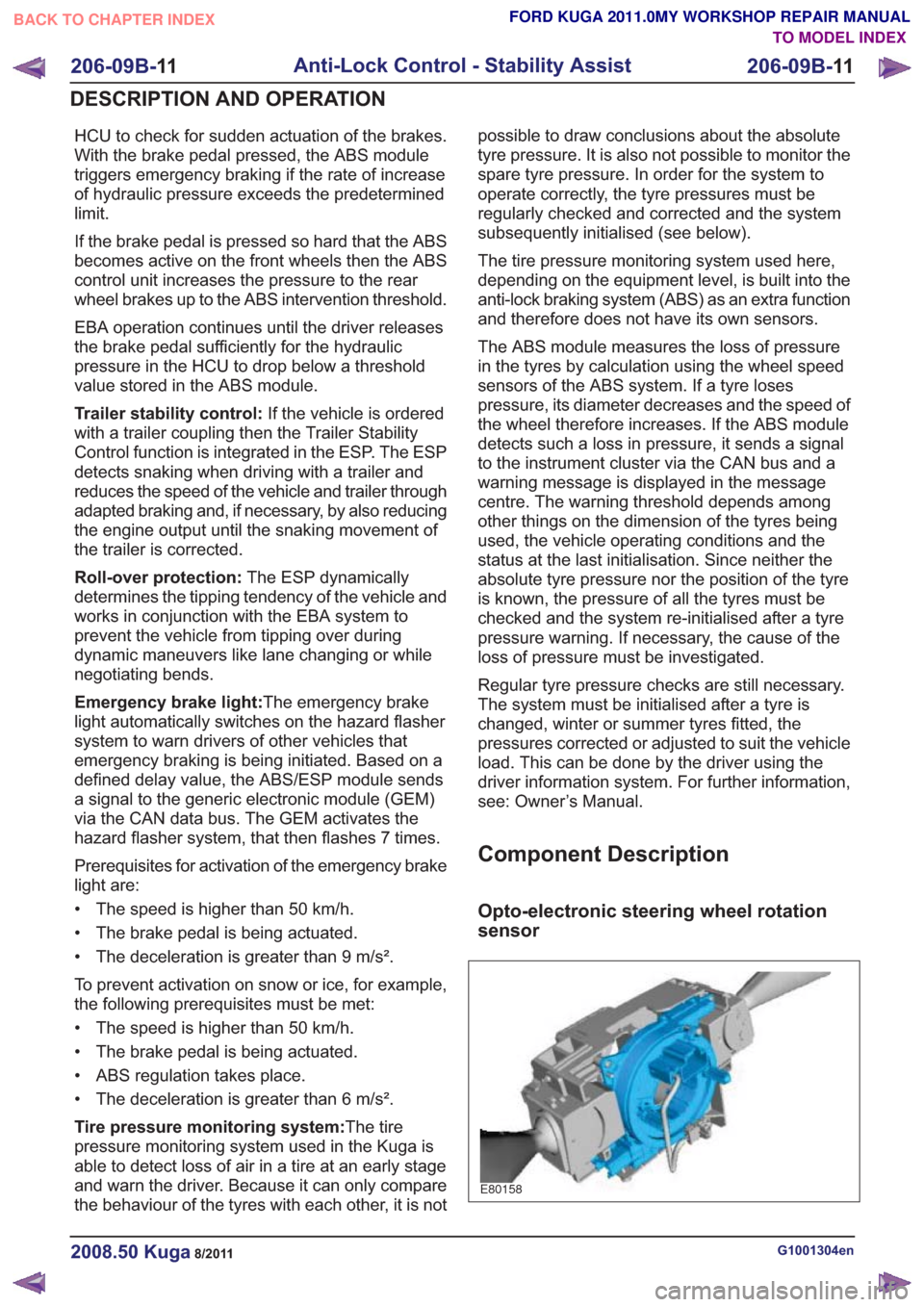
Component Description
Opto-electronic steering wheel rotation
sensor
E80158
G1001304en2008.50 Kuga8/2011
206-09B-
11
Anti-Lock Control - Stability Assist
206-09B- 11
DESCRIPTION AND OPERATION
TO MODEL INDEX
BACK TO CHAPTER INDEX
FORD KUGA 2011.0MY WORKSHOP REPAIR MANUAL
Page 1437 of 2057
Stability Assist Module
General EquipmentFord approved diagnostic tool
Pneumatic Vacuum GunMaterials
Specification
Name
WSK-M2G342-A /
2U7J-M2G400-AA
Metal Adhesive Kit - 2
Component
Removal
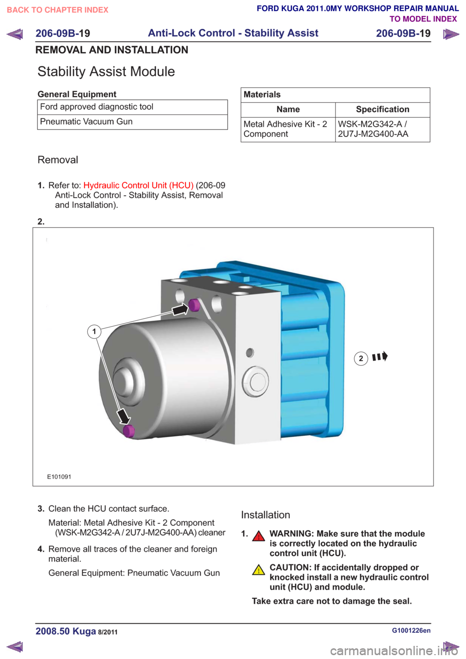
1.
Refer to: Hydraulic Control Unit (HCU) (206-09
Anti-Lock Control - Stability Assist, Removal
and Installation).
2.
E101091
1
2
3. Clean the HCU contact surface.
Material: Metal Adhesive Kit - 2 Component
(WSK-M2G342-A / 2U7J-M2G400-AA) cleaner
4. Remove all traces of the cleaner and foreign
material.
General Equipment: Pneumatic Vacuum GunInstallation
1. WARNING: Make sure that the module
is correctly located on the hydraulic
control unit (HCU).
CAUTION: If accidentally dropped or
knocked install a new hydraulic control
unit (HCU) and module.
Take extra care not to damage the seal.
G1001226en2008.50 Kuga8/2011
206-09B- 19
Anti-Lock Control - Stability Assist
206-09B- 19
REMOVAL AND INSTALLATION
TO MODEL INDEX
BACK TO CHAPTER INDEX
FORD KUGA 2011.0MY WORKSHOP REPAIR MANUAL
Page 1443 of 2057
Steering System
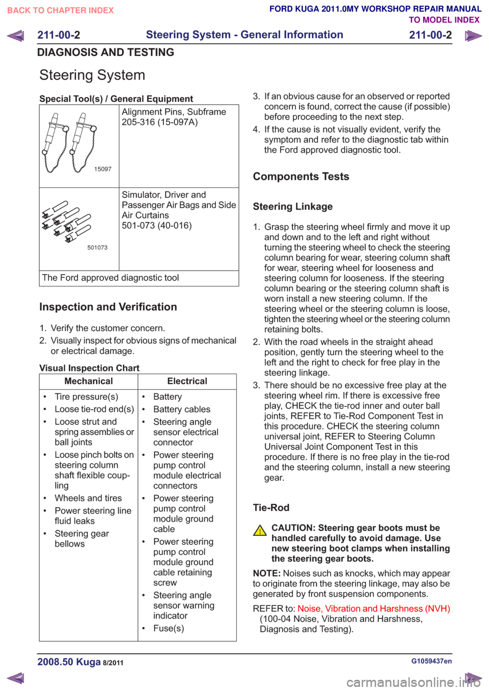
Special Tool(s) / General EquipmentAlignment Pins, Subframe
205-316 (15-097A)
15097
Simulator, Driver and
Passenger Air Bags and Side
Air Curtains
501-073 (40-016)
501073
The Ford approved diagnostic tool
Inspection and Verification
1. Verify the customer concern.
2. Visually inspect for obvious signs of mechanicalor electrical damage.
Visual Inspection Chart
Electrical
Mechanical
• Battery
• Battery cables
• Steering anglesensor electrical
connector
• Power steering pump control
module electrical
connectors
• Power steering pump control
module ground
cable
• Power steering pump control
module ground
cable retaining
screw
• Steering angle sensor warning
indicator
• Fuse(s)
• Tire pressure(s)
• Loose tie-rod end(s)
• Loose strut and
spring assemblies or
ball joints
• Loose pinch bolts on steering column
shaft flexible coup-
ling
• Wheels and tires
• Power steering line fluid leaks
• Steering gear bellows 3. If an obvious cause for an observed or reported
concern is found, correct the cause (if possible)
before proceeding to the next step.
4. If the cause is not visually evident, verify the symptom and refer to the diagnostic tab within
the Ford approved diagnostic tool.
Components Tests
Steering Linkage
1. Grasp the steering wheel firmly and move it upand down and to the left and right without
turning the steering wheel to check the steering
column bearing for wear, steering column shaft
for wear, steering wheel for looseness and
steering column for looseness. If the steering
column bearing or the steering column shaft is
worn install a new steering column. If the
steering wheel or the steering column is loose,
tighten the steering wheel or the steering column
retaining bolts.
2. With the road wheels in the straight ahead position, gently turn the steering wheel to the
left and the right to check for free play in the
steering linkage.
3. There should be no excessive free play at the steering wheel rim. If there is excessive free
play, CHECK the tie-rod inner and outer ball
joints, REFER to Tie-Rod Component Test in
this procedure. CHECK the steering column
universal joint, REFER to Steering Column
Universal Joint Component Test in this
procedure. If there is no free play in the tie-rod
and the steering column, install a new steering
gear.
Tie-Rod
CAUTION: Steering gear boots must be
handled carefully to avoid damage. Use
new steering boot clamps when installing
the steering gear boots.
NOTE: Noises such as knocks, which may appear
to originate from the steering linkage, may also be
generated by front suspension components.
REFER to: Noise, Vibration and Harshness (NVH)
(100-04 Noise, Vibration and Harshness,
Diagnosis and Testing).
G1059437en2008.50 Kuga8/2011
211-00- 2
Steering System - General Information
211-00- 2
DIAGNOSIS AND TESTING
TO MODEL INDEX
BACK TO CHAPTER INDEX
FORD KUGA 2011.0MY WORKSHOP REPAIR MANUAL