Page 1493 of 2057
Steering Gear to Power Steering Fluid Reservoir Return Line —2.5L Duratec (147kW/200PS) - VI5(13 439 0)
General Equipment
Hose Clamp Remover/Installer
Removal
NOTE: Removal steps in this procedure may
contain installation details.
1. Refer to: Steering System Health and Safety
Precautions (100-00 General Information,
Description and Operation).
2. Refer to: Wheel and Tire (204-04 Wheels and
Tires, Removal and Installation).
3.
E98543
x7
4.
E99630
5.
E99631
6. WARNING: Be prepared to collect escaping fluid.
1. General Equipment: Hose ClampRemover/Installer
2. Torque: 30
Nm
E114706
1
2
7. Torque: 23Nm1.
2. Torque: 7
Nm
G1185536en2008.50 Kuga8/2011
211-02- 36
Power Steering
211-02- 36
REMOVAL AND INSTALLATION
TO MODEL INDEX
BACK TO CHAPTER INDEX
FORD KUGA 2011.0MY WORKSHOP REPAIR MANUAL
Page 1494 of 2057
E112634
2
1
8.Torque: 4Nm
E99258
9. WARNING: Be prepared to collect
escaping fluid.
CAUTION: Make sure that all openings
are sealed.
Torque: 18
Nm
E114705
10.
G1185536en2008.50 Kuga8/2011
211-02- 37
Power Steering
211-02- 37
REMOVAL AND INSTALLATION
TO MODEL INDEX
BACK TO CHAPTER INDEX
FORD KUGA 2011.0MY WORKSHOP REPAIR MANUAL
Page 1506 of 2057
Steering Column(13 542 0)
Removal
WARNINGS:
The supplemental restraint system (SRS)
is active for a certain length of time after
the power supply has been disconnected.
Wait for a minimum of 3 minutes before
disconnecting or removing any SRS
components.
Make sure that the vehicle electrical
system is fully depowered and no other
power source is connected.
NOTE: Removal steps in this procedure may
contain installation details.
1. NOTE: Make sure that the road wheels are in
the straight ahead position.
E99259
2. CAUTION: Make sure that the steering wheel lock is engaged.
Refer to: Battery Disconnect and Connect
(414-01 Battery, Mounting and Cables,
General Procedures).
3. If equipped.
E100834
4.
E95563
5.
E99639
1
2
6.
E99720
G1058718en2008.50 Kuga8/2011
211-04- 5
Steering Column
211-04- 5
REMOVAL AND INSTALLATION
TO MODEL INDEX
BACK TO CHAPTER INDEX
FORD KUGA 2011.0MY WORKSHOP REPAIR MANUAL
Page 1508 of 2057

Steering Column Shaft
Removal
WARNINGS:
The supplemental restraint system (SRS)
is active for a certain length of time after
the power supply has been disconnected.
Wait for a minimum of 3 minutes before
disconnecting or removing any SRS
components.
Make sure that the vehicle electrical
system is fully depowered and no other
power source is connected.
NOTE: Removal steps in this procedure may
contain installation details.
1. Refer to: Clockspring (501-20 Supplemental
Restraint System, Removal and Installation).
Refer to: Steering Column Multifunction Switch
LH (211-05 Steering Column Switches,
Removal and Installation).
Refer to: Steering Column Multifunction Switch
RH (211-05 Steering Column Switches,
Removal and Installation).
Refer to: Steering Column Lock Module (211-05
Steering Column Switches, Removal and
Installation).
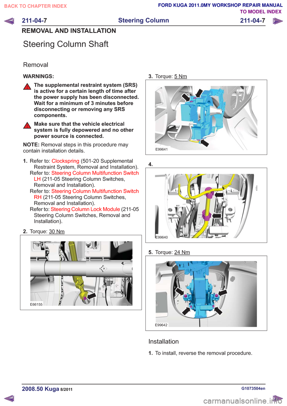
2. Torque: 30
Nm
E66155
3.Torque: 5Nm
E99641
4.
E99640
5.Torque: 24Nm
E99642
Installation
1.To install, reverse the removal procedure.
G1073504en2008.50 Kuga8/2011
211-04- 7
Steering Column
211-04- 7
REMOVAL AND INSTALLATION
TO MODEL INDEX
BACK TO CHAPTER INDEX
FORD KUGA 2011.0MY WORKSHOP REPAIR MANUAL
Page 1525 of 2057

Action
Possible Sources
Symptom
• CHECK the engine compon-ents for wear or damage. Make
sure that all components are
within specification. INSTALL
new components as necessary.
Engine - 2.5L Duratec-ST (VI5)
-
REFER to: Specifications (303-
01 Engine - 2.5L Duratec
(147kW/200PS) - VI5,
Specifications).
Engine - 2.0L Duratorq-TDCi
(DW) Diesel -
• Engine components
- Pistons.
- Piston rings.
- Connecting rod big end,main bearing or thrust
bearing journals.
- Connecting rods bent or damaged.
• Noisy running or engine noise
Engine - Oil Leaks
NOTE:
Before installing new gaskets or oil seals,
make sure that the fault is clearly established.
If the oil leak cannot be identified clearly by a visual
inspection, carry out an ultraviolet (UV) test:
Ultraviolet (UV) Testing
1. Clean the engine and transmission with a suitable cleaning fluid.
2. Pour the UV-test fluid in accordance with the quantity specified by the manufacturer through
the oil filler neck into the engine and install the
oil filler cap.
WARNING: Vehicles with manual transaxle,
shift the transaxle into Neutral. Failure to
follow this instruction may result in
personal injury.
3. Start the engine and let it run for about five minutes.
4. Switch off the engine.
NOTE: If no leak can be found, road test the
vehicle under various loads and check the engine
for leaks again.
5. Check the engine for oil leaks using a suitable UV lamp.
6. Rectify any leaks found and check the engine for oil leaks.
Measure the compression pressure
NOTE: The powertrain control module (PCM)
receives an error message when the fuel pump
relay is removed or electrical components are disconnected. This error message must be deleted
from the fault memory using the Ford diagnostic
equipment after completing the compression test.
NOTE:
Valve clearance must be set correctly
before performing a compression test. Make sure
the engine is at the normal operating temperature.
NOTE: The varying design of compression
checking devices and fluctuating starter motor
speeds normally only allows for a comparison to
be made of the compression pressures in all
cylinders.
G1055128en2008.50 Kuga8/2011
303-00- 9
Engine System - General Information
303-00- 9
DIAGNOSIS AND TESTING
TO MODEL INDEX
BACK TO CHAPTER INDEX
FORD KUGA 2011.0MY WORKSHOP REPAIR MANUAL
Page 1527 of 2057

9. Install the ignition coil-on-plug.REFER to: Ignition Coil-On-Plug (303-07 Engine
Ignition - 2.5L Duratec (147kW/200PS) - VI5,
Removal and Installation).
TIE44609
10. Install the fuel pump relay and close the CJB.
TIE44608
11. Install the CJB cover.
Measure the compression pressure
(Engine - 2.0L Duratorq-TDCi (DW)
Diesel)
WARNINGS:
Do not smoke or carry lighted tobacco or
open flame of any type when working on or near any fuel related components.
Highly flammable vapors are always
present and can ignite. Failure to follow
these instructions may result in personal
injury.
Do not carry out any repairs to the fuel
injection system without checking that the
fuel pressure has dropped to zero and that
the fuel temperature has either reached
ambient temperature or is below 30°C,
whichever is the greater. Failure to follow
these instructions may result in personal
injury.
1. Using datalogger in the Ford diagnostic
equipment , check that the fuel pressure has
dropped to zero and that the fuel temperature
has either reached ambient temperature or is
below 30°C, whichever is the greater.
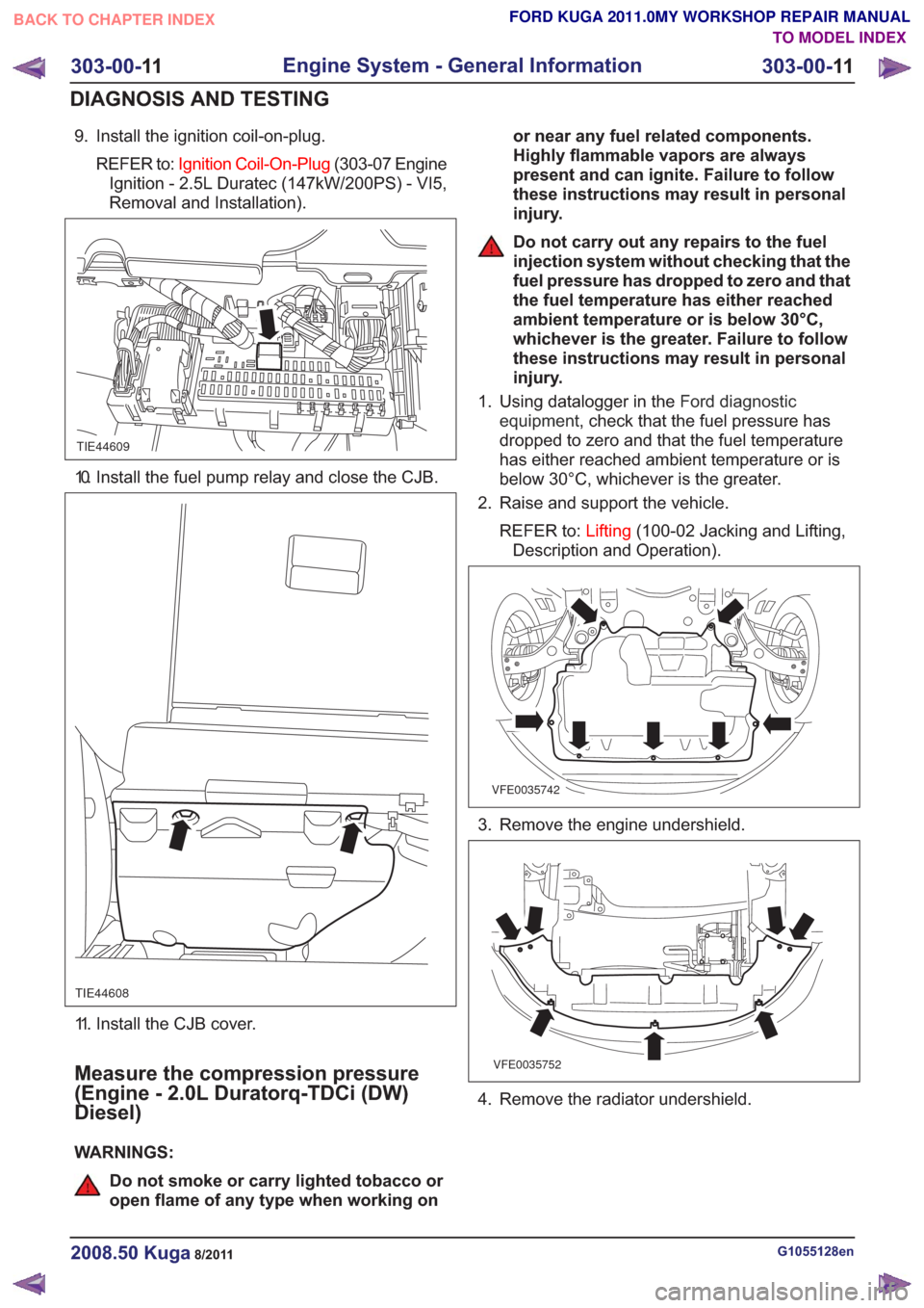
2. Raise and support the vehicle.
REFER to: Lifting(100-02 Jacking and Lifting,
Description and Operation).
VFE0035742
3. Remove the engine undershield.
VFE0035752
4. Remove the radiator undershield.
G1055128en2008.50 Kuga8/2011
303-00- 11
Engine System - General Information
303-00- 11
DIAGNOSIS AND TESTING
TO MODEL INDEX
BACK TO CHAPTER INDEX
FORD KUGA 2011.0MY WORKSHOP REPAIR MANUAL
Page 1560 of 2057
Vehicles with mechanical timing belt tensioner
9.
E68488
1
3
2
Vehicles with automatic timing belt tensioner
10. WARNING: Take extra care whenhandling the compressed spring.
Install the Special Tool(s): 303-1054
1
2
E113799
303-1054
11. WARNING: Take extra care whenhandling the compressed spring.
Special Tool(s): 303-1054
E113800
1
2
3
303-1054
G543492en2008.50 Kuga8/2011
303-01- 27
Engine— 2.5L Duratec (147kW/200PS) - VI5303-01-
27
REMOVAL AND INSTALLATION
TO MODEL INDEX
BACK TO CHAPTER INDEX
FORD KUGA 2011.0MY WORKSHOP REPAIR MANUAL
Page 1561 of 2057
Installation
Vehicles with mechanical timing belt tensioner
1. NOTE:Make sure that new components are
installed.
1. Torque: 25
Nm
3. Torque: 25Nm
E68489
3
1
2
-20 C 20 C 50 C
Vehicles with automatic timing belt tensioner
2. NOTE: Make sure that new components are
installed.
1. Torque: 25
Nm
3. Special Tool(s): 303-1054 Torque: 25
Nm
E113801
12
3
303-1054
3. WARNING: Take extra care when handling the compressed spring.
Remove the Special Tool(s): 303-1054
E113802
303-1054
G543492en2008.50 Kuga8/2011
303-01- 28
Engine— 2.5L Duratec (147kW/200PS) - VI5303-01-
28
REMOVAL AND INSTALLATION
TO MODEL INDEX
BACK TO CHAPTER INDEX
FORD KUGA 2011.0MY WORKSHOP REPAIR MANUAL