Page 1874 of 2057

well as vehicle speed, driving comfort is improved
by linear actuation of the TCC.
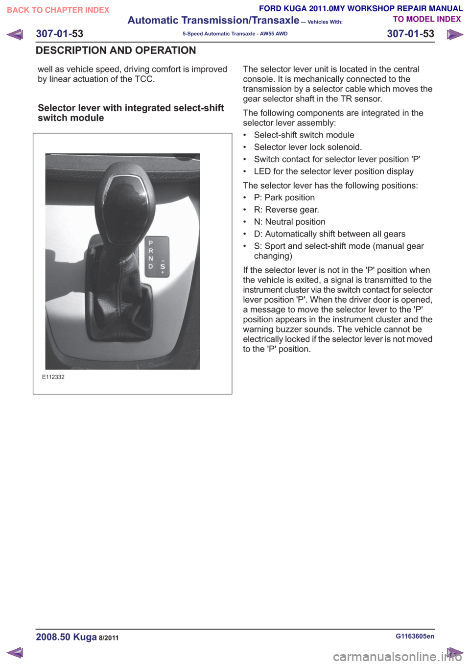
Selector lever with integrated select-shift
switch module
E112332
The selector lever unit is located in the central
console. It is mechanically connected to the
transmission by a selector cable which moves the
gear selector shaft in the TR sensor.
The following components are integrated in the
selector lever assembly:
• Select-shift switch module
• Selector lever lock solenoid.
• Switch contact for selector lever position 'P'
• LED for the selector lever position display
The selector lever has the following positions:
• P: Park position
• R: Reverse gear.
• N: Neutral position
• D: Automatically shift between all gears
• S: Sport and select-shift mode (manual gearchanging)
If the selector lever is not in the 'P' position when
the vehicle is exited, a signal is transmitted to the
instrument cluster via the switch contact for selector
lever position 'P'. When the driver door is opened,
a message to move the selector lever to the 'P'
position appears in the instrument cluster and the
warning buzzer sounds. The vehicle cannot be
electrically locked if the selector lever is not moved
to the 'P' position.
G1163605en2008.50 Kuga8/2011
307-01- 53
Automatic Transmission/Transaxle
— Vehicles With:
5-Speed Automatic Transaxle - AW55 AWD
307-01- 53
DESCRIPTION AND OPERATION
TO MODEL INDEX
BACK TO CHAPTER INDEX
FORD KUGA 2011.0MY WORKSHOP REPAIR MANUAL
Page 1882 of 2057

Transmission Fluid Level Check
General EquipmentFord Diagnostic Equipment
Materials
Specification
Name
WSS-M2C924-A / 4U7J-
M2C924-AA
Automatic Transmission
Oil E-AW
Inspection
1.
Refer to: Health and Safety Precautions (100-00
General Information, Description and
Operation).
2. Connect the Ford diagnostic equipment.
General Equipment: Ford Diagnostic Equipment
3. Make sure that the transmission is not in
emergency operation mode.
4. Make sure that the transmission fluid
temperature is between 70° and 80°C.
General Equipment: Ford Diagnostic Equipment
80
70
E114667
5. WARNING: Make sure that the brake pedal and parking brake are fully applied
during the test.
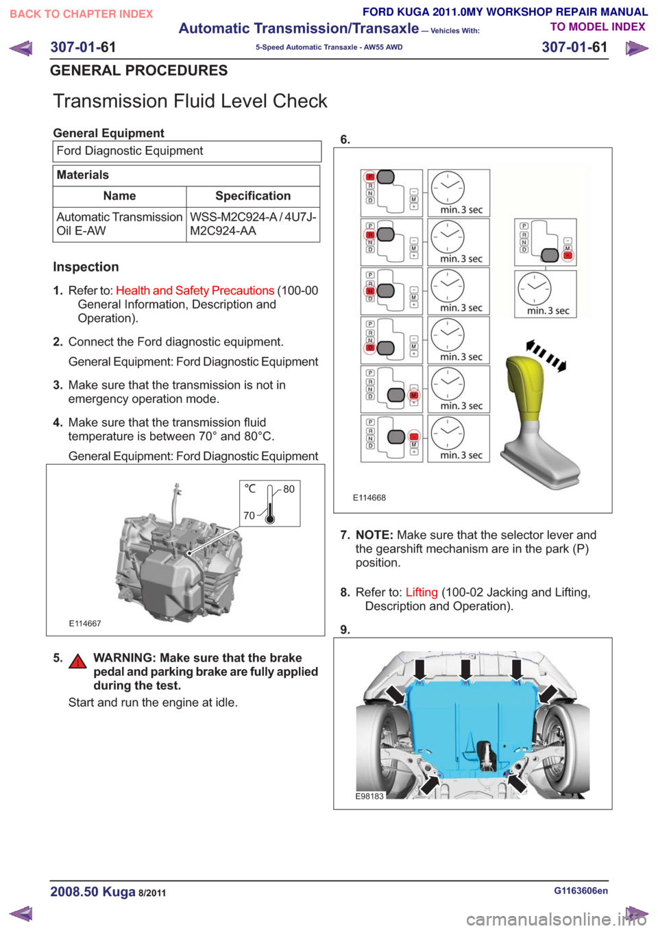
Start and run the engine at idle. 6.
E114668
7. NOTE:
Make sure that the selector lever and
the gearshift mechanism are in the park (P)
position.
8. Refer to: Lifting(100-02 Jacking and Lifting,
Description and Operation).
9.
E98183
G1163606en2008.50 Kuga8/2011
307-01- 61
Automatic Transmission/Transaxle
— Vehicles With:
5-Speed Automatic Transaxle - AW55 AWD
307-01- 61
GENERAL PROCEDURES
TO MODEL INDEX
BACK TO CHAPTER INDEX
FORD KUGA 2011.0MY WORKSHOP REPAIR MANUAL
Page 1884 of 2057
Transmission Fluid Drain and Refill
General EquipmentFluid Container
Materials
Specification
Name
WSS-M2C924-A / 4U7J-
M2C924-AA
Automatic Transmission
Oil E-AW
Draining
17.
Refer to: Health and Safety Precautions (100-00
General Information, Description and
Operation).
18. Refer to: Lifting(100-02 Jacking and Lifting,
Description and Operation).
19.
E98183
20. WARNING: Be prepared to collect escaping fluid.
General Equipment: Fluid Container
E114758
21.Torque: 40Nm
E114758
Filling
22.
E114670
23.Use a suitable plastic tube.
E114933
G1163607en2008.50 Kuga8/2011
307-01- 63
Automatic Transmission/Transaxle
— Vehicles With:
5-Speed Automatic Transaxle - AW55 AWD
307-01- 63
GENERAL PROCEDURES
TO MODEL INDEX
BACK TO CHAPTER INDEX
FORD KUGA 2011.0MY WORKSHOP REPAIR MANUAL
Page 1893 of 2057
Output Shaft Speed (OSS) Sensor
MaterialsSpecification
Name
WSS-M2C924-A / 4U7J-
M2C924-AA
Automatic Transmission
Oil E-AW
Removal
1.
Refer to: Health and Safety Precautions (100-00
General Information, Description and
Operation).
2. WARNING: Be prepared to collect escaping fluid.
E115345
3.
E115335
Installation
1. NOTE: Make sure that a new component is
installed.
Material: Automatic Transmission Oil E-AW (WSS-M2C924-A / 4U7J-M2C924-AA)
transmission fluid
E115336
2. WARNING: Make sure that a new bolt is installed.
Torque: 5Nm
E115253
G1163635en2008.50 Kuga8/2011
307-01- 72
Automatic Transmission/Transaxle
— Vehicles With:
5-Speed Automatic Transaxle - AW55 AWD
307-01- 72
REMOVAL AND INSTALLATION
TO MODEL INDEX
BACK TO CHAPTER INDEX
FORD KUGA 2011.0MY WORKSHOP REPAIR MANUAL
Page 1902 of 2057
Turbine Shaft Speed (TSS) Sensor
MaterialsSpecification
Name
WSS-M2C924-A / 4U7J-
M2C924-AA
Automatic Transmission
Oil E-AW
Removal
1.
Refer to: Health and Safety Precautions (100-00
General Information, Description and
Operation).
2.
E115344
3.
E115335
Installation
1. NOTE: Make sure that a new component is
installed.
Material: Automatic Transmission Oil E-AW (WSS-M2C924-A / 4U7J-M2C924-AA)
transmission fluid
E115336
2. WARNING: Make sure that a new bolt is installed.
Torque: 5Nm
E115252
G1163632en2008.50 Kuga8/2011
307-01- 81
Automatic Transmission/Transaxle
— Vehicles With:
5-Speed Automatic Transaxle - AW55 AWD
307-01- 81
REMOVAL AND INSTALLATION
TO MODEL INDEX
BACK TO CHAPTER INDEX
FORD KUGA 2011.0MY WORKSHOP REPAIR MANUAL
Page 1911 of 2057
38.
E114622
39.Install the following items:
1. General Equipment: Wooden Block General Equipment: Transmission Jack
E114733
40.
E114621
41.
x2x2
E114623
42. WARNING: This step requires the aid of another technician.
General Equipment: Transmission Jack
x2x2
E114734
G1163644en2008.50 Kuga8/2011
307-01- 90
Automatic Transmission/Transaxle
— Vehicles With:
5-Speed Automatic Transaxle - AW55 AWD
307-01- 90
REMOVAL
TO MODEL INDEX
BACK TO CHAPTER INDEX
FORD KUGA 2011.0MY WORKSHOP REPAIR MANUAL
Page 1912 of 2057

Transmission
Installation
Special Tool(s) / General Equipment303-290-01
Adapter for 303-290A
2114001
303-290-03A
Adapter for 303-290A
30329003A
303-290-05A
Adapter for 303-290A
30329005A
303-290A
Support Bar, Engine
303290A
303-290A-14
Adapter for 303-290A
303290A14
Cable Ties
Round-Ended Steel Rule
Transmission Jack
Wooden Block
Materials
Specification
Name
ESD-M1C220-A /
A88SX1C220AA
Grease K-HT
SA-M1C9107-A / YS5J-
M1C9107-AA
Grease KS-PS
1. Refer to: Health and Safety Precautions (100-00
General Information, Description and
Operation).
2. Refer to: Lifting(100-02 Jacking and Lifting,
Description and Operation).
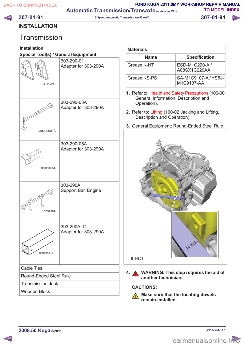
3. General Equipment: Round-Ended Steel Rule
14 mm14 mm
E114801
4. WARNING: This step requires the aid of
another technician.
CAUTIONS:
Make sure that the locating dowels
remain installed.
G1163646en2008.50 Kuga8/2011
307-01- 91
Automatic Transmission/Transaxle
— Vehicles With:
5-Speed Automatic Transaxle - AW55 AWD
307-01- 91
INSTALLATION
TO MODEL INDEX
BACK TO CHAPTER INDEX
FORD KUGA 2011.0MY WORKSHOP REPAIR MANUAL
Page 1970 of 2057

Fuel System — Vehicles With: Fuel Additive Tank
General EquipmentFord diagnostic equipment
Principles of Operation
WARNINGS:
This procedure involves fuel additive
handling. Be prepared for fuel additive
spillage at all times and always observe
fuel handling precautions. Failure to follow
these instructions may result in personal
injury.
Eye, hand, ear protection and protective
clothing are required to be worn during
any general service or removal and
installation service procedure of fuel
additive system components. Failure to
follow this instruction may result in
personal injury.
In case of fuel additive fluid contact with
the skin or the eyes, flush immediately with
water for a minimum of 15 minutes and
seek prompt medical attention. Failure to
follow these instructions may result in
personal injury.
If fuel additive fluid is swallowed, call a
physician immediately. Rinse mouth
immediately with water, do not induce
vomiting. Failure to follow these
instructions may result in personal injury.
Always provide adequate ventilation when
working on the fuel additive fluid system
or related components. Failure to follow
these instructions may result in personal
injury.
Do not smoke or carry lighted tobacco or
open flame of any type when working on
or near any fuel related components.
Highly flammable vapors are always
present and may ignite. Failure to follow
these instructions may result in personal
injury.
CAUTION: Make sure the workshop area
in which the vehicle is being worked on is
as clean and as dust free as possible.
Foreign matter from working on clutches,
brakes or from machining or welding
operations can contaminate the fuel
system and may result in later malfunction. The fuel additive system is an on-board system
that allows the injection of an additive at each
refueling operation by the customer. The additive
quantity is proportional to the fuel quantity that has
been added. The fuel additive system module
controls the amount of additive fluid entering the
fuel tank at each refueling, A switch mounted on
the fuel filler flap is used to detect the start of the
refueling event and the fuel gauge that is mounted
within the fuel tank informs the fuel additive tank
module the quantity of actual fuel added.
Inspection and Verification
1. Verify the customer concern.
2. Visually inspect for obvious signs of leakage
and mechanical or electrical damage.
Visual Inspection Chart
Electrical
Mechanical
– Fuse(s)
– Fuel filler switch andmagnet
– Wiring harness(s)
– Electrical connector(s)
– Fuel additive system module
– Fuel additive tank module
– Instrument cluster
– Powertrain Control Module (PCM)
– Fuel level sensor
– Fuel additive tank
– Fuel additive tank
line(s)
– Fuel additive tank pipe(s)
– Fuel additive tank connector(s)
– Fuel tank filler cap
3. If an obvious cause for an observed or reported concern is found, correct the cause (if possible)
before proceeding to the next step
4. If the cause is not visually evident, REFER to the Ford diagnostic equipment.
G1080718en2008.50 Kuga8/2011
310-00- 2
Fuel System - General Information
310-00- 2
DIAGNOSIS AND TESTING
TO MODEL INDEX
BACK TO CHAPTER INDEX
FORD KUGA 2011.0MY WORKSHOP REPAIR MANUAL