2011 FORD KUGA Clutch switch
[x] Cancel search: Clutch switchPage 52 of 2057

dermatitis or be absorbed through the skin in
toxic or harmful quantities.
– Do not use emptied containers for other materials except when they have been cleaned
under supervised conditions.
– Do not sniff or smell chemical materials. Brief exposure to high concentrations of fumes can
be toxic or harmful.
Chlorofluorocarbons (CFC)
There is concern in the scientific community that
CFCs and Halons are depleting the upper ozone
layer which filters out harmful ultraviolet radiation.
Decreased filtration of ultraviolet radiation may
result in increases in skin cancer, cataracts and
immune system suppression in humans, as well
as decreased productivity of crops and aquatic
systems.
CFCs are used primarily as refrigerants in vehicle
air conditioning systems and as aerosol
propellants. Halons are used as fire extinguishants.
Clutch Fluids
See Brake fluids.
Clutch Linings and Pads
SeeAsbestos.
Corrosion Protection Materials
See also Solvents, Fire.
Highly flammable, flammable – observe No
Smoking policy.
These materials are varied and the manufacturers
instructions must be followed. They may contain
solvents, resins or petroleum products. Skin and
eye contact should be avoided. They should only
be sprayed in conditions of adequate ventilation
and not in confined spaces.
Cutting
See Welding.
Dewaxing
SeeSolvents andFuels (Kerosene).
Dusts
Powder, dusts or clouds may be irritant, harmful
or toxic. Avoid breathing dusts from powdery
chemical materials or those arising from dry
abrasion operations. Wear respiratory protection
if ventilation is inadequate.
Fine dusts of combustible material can present an
explosion hazard. Avoid explosive limits and
sources of ignition.
Electric Shock
Electric shock can result from the use of faulty
electrical equipment or from the misuse of
equipment in good condition.
Make sure that electrical equipment is maintained
in good condition and frequently tested. Faulty
equipment should be labeled and preferably
removed from the workstation.
Make sure that flexes, cables, plugs and sockets
are not frayed, kinked, cut, cracked or otherwise
damaged.
Make sure that electrical equipment and flexes do
not come into contact with water.
Make sure that electrical equipment is protected
by the correct rated fuse.
Never misuse electrical equipment and never use
equipment that is in any way faulty. The results
could be fatal.
Make sure that the cables of mobile electrical
equipment cannot get trapped and damaged, such
as in a vehicle hoist.
Make sure that the designated electrical workers
are trained in basic First Aid.
In cases of electrocution:
– switch off the power supply before approaching
the victim.
– if this is not possible push or drag the victim from the source of electricity using dry
non-conductive material.
– commence resuscitation if trained to do so.
– SUMMON MEDICAL ASSISTANCE.
Engine Oils
See Lubricants and Grease.
G566527en2008.50 Kuga8/2011
100-00- 45
General Information
100-00- 45
DESCRIPTION AND OPERATION
TO MODEL INDEX
BACK TO CHAPTER INDEX
FORD KUGA 2011.0MY WORKSHOP REPAIR MANUAL
Page 63 of 2057

Road/Roller Testing
Road or roller testing may be carried out for various
reasons and a procedure detailing pre-test checks,
engine starting and stopping, pre-driving checks,
on-test checks and final checks to be completed
on completion of the test is given below.
Unless complete vehicle performance is being
checked, the full road test procedure need not be
carried out. Instead, those items particularly
relevant to the system(s) being checked can be
extracted.
Pre-Test Checks
WARNING: If the brake system hydraulic
fluid level is low, pedal travel is excessive
or a hydraulic leak is found, do not attempt
to road test the vehicle until the reason for
the low fluid level, excessive pedal travel
or hydraulic leak is found and rectified.
It is suggested that pre-test checks and functional
tests of those systems and circuits which affect the
safe and legal operations of the vehicle, such as
brakes, lights and steering, should always be
carried out before the road or roller test.
With the ignition switched off, check:
– the engine oil level.
– the engine coolant level.
– the tires, for correct pressure, compatible types and tread patterns, and wear within limits.
– that there is sufficient fuel in the tank to complete the test.
– all around the engine, transmission and under the vehicle for oil, coolant, hydraulic and fuel
leaks. Make a note of any apparent leaks and
wipe off the surrounding areas to make it easier
to identify the extent of the leak on completion
of the test.
Starting the Engine
NOTE: On initial drive away from cold and within
the first 1.5 km (1 mile), do not depress the
accelerator pedal beyond half travel until the
vehicle has attained a minimum speed of 25 km/h
(15 miles/h). Never operate at high engine speed
or with the accelerator pedal at full travel whilst the
engine is cold.
With the ignition switched off, check: – that the parking brake is applied.
– that the gear lever is in the neutral position.
– that all instrument gauges (except fuel gauge)
read zero.
With the ignition switched on, check:
– that the ignition controlled warning lamps are illuminated.
– that the engine temperature gauge registers a reading compatible with the engine temperature.
– that the fuel gauge registers a reading appropriate to the fuel level in the tank.
– the operation of the parking brake warning lamp and fluid level warning indicator.
Road or Roller Testing
CAUTION: If road testing, check the brake
operation while still traveling at low speed
before continuing with the test. If the
brakes pull to one side, or appear to be
otherwise faulty, do not continue with the
road test until the fault has been found and
rectified.
During the road or roller test, check:
– that the clutch pedal operation is not stiff or heavy.
– that the initial gear engagement is smooth and there is no evidence of clutch drag.
– that the parking brake control operates smoothly and releases quickly and completely.
– that the clutch takes up the drive smoothly, without slip or judder.
– that gear changing is smooth with no abnormal noises or vibrations from the transmission.
– the engine power output is satisfactory, full power is achieved, acceleration is smooth and
pedal operation is not stiff or heavy, and engine
speed returns to idle correctly.
– there is no excessive or abnormally colored smoke from the engine under normal driving,
heavy load or overrun conditions.
– that steering operation, including power steering (if equipped), is smooth, accurate, not
excessively heavy or with excessive free play
or vibration.
– that the steering does not pull to one side and self centers smoothly after cornering.
G17375en2008.50 Kuga8/2011
100-00- 58
General Information
100-00- 58
DESCRIPTION AND OPERATION
TO MODEL INDEX
BACK TO CHAPTER INDEX
FORD KUGA 2011.0MY WORKSHOP REPAIR MANUAL
Page 187 of 2057

Description
Item
Instrument Cluster
1
PCM (powertrain control module)
2
EHPS (electro-hydraulic power steering)
control module
3
Audio unit
4
GEM (generic electronic module)
5
RCM (restraints control module)
6
PATS transceiver
7 Description
Item
Steering wheel lock module
8
Left-hand steering column switch
9
Fuel level sensor
10
Washer water level warning lamp switch
11
Accelerator pedal position sensor
12
CPP (clutch pedal position) sensor/BPP
(brake pedal position) sensor
13
Lighting control switch
14
System Operation
Instrument Cluster
The instrument cluster contains analog displays
as well as warning and control lamps for displaying
the system status; in addiiton, there is an LCD
indicator field for driver information.
The instrument cluster receives the following
signals from the PCM via the high speed CAN
(controller area network) Bus (HS-CAN):
• Vehicle speed – The PCM receives the necessary signalsfrom the ABS (anti-lock brake system) wheel
sensors from the ABS control unit on the
HS-CAN.
• Engine Coolant Temperature
• Engine oil pressure.
• Engine speed
The instrument cluster receives the following
signals from the GEM via the medium speed CAN
Bus (MS-CAN):
• Ambient temperature
• Brake fluid level
• Handbrake control
• Door latch control
• Liftgate latch control
• High beam control
• Headlamp flasher control
• Direction indicator control
The fuel level signal is sent by the two fuel level
sensors in the fuel pumps in the semitrailer tank,
which is wired to the instrument cluster. The
sensors are connected in series, and the total
resistance is determined from the two individual resistors. The instrument cluster converts the raw
fuel level signal into a damped fuel level value.
The odometer shows the total distance travelled
by the vehicle and is based on the same signal as
is processed for the daily mileage counter. The
value is recorded by the instrument cluster and
stored in a protected EEPROM (Electronically
Erasable Programmable Read Only Memory) area.
This area is a memory protected against
manipulation. If the instrument cluster detects an
error in this memory area, e.g. through damage,
the driver is notified with the "Odometer error"
message.
Message center
The message center is operated using the left-hand
switch on the steering column.
The SET/RESET button is activated to select a
submenu and change the settings. If signal tones
have been activated, a short acoustic signal will
sound each time a button is pressed.
By turning the rotary switch, the different menu
displays can be scrolled through or a setting
selected.
In this display, the navigation system can also
display direction and distance information.
In addition, safety and warning messages can be
displayed in this system, such as "Coolant
overheating", "Engine system error" or "Washer
fluid level too low". In addition to a safety message,
a general warning light (red/yellow) lights up.
G1030770en
2008.50 Kuga 8/2011 413-01-4
Instrument Cluster
413-01-4
DESCRIPTION AND OPERATIONTO MODEL INDEX
BACK TO CHAPTER INDEX
FORD KUGA 2011.0MY WORKSHOP REPAIR MANUAL
Page 1750 of 2057
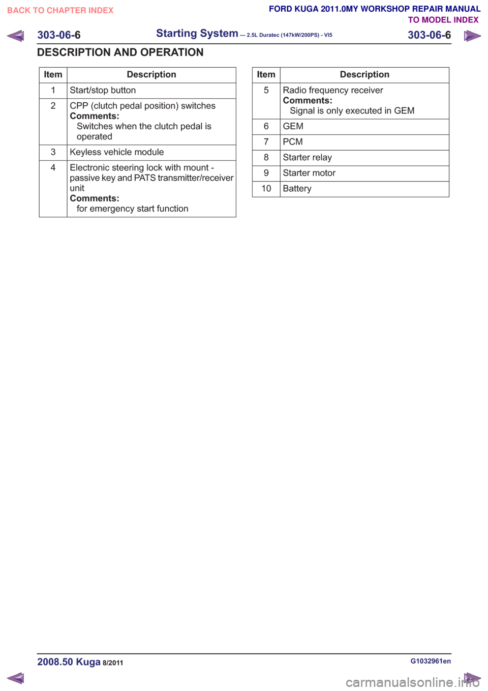
Description
Item
Start/stop button
1
CPP (clutch pedal position) switches
Comments:Switches when the clutch pedal is
operated
2
Keyless vehicle module
3
Electronic steering lock with mount -
passive key and PATS transmitter/receiver
unit
Comments:for emergency start function
4Description
Item
Radio frequency receiver
Comments:Signal is only executed in GEM
5
GEM
6
PCM
7
Starter relay
8
Starter motor
9
Battery
10
G1032961en2008.50 Kuga8/2011
303-06- 6
Starting System— 2.5L Duratec (147kW/200PS) - VI5303-06-
6
DESCRIPTION AND OPERATION
TO MODEL INDEX
BACK TO CHAPTER INDEX
FORD KUGA 2011.0MY WORKSHOP REPAIR MANUAL
Page 1752 of 2057
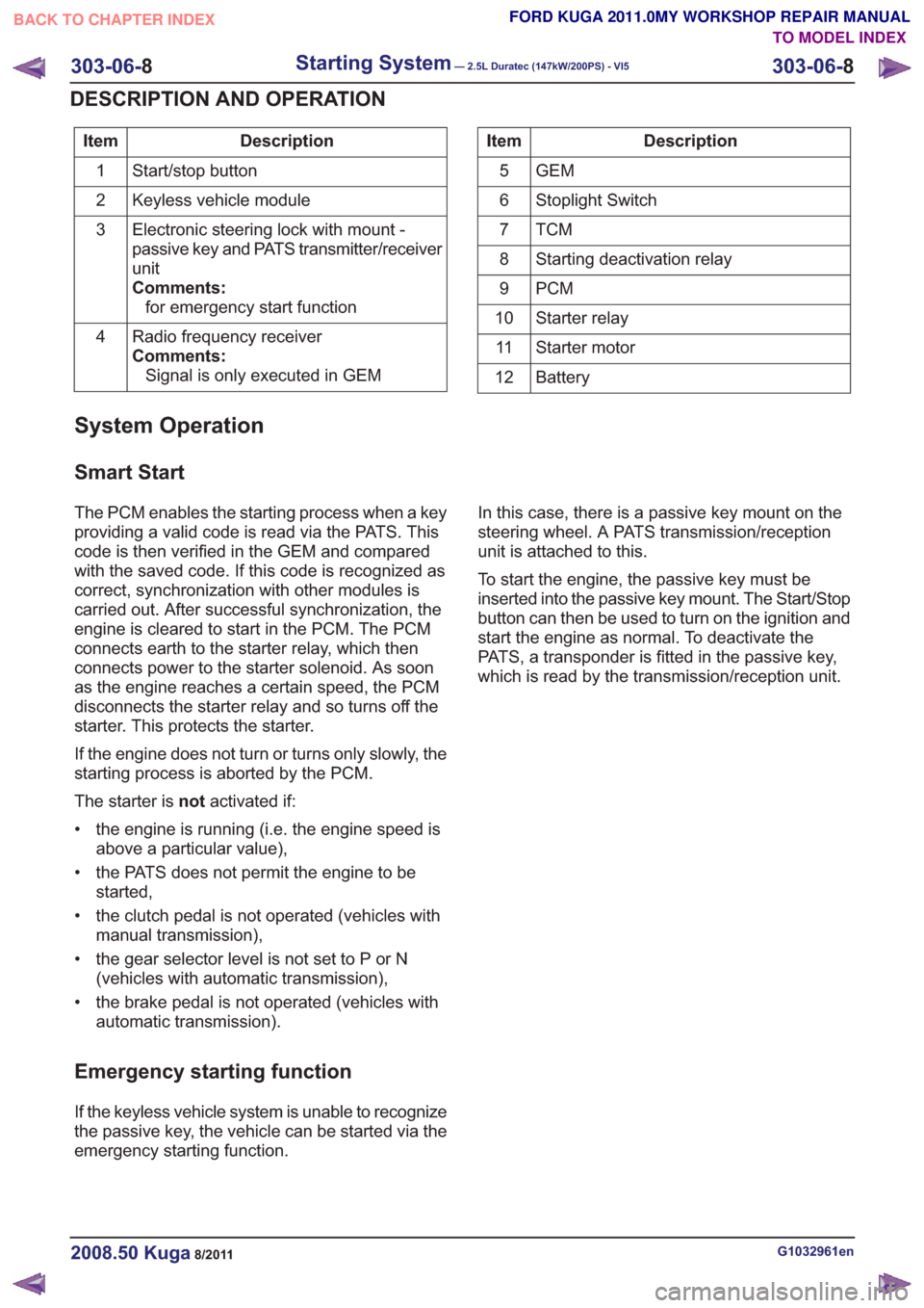
Description
Item
Start/stop button
1
Keyless vehicle module
2
Electronic steering lock with mount -
passive key and PATS transmitter/receiver
unit
Comments:for emergency start function
3
Radio frequency receiver
Comments:Signal is only executed in GEM
4Description
Item
GEM
5
Stoplight Switch
6
TCM7
Starting deactivation relay
8
PCM
9
Starter relay
10
Starter motor
11
Battery
12
System Operation
Smart Start
The PCM enables the starting process when a key
providing a valid code is read via the PATS. This
code is then verified in the GEM and compared
with the saved code. If this code is recognized as
correct, synchronization with other modules is
carried out. After successful synchronization, the
engine is cleared to start in the PCM. The PCM
connects earth to the starter relay, which then
connects power to the starter solenoid. As soon
as the engine reaches a certain speed, the PCM
disconnects the starter relay and so turns off the
starter. This protects the starter.
If the engine does not turn or turns only slowly, the
starting process is aborted by the PCM.
The starter is notactivated if:
• the engine is running (i.e. the engine speed is above a particular value),
• the PATS does not permit the engine to be started,
• the clutch pedal is not operated (vehicles with manual transmission),
• the gear selector level is not set to P or N (vehicles with automatic transmission),
• the brake pedal is not operated (vehicles with automatic transmission).
Emergency starting function
If the keyless vehicle system is unable to recognize
the passive key, the vehicle can be started via the
emergency starting function. In this case, there is a passive key mount on the
steering wheel. A PATS transmission/reception
unit is attached to this.
To start the engine, the passive key must be
inserted into the passive key mount. The Start/Stop
button can then be used to turn on the ignition and
start the engine as normal. To deactivate the
PATS, a transponder is fitted in the passive key,
which is read by the transmission/reception unit.
G1032961en2008.50 Kuga8/2011
303-06-
8
Starting System— 2.5L Duratec (147kW/200PS) - VI5303-06-
8
DESCRIPTION AND OPERATION
TO MODEL INDEX
BACK TO CHAPTER INDEX
FORD KUGA 2011.0MY WORKSHOP REPAIR MANUAL
Page 1755 of 2057
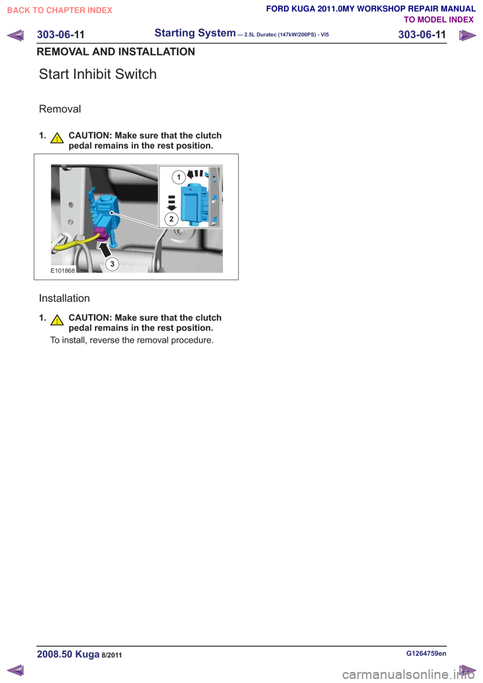
Start Inhibit Switch
Removal
1. CAUTION: Make sure that the clutchpedal remains in the rest position.
1
2
3E101868
Installation
1.CAUTION: Make sure that the clutch
pedal remains in the rest position.
To install, reverse the removal procedure.
G1264759en2008.50 Kuga8/2011
303-06- 11
Starting System— 2.5L Duratec (147kW/200PS) - VI5303-06-
11
REMOVAL AND INSTALLATION
TO MODEL INDEX
BACK TO CHAPTER INDEX
FORD KUGA 2011.0MY WORKSHOP REPAIR MANUAL
Page 1776 of 2057
303-14-34
Exterior aor temperature sensor ........................................................................\
.............
DIAGNOSIS AND TESTING 303-14-35
Electronic Engine Controls ........................................................................\
.........................
303-14-35
Inspection and Verification ........................................................................\
..........................
REMOVAL AND INSTALLATION 303-14-36
(29 232 0)
Camshaft Position (CMP) Sensor ...................................................................
303-14-37
(29 219 0)
Catalyst Monitor Sensor ........................................................................\
.........
303-14-38
(29 230 0)
Crankshaft Position (CKP) Sensor .................................................................
303-14-40
(29 220 0)
Heated Oxygen Sensor (HO2S) .....................................................................
303-14-41
(29 222 0)
Knock Sensor (KS) ........................................................................\
.................
303-14-42
(29 226 0)
Mass Air Flow (MAF) Sensor ........................................................................\
..
303-14-43
(29 200 0)
Powertrain Control Module (PCM) .................................................................
303-14-45
(29 233 0)
Variable Valve Timing (VVT) Oil Control Solenoid ..........................................
303-14-46
(33 502 0)
Brake Pedal Position (BPP) Switch ................................................................
303-14-47
(33 503 0)
Clutch Pedal Position (CPP) Switch ...............................................................
303-14-2
Electronic Engine Controls— 2.5L Duratec (147kW/200PS) - VI5303-14-
2
.
TO MODEL INDEX
BACK TO CHAPTER INDEX
PAGE 2 OF 2
FORD KUGA 2011.0MY WORKSHOP REPAIR MANUAL
Page 1782 of 2057
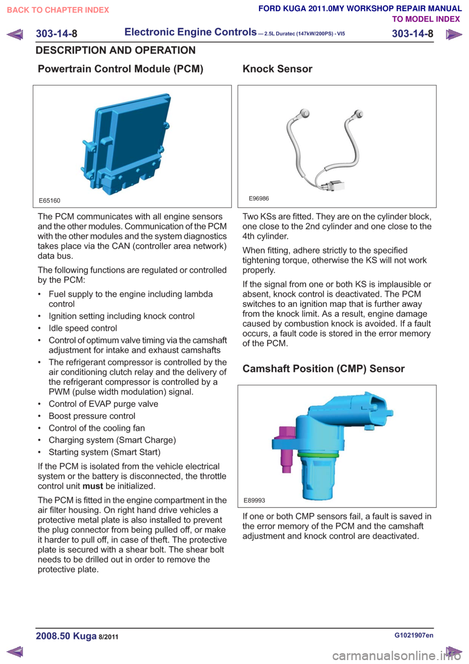
Powertrain Control Module (PCM)
E65160
The PCM communicates with all engine sensors
and the other modules. Communication of the PCM
with the other modules and the system diagnostics
takes place via the CAN (controller area network)
data bus.
The following functions are regulated or controlled
by the PCM:
• Fuel supply to the engine including lambdacontrol
• Ignition setting including knock control
• Idle speed control
• Control of optimum valve timing via the camshaft adjustment for intake and exhaust camshafts
• The refrigerant compressor is controlled by the air conditioning clutch relay and the delivery of
the refrigerant compressor is controlled by a
PWM (pulse width modulation) signal.
• Control of EVAP purge valve
• Boost pressure control
• Control of the cooling fan
• Charging system (Smart Charge)
• Starting system (Smart Start)
If the PCM is isolated from the vehicle electrical
system or the battery is disconnected, the throttle
control unit mustbe initialized.
The PCM is fitted in the engine compartment in the
air filter housing. On right hand drive vehicles a
protective metal plate is also installed to prevent
the plug connector from being pulled off, or make
it harder to pull off, in case of theft. The protective
plate is secured with a shear bolt. The shear bolt
needs to be drilled out in order to remove the
protective plate.
Knock Sensor
E96986
Two KSs are fitted. They are on the cylinder block,
one close to the 2nd cylinder and one close to the
4th cylinder.
When fitting, adhere strictly to the specified
tightening torque, otherwise the KS will not work
properly.
If the signal from one or both KS is implausible or
absent, knock control is deactivated. The PCM
switches to an ignition map that is further away
from the knock limit. As a result, engine damage
caused by combustion knock is avoided. If a fault
occurs, a fault code is stored in the error memory
of the PCM.
Camshaft Position (CMP) Sensor
E89993
If one or both CMP sensors fail, a fault is saved in
the error memory of the PCM and the camshaft
adjustment and knock control are deactivated.
G1021907en2008.50 Kuga8/2011
303-14- 8
Electronic Engine Controls— 2.5L Duratec (147kW/200PS) - VI5303-14-
8
DESCRIPTION AND OPERATION
TO MODEL INDEX
BACK TO CHAPTER INDEX
FORD KUGA 2011.0MY WORKSHOP REPAIR MANUAL