2011 FORD KUGA Clutch switch
[x] Cancel search: Clutch switchPage 1852 of 2057
The TCM detects uphill driving by comparing the
engine load transmitted by the PCM with the engine
speed. If the engine load increases and the engine
speed falls, then the TCM causes the transaxle to
shift to a lower transmission range in order to
increase the traction force.
Downhill driving
The TCM detects downhill driving by comparing
the engine load and engine speed values
transmitted by the PCM with the OSS sensor
signal. In order to prevent overloading of the
vehicle brakes, the TCM causes the transaxle to
shift to a lower transmission range.
Hill-hold function
If the vehicle is stopped on an uphill incline, the
TCM detects this through the faster drop in engine
speed compared with the drop in engine speed
when stopping on the flat. In this situation, the
hydraulics are actuated by the TCM in such a way
that the vehicle is prevented from rolling back. This
function is not used on steep inclines.
If the vehicle is parked on an uphill incline (ignition
switched off), the hill-hold function is not active
when pulling away.
Altitude correction
Lower air density results in reduced engine
performance. In order to compensate for this
operating situation, the TCM changes the shift
points.
Selector lever lock
To prevent the selector lever being accidentally
moved from the P or N position, the vehicle also
has an electrically operated selector lever lock.
This blocks the locking pin in the locking segment
and thus locks the selector lever in the P or N
position.
Shifting from P into another transmission
range
To be able to move the selector lever from P into
another transmission range, the ignition must be
switched on and the brake pedal must be
depressed (stop light switch on). The TCM detects
the position of the brake pedal via the CAN data
bus and the engaged transmission range from the
TR sensor.
The signal is then transferred from the TCM to the
select-shift switch module in order to activate the
solenoid valve in the selector mechanism
assembly.
In position P, the solenoid valve is activated and
the locking pin is pulled in so that the lock button
on the selector lever can be pressed as usual to
engage another transmission range.
In the selector mechanism assembly there is a Hall
sensor which is affected by a permanent magnet
on the gate of the selector mechanism assembly.
If the selector lever is moved from the P position,
both the Hall sensor and the selector lever lock
solenoid are simultaneously deactivated, to prevent
the selector from being kept in the N position.
If the ignition is set to "I" or "0" the solenoid valve
is deactivated. When the selector lever is in the P
position, it is mechanically locked because it has
no voltage.
Shifting from N into another transmission
range
The conditions are the same as for shifting from P
into another transmission range.
However, the lock button on the selector lever must
be pressed to be able to select R or P.
Power flow through the transmission
Clutches and brakes
G1163605en2008.50 Kuga8/2011
307-01-31
Automatic Transmission/Transaxle
— Vehicles With:
5-Speed Automatic Transaxle - AW55 AWD
307-01- 31
DESCRIPTION AND OPERATION
TO MODEL INDEX
BACK TO CHAPTER INDEX
FORD KUGA 2011.0MY WORKSHOP REPAIR MANUAL
Page 1867 of 2057
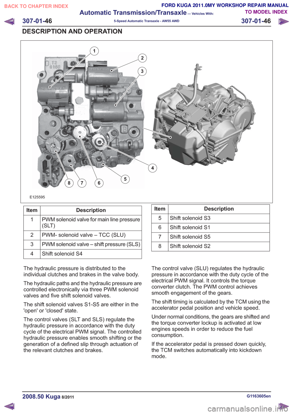
E125595
2
3
4
5678
1
Description
Item
PWM solenoid valve for main line pressure
(SLT)
1
PWM- solenoid valve – TCC (SLU)
2
PWM solenoid valve – shift pressure (SLS)
3
Shift solenoid S4
4Description
Item
Shift solenoid S3
5
Shift solenoid S1
6
Shift solenoid S5
7
Shift solenoid S2
8
The hydraulic pressure is distributed to the
individual clutches and brakes in the valve body.
The hydraulic paths and the hydraulic pressure are
controlled electronically via three PWM solenoid
valves and five shift solenoid valves.
The shift solenoid valves S1-S5 are either in the
'open' or 'closed' state.
The control valves (SLT and SLS) regulate the
hydraulic pressure in accordance with the duty
cycle of the electrical PWM signal. The controlled
hydraulic pressure enables smooth shifting or the
generation of a defined slip through actuation of
the relevant clutches and brakes. The control valve (SLU) regulates the hydraulic
pressure in accordance with the duty cycle of the
electrical PWM signal. It controls the torque
converter clutch. The PWM control achieves
smooth engagement of the gears.
The shift timing is calculated by the TCM using the
accelerator pedal position and vehicle speed.
Under normal conditions, the gears are shifted and
the torque converter lockup is activated at low
engines speeds in order to reduce the fuel
consumption.
If the accelerator pedal is pressed down quickly,
the TCM switches automatically into kickdown
mode.
G1163605en2008.50 Kuga8/2011
307-01-
46
Automatic Transmission/Transaxle
— Vehicles With:
5-Speed Automatic Transaxle - AW55 AWD
307-01- 46
DESCRIPTION AND OPERATION
TO MODEL INDEX
BACK TO CHAPTER INDEX
FORD KUGA 2011.0MY WORKSHOP REPAIR MANUAL
Page 1970 of 2057
Fuel System — Vehicles With: Fuel Additive Tank
General EquipmentFord diagnostic equipment
Principles of Operation
WARNINGS:
This procedure involves fuel additive
handling. Be prepared for fuel additive
spillage at all times and always observe
fuel handling precautions. Failure to follow
these instructions may result in personal
injury.
Eye, hand, ear protection and protective
clothing are required to be worn during
any general service or removal and
installation service procedure of fuel
additive system components. Failure to
follow this instruction may result in
personal injury.
In case of fuel additive fluid contact with
the skin or the eyes, flush immediately with
water for a minimum of 15 minutes and
seek prompt medical attention. Failure to
follow these instructions may result in
personal injury.
If fuel additive fluid is swallowed, call a
physician immediately. Rinse mouth
immediately with water, do not induce
vomiting. Failure to follow these
instructions may result in personal injury.
Always provide adequate ventilation when
working on the fuel additive fluid system
or related components. Failure to follow
these instructions may result in personal
injury.
Do not smoke or carry lighted tobacco or
open flame of any type when working on
or near any fuel related components.
Highly flammable vapors are always
present and may ignite. Failure to follow
these instructions may result in personal
injury.
CAUTION: Make sure the workshop area
in which the vehicle is being worked on is
as clean and as dust free as possible.
Foreign matter from working on clutches,
brakes or from machining or welding
operations can contaminate the fuel
system and may result in later malfunction. The fuel additive system is an on-board system
that allows the injection of an additive at each
refueling operation by the customer. The additive
quantity is proportional to the fuel quantity that has
been added. The fuel additive system module
controls the amount of additive fluid entering the
fuel tank at each refueling, A switch mounted on
the fuel filler flap is used to detect the start of the
refueling event and the fuel gauge that is mounted
within the fuel tank informs the fuel additive tank
module the quantity of actual fuel added.
Inspection and Verification
1. Verify the customer concern.
2. Visually inspect for obvious signs of leakage
and mechanical or electrical damage.
Visual Inspection Chart
Electrical
Mechanical
– Fuse(s)
– Fuel filler switch andmagnet
– Wiring harness(s)
– Electrical connector(s)
– Fuel additive system module
– Fuel additive tank module
– Instrument cluster
– Powertrain Control Module (PCM)
– Fuel level sensor
– Fuel additive tank
– Fuel additive tank
line(s)
– Fuel additive tank pipe(s)
– Fuel additive tank connector(s)
– Fuel tank filler cap
3. If an obvious cause for an observed or reported concern is found, correct the cause (if possible)
before proceeding to the next step
4. If the cause is not visually evident, REFER to the Ford diagnostic equipment.
G1080718en2008.50 Kuga8/2011
310-00- 2
Fuel System - General Information
310-00- 2
DIAGNOSIS AND TESTING
TO MODEL INDEX
BACK TO CHAPTER INDEX
FORD KUGA 2011.0MY WORKSHOP REPAIR MANUAL
Page 2007 of 2057
Description
Item
PCM
8
Throttle body
Comments:Contains the TP (throttle position) sensor
9
The APP (accelerator pedal position)
sensor.
10Description
Item
CPP (clutch pedal position) switch
Comments:Vehicles with manual transaxle.
11
BPP (brake pedal position) switch
12
Reverse gear solenoid
Comments:Vehicles with manual transaxle.
13
System Operation
Speed Control
Cruise control is integrated into PCM and
intervenes in engine management to automatically
keep to the target speed selected by the driver.
When the system is active, the vehicle can be
accelerated or decelerated without the accelerator
pedal being pressed. Cruise control is operated
using the control switch units on the steering wheel.
The PCM controls the throttle to achieve this. The
ABS module supplies the VSS signal for this.
On vehicles with automatic transmission, the TCM
receives a notification via the CAN (controller area
network) bus that cruise control is active. The TCM
then controls the transmission based on special
engine maps.
Cruise control recognizes three operating modes:
• "OFF": Control is switched off.
• "STANDBY": Control is switched on but not
active. The speed of the vehicle is not regulated
by the cruise control.
• "ACTIVE": Control is switched on and active. Cruise control adjusts the vehicle speed to the
stored or desired target speed.
Every time the engine is started, cruise control is
in the "OFF" mode. In this mode, only the "ON"
button is operable.
Cruise control is initially set to "STANDBY" mode
when the "ON" button is pressed. The green cruise
control indicator lamp in the instrument cluster
lights up. There is no target speed saved.
Cruise control can only be set to "STANDBY" mode
under the following conditions:
• Engine speed is between idle speed and maximum permissible speed. Cruise control can only be changed into "ACTIVE"
mode under the following conditions:
• 2nd - 6th gear engaged.
• Engine speed between idle speed and maximum
permissible speed.
• Vehicle speed at least 40 km/h.
Pressing the "SET+" or "SET-" button activates
cruise control ("ACTIVE" mode). The green "Cruise
control" indicator lamp in the instrument cluster
lights up. The current vehicle speed is saved as
the target.
In "ACTIVE" mode the "OFF", "SET+", "SET-" and
"RES" buttons are active. If the "RES" button is
pressed again, control is suspended. The "RES"
button has a dual function and is used to resume
and suspend the cruise control.
Tapping the "SET+" button (for less than 640 ms)
increases the target speed by 1 km/h at a time.
Holding down the "SET+" button (for longer than
640 ms) increases the target speed until the button
is released. If the button is not released, cruise
control accelerates the vehicle up to the maximum
permissible vehicle speed (200 km/h) or up to the
vehicle's maximum speed (whichever speed is
lower). Tapping the "SET-" button (for less than
640 ms) reduces the target speed by 1 km/h at a
time. When the the "SET-" button is held down, the
control reduces the target speed until the button is
released. If the "SET-" button is held down until
the minimum speed of 40 km/h is reached, cruise
control switches to "STANDBY" mode.
Cruise control is put into "STANDBY" mode when
the "RES" button is pressed. Control to the stored
target speed can be started again by pressing the
"RES" button again. If the "SET+" or "SET-" button
is pressed while the "RES" function is being
performed (control to saved target speed), cruise
G1044191en2008.50 Kuga8/2011
310-03- 4
Speed Control
310-03- 4
DESCRIPTION AND OPERATION
TO MODEL INDEX
BACK TO CHAPTER INDEX
FORD KUGA 2011.0MY WORKSHOP REPAIR MANUAL
Page 2008 of 2057
control saves the current speed as the target
speed.
Cruise control goes into STANDBY mode in the
following situations:
• Operation of the brake pedal
• Operation of the clutch pedal
• Operation of the parking brake
• If the driver operates the accelerator pedal andthe saved target speed is subsequently
exceeded for more than 5 minutes.
• Pressing any cruise control button for more than 2 minutes
• Intervention by the traction control or electronic stability program (for longer than 40 ms)
• Shifting of the gear selector lever to the "N" position (vehicles with automatic transmission
only)
• Minimum speed falls below 40 km/h.
• Occurrence of particular DTC (diagnostic trouble code)
• faulty signal from the backup lamp switch
Cruise control is switched off when the "OFF"
button is pressed.
If the accelerator pedal is pressed down, the
vehicle speed increases. As soon as the pedal is
released, the speed falls to the saved target value. The following components supply the signals
needed by the cruise control:
• The APP sensor.
– The APP sensor identifies the currentposition of the accelerator pedal and sends
a PWM (pulse width modulation) signal to
the PCM and an analog DC (direct current)
signal to the GEM.
– If one or both of the APP sensors fails, a fault is stored in the PCM fault memory and cruise
control cannot be activated.
• BPP switch – The BPP switch tells the PCM whether thevehicle is being braked. In its rest state the
switch is closed and sends an earth signal
to the GEM. This signal is sent via the CAN
to the PCM.
– The brake light switch is likewise connected to the GEM and is opened in the rest state.
When the vehicle is braked, the brake light
switch sends a signal to the GEM. This
compares the signals from the BPP switch
and the brake light switch. If a discrepancy
occurs, a fault is stored in the error memory
of the GEM. Cruise control cannot be
activated.
• CPP switch – The CPP switch sends a ground signal to theGEM as soon as the clutch is operated. This
signal is passed on by the GEM via the CAN
bus to the PCM. This then supplies the signal
to the cruise control.
– If the CPP switch is incorrectly installed or set, cruise control cannot be activated.
• Wheel speed sensors – The wheel speed sensors record the speedof all the wheels. The recorded speed values
are sent to the ABS module via a hard-wired
connection. The ABS module calculates a
vehicle speed signal (VS signal) from the
speed values and the wheel diameter. This
vehicle speed signal is transferred via the
CAN bus to the PCM and supplied to the
cruise control. If the vehicle speed signal is
faulty, cruise control cannot be activated.
G1044191en2008.50 Kuga8/2011
310-03- 5
Speed Control
310-03- 5
DESCRIPTION AND OPERATION
TO MODEL INDEX
BACK TO CHAPTER INDEX
FORD KUGA 2011.0MY WORKSHOP REPAIR MANUAL
Page 2010 of 2057
Speed Control
Inspection and Verification
1. Verify the customer concern by operating thesystem.
2. Visually inspect for obvious signs of mechanical or electrical damage.
Visual Inspection Chart
Electrical
Mechanical
– Fuse(s)
– Connections
– Wiring harness
– Clockspring
– Loose or corrodedelectrical
connector(s)
– Speed control switch
– Brake pedal position (BPP) deactivation
switch
– Clutch pedal posi- tion (CPP) deactiva-
tion Switch
– Powertrain control module (PCM)
– Central junction box (CJB)
– Brake pedal
– Clutch pedal
3. NOTE: Not all passenger junction box (PJB) variants support the speed control system.
NOTE: If the PJB is configured for speed control
disable, speed control operation is not transmitted,
no Diagnostic Trouble Codes (DTCs) are
generated.
If an obvious cause for an observed or reported
concern is found, correct the cause (if possible)
before proceeding to the next step.
4. If the cause is not visually evident, verify the symptom and refer to the diagnostic tab within
the Ford approved diagnostic tool.
G1054908en2008.50 Kuga8/2011
310-03- 7
Speed Control
310-03- 7
DIAGNOSIS AND TESTING
TO MODEL INDEX
BACK TO CHAPTER INDEX
FORD KUGA 2011.0MY WORKSHOP REPAIR MANUAL
Page 2015 of 2057
• The refrigerant line between the fixed orificetube and the evaporator must be cold from the
point where the fixed orifice tube is installed.
Depending on the weather, the refrigerant line
may also have ice on its surface.
• The refrigerant line between the evaporator and the A/C compressor including the dehydrator
must be cold.
Evaporator outlet line temperature test
To test the power of the A/C system, the
temperature at the evaporator outlet line must be
measured. To do this, the following preconditions
must be met:
• Open all windows.
• Set the air distribution to the defrost/dashboardposition and open all the ventilation nozzles.
• DO NOT switch on recirculated air.
• Select lowest blower switch setting.
• Select lowest temperature setting.
NOTE: The temperature measurement cannot be
done with a thermometer which makes no contact.
The surface reflection from the metal line may
cause incorrect readings.
Connect the temperature sensor (Fluke 80 PK-8)
to the outlet line of the evaporator. Locate the
temperature sensor as close as possible to the
evaporator. Connect the temperature sensor to the
multimeter.
Start the engine and allow it to run at idle speed
for several minutes.
Switch on the A/C.
After three minutes, measure the surface
temperature of the evaporator outlet line.
If the temperature measured is 4° C or lower, the
A/C system is OK. If the temperature is higher, the
A/C system may be under-filled. For further
information, refer to
REFER to: Air Conditioning (A/C) System
Recovery, Evacuation and Charging (412-00
Climate Control System - General Information,
General Procedures).
Frequent faults and their causes
If the cooling power of the A/C system is not
adequate, make certain that the temperature
control flap(s) is/are operating correctly. • No or poor cooling performance:
– Blockage or narrowing of a refrigerant line orin the dehydrator. The location of the
blockage or narrowing can easily be located
by temperature comparisons at the
refrigerant lines and the dehydrator. The
blockage or restriction is located at the point
where the temperature difference is
identified. Note: A temperature difference
in the area of the fixed orifice tube is
normal. If the location of the blockage or
narrowing is found, check the corresponding
component and renew as applicable.
• Sudden drop in cooling performance (after the air conditioning has been switched off for
approx. 5 minutes, the cooling performance
returns to normal):
– The cause is an iced-up fixed orifice tubebecause of moisture in the refrigerant circuit.
In order to ensure that moisture is completely
removed from the refrigerant circuit, the
dehydrator should be renewed and the
evacuation time should be extended to 2-3
hours. For further information
REFER to: Air Conditioning (A/C) System
Recovery, Evacuation and Charging
(412-00 Climate Control System - General
Information, General Procedures).
Sequence of A/C Request Signal
NOTE: The electronic automatic temperature
control (EATC) module is integrated into the air
conditioning control assembly.
NOTE: The generic electronic module (GEM) is
an integral part of the central junction box (CJB).
After actuating the A/C ON/OFF switch integrated
into the A/C control assembly, an A/C request
signal is sent from the A/C control assembly
(vehicles with EATC: EATC module) to the GEM.
From there, the signal is sent to the instrument
cluster via the MS-CAN bus. A gateway is installed
in the instrument cluster, which establishes the
connection between the MS-CAN bus and the
HS-CAN bus.
After the signal has been converted in the gateway,
it is relayed to the powertrain control module (PCM)
via the HS-CAN bus. Once all the required
parameters have been met, the PCM switches on
the refrigerant compressor and thus the A/C system
via the A/C clutch relay.
G1055878en2008.50 Kuga8/2011
412-00- 4
Climate Control System - General Information
412-00- 4
DIAGNOSIS AND TESTING
TO MODEL INDEX
BACK TO CHAPTER INDEX
FORD KUGA 2011.0MY WORKSHOP REPAIR MANUAL
Page 2028 of 2057
SECTION 412-01 Climate Control
VEHICLE APPLICATION:2008.50 Kuga
PA G E
CONTENTS
SPECIFICATIONS
412-01-3
Specifications ........................................................................\
..............................................
DESCRIPTION AND OPERATION 412-01-4
Climate Control (Component Location) ........................................................................\
......
412-01-10
Climate Control (Overview) ........................................................................\
........................
412-01-10
Pollen filter ........................................................................\
..................................................
412-01-10
Heat exchanger ........................................................................\
..........................................
412-01-10
Evaporator assembly ........................................................................\
..................................
412-01-10
Blower motor ........................................................................\
..............................................
412-01-11
Fault Memory Interrogation without diagnostics unit - vehicles with automatic temperature
control ........................................................................\
.......................................................
412-01-11
Switch over from Celsius to Fahrenheit ........................................................................\
......
412-01-12
Climate Control (System Operation and Component Description) .....................................
412-01-12
System Diagram ........................................................................\
.........................................
412-01-19
System Operation ........................................................................\
.......................................
412-01-19
Climate control housing ........................................................................\
..........................
412-01-22
Climate control ........................................................................\
........................................
412-01-24
Component Description ........................................................................\
..............................
412-01-24
Air conditioning compressor ........................................................................\
...................
412-01-24
Pollen filter ........................................................................\
..............................................
412-01-24
Control assembly, climate control - vehicles with manual temperature control ..............
412-01-25
Control assembly, climate control - vehicles with automatic temperature control ...........
412-01-25
Control assembly, climate control - vehicles with DVD navigation system with a touch
screen........................................................................\
................................................... 412-01-25
Climate control module - vehicles with DVD navigation system with a touch screen.....
412-01-25
Sun sensor - vehicles with automatic temperature control .............................................
412-01-26
In-vehicle temperature sensor ........................................................................\
................
412-01-26
Ambient temperature sensor ........................................................................\
..................
412-01-26
Blower motor ........................................................................\
...........................................
412-01-26
Blower control module - vehicles equipped with automatic temperature control ............
REMOVAL AND INSTALLATION 412-01-28
(34 626 4)
Air Conditioning (A/C) Compressor — 2.5L Duratec (147kW/200PS) - VI5 ....
412-01-29
Air Conditioning (A/C) Compressor to Condenser Discharge Line .....................................
412-01-30
Air Conditioning (A/C) Compressor to Condenser Discharge Line — 2.5L Duratec
(147kW/200PS) - VI5 ........................................................................\
................................
412-01-31
Condenser ........................................................................\
..................................................
412-01-35
Clutch and Clutch Field Coil........................................................................\
.......................
412-01-36
Pollen Filter — RHD........................................................................\
...................................
412-01-37
(34
374 0)
Blower Motor — RHD ........................................................................\
.............
412-01-40
(34 382 0)
Blower Motor Resistor — Vehicles With: Manual Temperature Control, RHD .
412-01-41
(34 382 0)
Blower Motor Resistor — Vehicles With: Dual Automatic Temperature
Control ........................................................................\
..................................
412-01- 1
Climate Control
412-01- 1
.
TO MODEL INDEX
BACK TO CHAPTER INDEX
PAGE 1 OF 2 FORD KUGA 2011.0MY WORKSHOP REPAIR MANUAL