2011 FORD KUGA High pressure pump
[x] Cancel search: High pressure pumpPage 87 of 2057

Action
Possible Sources
Symptom
CHECK the installation and
potential damage of the floor
seal.
Floor seal.
NOTE:
Engine speed at idle
turning the steering wheel slowly
lock to lock.
Power steering system hiss noise
– a high frequency, continuous
rush or swish noise like escaping
air from a balloon. Hiss occurs
while turning between the
steering lock stops, all steering
angles. Noise does not change
with engine rpm and is worse at
high operating temperatures. Certain amount of noise level
acceptable, not a safety critical
item.
Power steering gear valve
design.
Certain amount of noise level
acceptable, not a safety critical
item.
Power steering system hydraulic
design.
Certain amount of noise level
acceptable, not a safety critical
item.
Power steering pump pressure
relief valve.
NOTE:
Engine speed at idle
holding the steering wheel
against a steering lock for three
seconds. Do not hold for more
than five seconds.
Power steering system hiss noise
– a continuous noise like
escaping air occurs while holding
the steering against a steering
lock stop.
Power Steering Lock Stop Impact Knock
Noise
Test Condition
Listen for steering knock noise with the engine
speed at idle in the following test conditions (noise
also apparent with engine off). 1. Turn the steering wheel to the left-hand and
right-hand steering locks and listen for the
impact noise.
Action
Possible Sources
Symptom
Certain amount of noise level
acceptable, not a safety critical
item.
Power steering gear mechanical
noise, metal to metal at end of
steering travel.
Power steering system knock
noise – a heavy loud sound like
a knock on a door that occurs in
parking condition when hitting the
lock stop.
Power Steering Mechanical Knock Noise
(PAS off)
Test Condition
Listen for steering knock noise with the engine off
in the following test conditions (no power assist). 1. Turn the steering wheel 90 degrees to the right,
hold and then quickly release.
2. Turn the steering wheel 90 degrees to the left, hold and then quickly release.
G37349en2008.50 Kuga8/2011
100-04- 9
Noise, Vibration and Harshness
100-04- 9
DIAGNOSIS AND TESTING
TO MODEL INDEX
BACK TO CHAPTER INDEX
FORD KUGA 2011.0MY WORKSHOP REPAIR MANUAL
Page 89 of 2057

Action
Possible Sources
Symptom
Certain amount of noise level
acceptable, not a safety critical
item.
Power steering return lines.
Power steering system knock/
clonk noise – sounds almost
identical to column knock that
occurs when driving and
cornering over cobbled stones or
rough roads. Noise may appear
to emanate from a location closer
to the floor than that for column
knock (Sounds like metallic noise
but is created by pressure
impulse in gear and return line –
similar to a sound like quickly
turning off a water tap). Certain amount of noise level
acceptable, not a safety critical
item.
High power assist gain of power
steering gear valve (steering gear
design - no quality issue).
Certain amount of noise level
acceptable, not a safety critical
item.
High power steering pump flow
rate (by design).
Power Steering Column Knock Noise
Test Condition
Listen for steering knock noise in the following test
conditions with windows closed. 1. Drive over cobbled stones at low speed 16-40
km/h (10-25 mph) with and without steering
input carefully listening for knock sounds.
2. Drive over straight tar strips, road rails or 25 mm tall harshness strips at low speed 16-40 km/h
(10-25 mph) both driving straight and with
moderate cornering.
Action
Possible Sources
Symptom
CHECK the steering column
retaining bolts and attachments
to the steering column and
secure if necessary.
Steering column or steering
column shaft.
Power steering system column
knock noise – a loose sounding
rattle or vibration coming from the
column. Noticeable by hearing
and touch. Check steering column and
intermediate shaft for free play or
loose components.
REFER to:
Steering System (211-
00 Steering System - General
Information, Diagnosis and
Testing).
Power Steering Toc-Toc Noise
Test Condition
Listen for steering toc-toc noise with the engine
speed at idle and the vehicle parked, automatic
transmission in "P" (PARK) or manual transmission
in neutral and the windows closed. 1. Turn the steering wheel from left to right abruptly
changing direction.
2. Drive the vehicle for low speed parking manoeuvres constantly changing steering
direction.
G37349en2008.50 Kuga8/2011
100-04- 11
Noise, Vibration and Harshness
100-04- 11
DIAGNOSIS AND TESTING
TO MODEL INDEX
BACK TO CHAPTER INDEX
FORD KUGA 2011.0MY WORKSHOP REPAIR MANUAL
Page 187 of 2057

Description
Item
Instrument Cluster
1
PCM (powertrain control module)
2
EHPS (electro-hydraulic power steering)
control module
3
Audio unit
4
GEM (generic electronic module)
5
RCM (restraints control module)
6
PATS transceiver
7 Description
Item
Steering wheel lock module
8
Left-hand steering column switch
9
Fuel level sensor
10
Washer water level warning lamp switch
11
Accelerator pedal position sensor
12
CPP (clutch pedal position) sensor/BPP
(brake pedal position) sensor
13
Lighting control switch
14
System Operation
Instrument Cluster
The instrument cluster contains analog displays
as well as warning and control lamps for displaying
the system status; in addiiton, there is an LCD
indicator field for driver information.
The instrument cluster receives the following
signals from the PCM via the high speed CAN
(controller area network) Bus (HS-CAN):
• Vehicle speed – The PCM receives the necessary signalsfrom the ABS (anti-lock brake system) wheel
sensors from the ABS control unit on the
HS-CAN.
• Engine Coolant Temperature
• Engine oil pressure.
• Engine speed
The instrument cluster receives the following
signals from the GEM via the medium speed CAN
Bus (MS-CAN):
• Ambient temperature
• Brake fluid level
• Handbrake control
• Door latch control
• Liftgate latch control
• High beam control
• Headlamp flasher control
• Direction indicator control
The fuel level signal is sent by the two fuel level
sensors in the fuel pumps in the semitrailer tank,
which is wired to the instrument cluster. The
sensors are connected in series, and the total
resistance is determined from the two individual resistors. The instrument cluster converts the raw
fuel level signal into a damped fuel level value.
The odometer shows the total distance travelled
by the vehicle and is based on the same signal as
is processed for the daily mileage counter. The
value is recorded by the instrument cluster and
stored in a protected EEPROM (Electronically
Erasable Programmable Read Only Memory) area.
This area is a memory protected against
manipulation. If the instrument cluster detects an
error in this memory area, e.g. through damage,
the driver is notified with the "Odometer error"
message.
Message center
The message center is operated using the left-hand
switch on the steering column.
The SET/RESET button is activated to select a
submenu and change the settings. If signal tones
have been activated, a short acoustic signal will
sound each time a button is pressed.
By turning the rotary switch, the different menu
displays can be scrolled through or a setting
selected.
In this display, the navigation system can also
display direction and distance information.
In addition, safety and warning messages can be
displayed in this system, such as "Coolant
overheating", "Engine system error" or "Washer
fluid level too low". In addition to a safety message,
a general warning light (red/yellow) lights up.
G1030770en
2008.50 Kuga 8/2011 413-01-4
Instrument Cluster
413-01-4
DESCRIPTION AND OPERATIONTO MODEL INDEX
BACK TO CHAPTER INDEX
FORD KUGA 2011.0MY WORKSHOP REPAIR MANUAL
Page 1252 of 2057
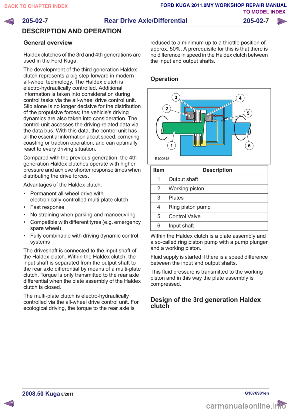
General overview
Haldex clutches of the 3rd and 4th generations are
used in the Ford Kuga.
The development of the third generation Haldex
clutch represents a big step forward in modern
all-wheel technology. The Haldex clutch is
electro-hydraulically controlled. Additional
information is taken into consideration during
control tasks via the all-wheel drive control unit.
Slip alone is no longer decisive for the distribution
of the propulsive forces; the vehicle's driving
dynamics are also taken into consideration. The
control unit accesses the driving-related data via
the data bus. With this data, the control unit has
all the essential information about speed, cornering,
coasting or traction operation, and can optimally
react to every driving situation.
Compared with the previous generation, the 4th
generation Haldex clutches operate with higher
pressure and achieve shorter response times when
distributing the drive forces.
Advantages of the Haldex clutch:
• Permanent all-wheel drive withelectronically-controlled multi-plate clutch
• Fast response
• No straining when parking and manoeuvring
• Compatible with different tyres (e.g. emergency spare wheel)
• Fully combinable with driving dynamic control systems
The driveshaft is connected to the input shaft of
the Haldex clutch. Within the Haldex clutch, the
input shaft is separated from the output shaft to
the rear axle differential by means of a multi-plate
clutch. Torque is only transmitted to the rear axle
differential when the plate assembly of the Haldex
clutch is closed.
The multi-plate clutch is electro-hydraulically
controlled via the all-wheel drive control unit. For
ecological driving, the torque to the rear axle is reduced to a minimum up to a throttle position of
approx. 50%. A prerequisite for this is that there is
no difference in speed in the Haldex clutch between
the input and output shafts.
Operation
E100645
16
3
25
4
Description
Item
Output shaft
1
Working piston
2
Plates
3
Ring piston pump
4
Control Valve
5
Input shaft
6
Within the Haldex clutch is a plate assembly and
a so-called ring piston pump with a pump plunger
and a working piston.
Fluid supply is started if there is a speed difference
between the input and output shafts.
This fluid pressure is transmitted to the working
piston and in this way the plate assembly is
compressed.
Design of the 3rd generation Haldex
clutch
G1076981en2008.50 Kuga8/2011
205-02- 7
Rear Drive Axle/Differential
205-02- 7
DESCRIPTION AND OPERATION
TO MODEL INDEX
BACK TO CHAPTER INDEX
FORD KUGA 2011.0MY WORKSHOP REPAIR MANUAL
Page 1253 of 2057
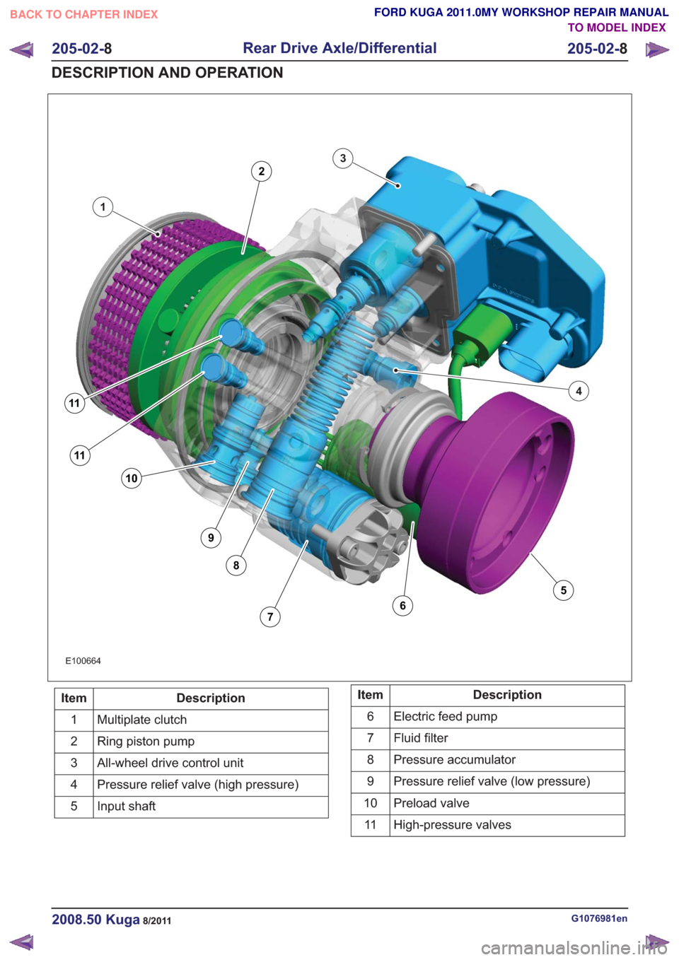
E100664
1
3
4
11
11
10
9
8
76
5
2
Description
Item
Multiplate clutch
1
Ring piston pump
2
All-wheel drive control unit
3
Pressure relief valve (high pressure)
4
Input shaft
5Description
Item
Electric feed pump
6
Fluid filter
7
Pressure accumulator
8
Pressure relief valve (low pressure)
9
Preload valve
10
High-pressure valves
11
G1076981en2008.50 Kuga8/2011
205-02- 8
Rear Drive Axle/Differential
205-02- 8
DESCRIPTION AND OPERATION
TO MODEL INDEX
BACK TO CHAPTER INDEX
FORD KUGA 2011.0MY WORKSHOP REPAIR MANUAL
Page 1255 of 2057
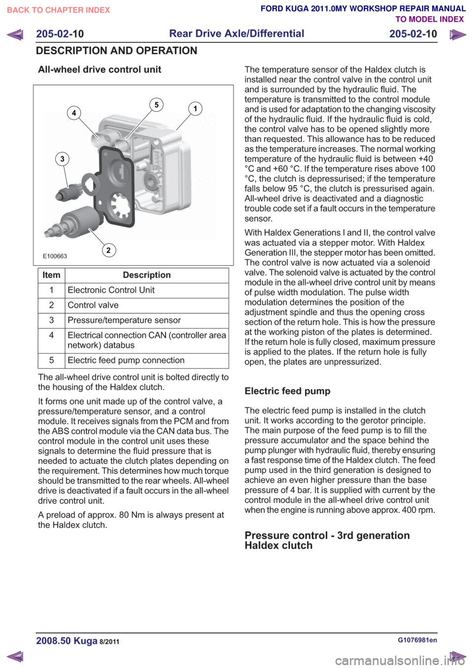
All-wheel drive control unit
E100663
14
3
2
5
Description
Item
Electronic Control Unit
1
Control valve
2
Pressure/temperature sensor
3
Electrical connection CAN (controller area
network) databus
4
Electric feed pump connection
5
The all-wheel drive control unit is bolted directly to
the housing of the Haldex clutch.
It forms one unit made up of the control valve, a
pressure/temperature sensor, and a control
module. It receives signals from the PCM and from
the ABS control module via the CAN data bus. The
control module in the control unit uses these
signals to determine the fluid pressure that is
needed to actuate the clutch plates depending on
the requirement. This determines how much torque
should be transmitted to the rear wheels. All-wheel
drive is deactivated if a fault occurs in the all-wheel
drive control unit.
A preload of approx. 80 Nm is always present at
the Haldex clutch. The temperature sensor of the Haldex clutch is
installed near the control valve in the control unit
and is surrounded by the hydraulic fluid. The
temperature is transmitted to the control module
and is used for adaptation to the changing viscosity
of the hydraulic fluid. If the hydraulic fluid is cold,
the control valve has to be opened slightly more
than requested. This allowance has to be reduced
as the temperature increases. The normal working
temperature of the hydraulic fluid is between +40
°C and +60 °C. If the temperature rises above 100
°C, the clutch is depressurised; if the temperature
falls below 95 °C, the clutch is pressurised again.
All-wheel drive is deactivated and a diagnostic
trouble code set if a fault occurs in the temperature
sensor.
With Haldex Generations I and II, the control valve
was actuated via a stepper motor. With Haldex
Generation III, the stepper motor has been omitted.
The control valve is now actuated via a solenoid
valve. The solenoid valve is actuated by the control
module in the all-wheel drive control unit by means
of pulse width modulation. The pulse width
modulation determines the position of the
adjustment spindle and thus the opening cross
section of the return hole. This is how the pressure
at the working piston of the plates is determined.
If the return hole is fully closed, maximum pressure
is applied to the plates. If the return hole is fully
open, the plates are unpressurized.
Electric feed pump
The electric feed pump is installed in the clutch
unit. It works according to the gerotor principle.
The main purpose of the feed pump is to fill the
pressure accumulator and the space behind the
pump plunger with hydraulic fluid, thereby ensuring
a fast response time of the Haldex clutch. The feed
pump used in the third generation is designed to
achieve an even higher pressure than the base
pressure of 4 bar. It is supplied with current by the
control module in the all-wheel drive control unit
when the engine is running above approx. 400 rpm.
Pressure control - 3rd generation
Haldex clutch
G1076981en2008.50 Kuga8/2011
205-02-
10
Rear Drive Axle/Differential
205-02- 10
DESCRIPTION AND OPERATION
TO MODEL INDEX
BACK TO CHAPTER INDEX
FORD KUGA 2011.0MY WORKSHOP REPAIR MANUAL
Page 1256 of 2057
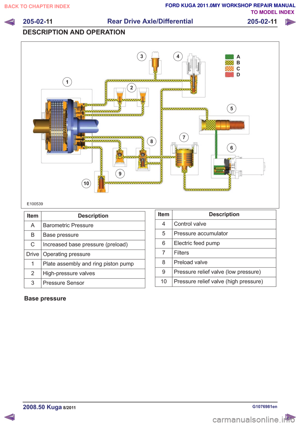
E100539
34
2
1
9
8
10
7
6
5A
B
C
D
Description
Item
Barometric Pressure
A
Base pressure
B
Increased base pressure (preload)
C
Operating pressure
Drive
Plate assembly and ring piston pump
1
High-pressure valves
2
Pressure Sensor
3Description
Item
Control valve
4
Pressure accumulator
5
Electric feed pump
6
Filters7
Preload valve
8
Pressure relief valve (low pressure)
9
Pressure relief valve (high pressure)
10
Base pressure
G1076981en2008.50 Kuga8/2011
205-02- 11
Rear Drive Axle/Differential
205-02- 11
DESCRIPTION AND OPERATION
TO MODEL INDEX
BACK TO CHAPTER INDEX
FORD KUGA 2011.0MY WORKSHOP REPAIR MANUAL
Page 1258 of 2057
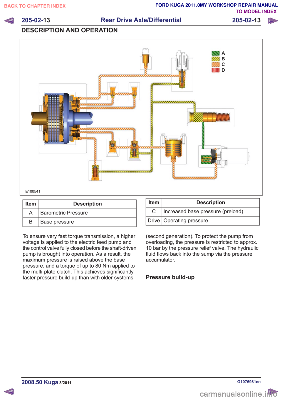
E100541
Description
Item
Barometric Pressure
A
Base pressure
BDescription
Item
Increased base pressure (preload)
C
Operating pressure
Drive
To ensure very fast torque transmission, a higher
voltage is applied to the electric feed pump and
the control valve fully closed before the shaft-driven
pump is brought into operation. As a result, the
maximum pressure is raised above the base
pressure, and a torque of up to 80 Nm applied to
the multi-plate clutch. This achieves significantly
faster pressure build-up than with older systems (second generation). To protect the pump from
overloading, the pressure is restricted to approx.
10 bar by the pressure relief valve. The hydraulic
fluid flows back into the sump via the pressure
accumulator.
Pressure build-up
G1076981en2008.50 Kuga8/2011
205-02-
13
Rear Drive Axle/Differential
205-02- 13
DESCRIPTION AND OPERATION
TO MODEL INDEX
BACK TO CHAPTER INDEX
FORD KUGA 2011.0MY WORKSHOP REPAIR MANUAL