2011 FORD KUGA High pressure pump
[x] Cancel search: High pressure pumpPage 1260 of 2057
1
2
3
4
E115887
Description
Item
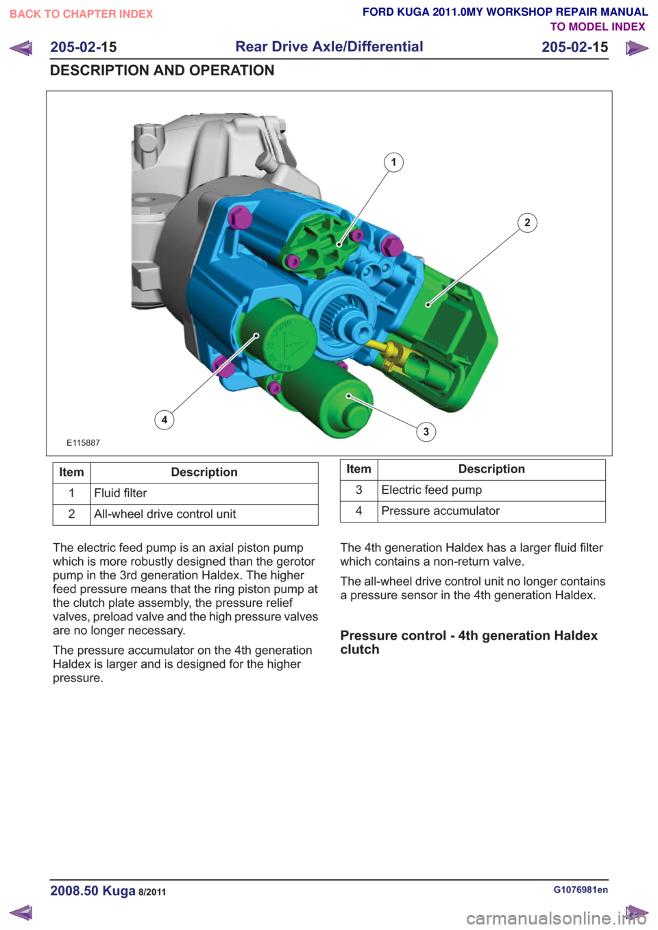
Fluid filter
1
All-wheel drive control unit
2Description
Item
Electric feed pump
3
Pressure accumulator
4
The electric feed pump is an axial piston pump
which is more robustly designed than the gerotor
pump in the 3rd generation Haldex. The higher
feed pressure means that the ring piston pump at
the clutch plate assembly, the pressure relief
valves, preload valve and the high pressure valves
are no longer necessary.
The pressure accumulator on the 4th generation
Haldex is larger and is designed for the higher
pressure. The 4th generation Haldex has a larger fluid filter
which contains a non-return valve.
The all-wheel drive control unit no longer contains
a pressure sensor in the 4th generation Haldex.
Pressure control - 4th generation Haldex
clutch
G1076981en2008.50 Kuga8/2011
205-02-
15
Rear Drive Axle/Differential
205-02- 15
DESCRIPTION AND OPERATION
TO MODEL INDEX
BACK TO CHAPTER INDEX
FORD KUGA 2011.0MY WORKSHOP REPAIR MANUAL
Page 1465 of 2057
Description
Item
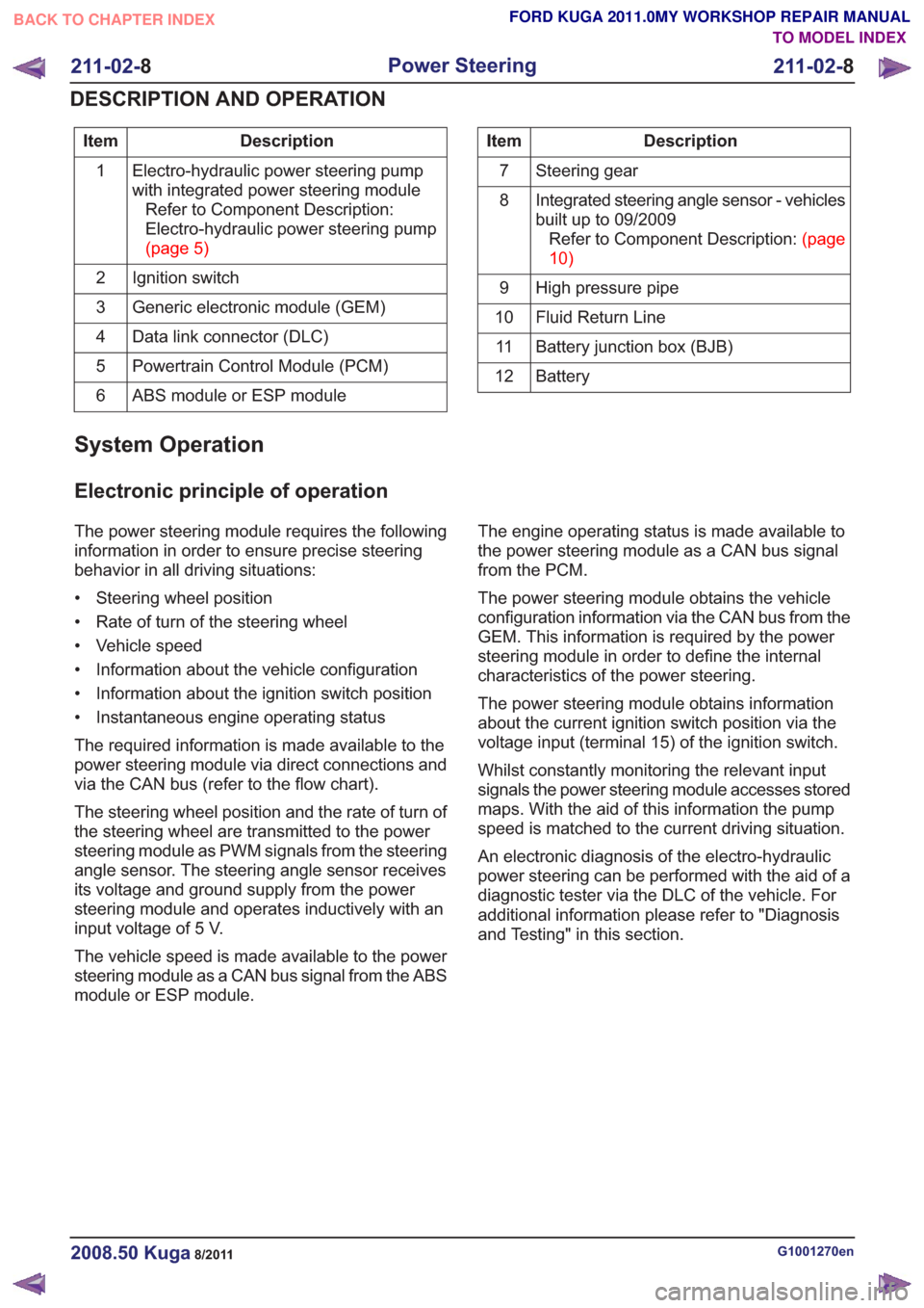
Electro-hydraulic power steering pump
with integrated power steering moduleRefer to Component Description:
Electro-hydraulic power steering pump
(page5)
1
Ignition switch
2
Generic electronic module (GEM)
3
Data link connector (DLC)
4
Powertrain Control Module (PCM)
5
ABS module or ESP module
6Description
Item
Steering gear
7
Integrated steering angle sensor - vehicles
built up to 09/2009RefertoComponentDescription:(page
10)
8
High pressure pipe
9
Fluid Return Line
10
Battery junction box (BJB)
11
Battery
12
System Operation
Electronic principle of operation
The power steering module requires the following
information in order to ensure precise steering
behavior in all driving situations:
• Steering wheel position
• Rate of turn of the steering wheel
• Vehicle speed
• Information about the vehicle configuration
• Information about the ignition switch position
• Instantaneous engine operating status
The required information is made available to the
power steering module via direct connections and
via the CAN bus (refer to the flow chart).
The steering wheel position and the rate of turn of
the steering wheel are transmitted to the power
steering module as PWM signals from the steering
angle sensor. The steering angle sensor receives
its voltage and ground supply from the power
steering module and operates inductively with an
input voltage of 5 V.
The vehicle speed is made available to the power
steering module as a CAN bus signal from the ABS
module or ESP module. The engine operating status is made available to
the power steering module as a CAN bus signal
from the PCM.
The power steering module obtains the vehicle
configuration information via the CAN bus from the
GEM. This information is required by the power
steering module in order to define the internal
characteristics of the power steering.
The power steering module obtains information
about the current ignition switch position via the
voltage input (terminal 15) of the ignition switch.
Whilst constantly monitoring the relevant input
signals the power steering module accesses stored
maps. With the aid of this information the pump
speed is matched to the current driving situation.
An electronic diagnosis of the electro-hydraulic
power steering can be performed with the aid of a
diagnostic tester via the DLC of the vehicle. For
additional information please refer to "Diagnosis
and Testing" in this section.
G1001270en2008.50 Kuga8/2011
211-02-
8
Power Steering
211-02- 8
DESCRIPTION AND OPERATION
TO MODEL INDEX
BACK TO CHAPTER INDEX
FORD KUGA 2011.0MY WORKSHOP REPAIR MANUAL
Page 1466 of 2057
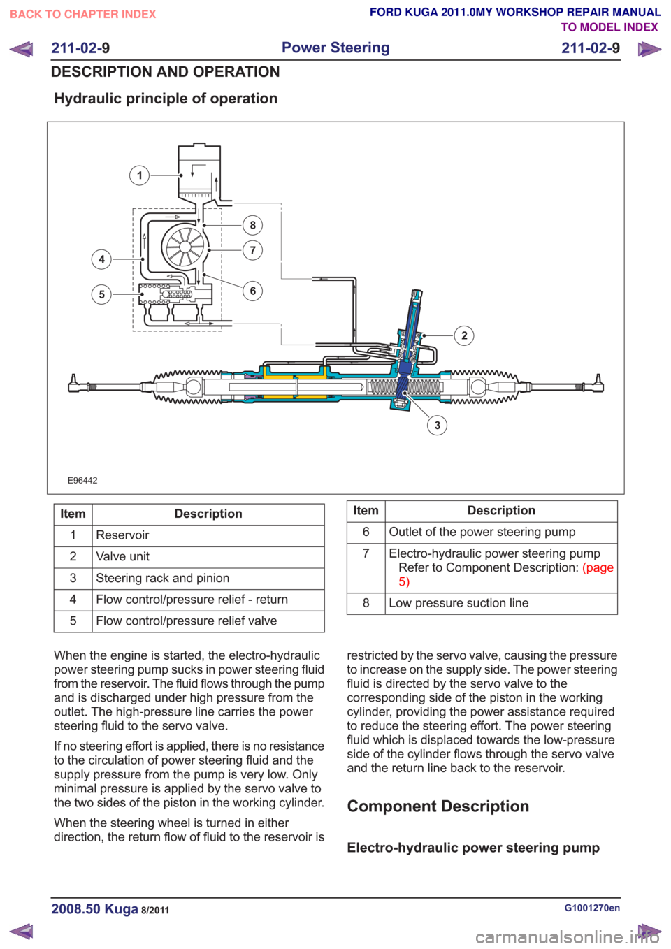
Hydraulic principle of operation
E96442
3
4
5
7
8
6
1
2
Description
Item
Reservoir
1
Valve unit
2
Steering rack and pinion
3
Flow control/pressure relief - return
4
Flow control/pressure relief valve
5Description
Item
Outlet of the power steering pump
6
Electro-hydraulic power steering pumpRefertoComponentDescription:(page
5)
7
Low pressure suction line
8
When the engine is started, the electro-hydraulic
power steering pump sucks in power steering fluid
from the reservoir. The fluid flows through the pump
and is discharged under high pressure from the
outlet. The high-pressure line carries the power
steering fluid to the servo valve.
If no steering effort is applied, there is no resistance
to the circulation of power steering fluid and the
supply pressure from the pump is very low. Only
minimal pressure is applied by the servo valve to
the two sides of the piston in the working cylinder.
When the steering wheel is turned in either
direction, the return flow of fluid to the reservoir is restricted by the servo valve, causing the pressure
to increase on the supply side. The power steering
fluid is directed by the servo valve to the
corresponding side of the piston in the working
cylinder, providing the power assistance required
to reduce the steering effort. The power steering
fluid which is displaced towards the low-pressure
side of the cylinder flows through the servo valve
and the return line back to the reservoir.
Component Description
Electro-hydraulic power steering pump
G1001270en2008.50 Kuga8/2011
211-02-
9
Power Steering
211-02- 9
DESCRIPTION AND OPERATION
TO MODEL INDEX
BACK TO CHAPTER INDEX
FORD KUGA 2011.0MY WORKSHOP REPAIR MANUAL
Page 1527 of 2057
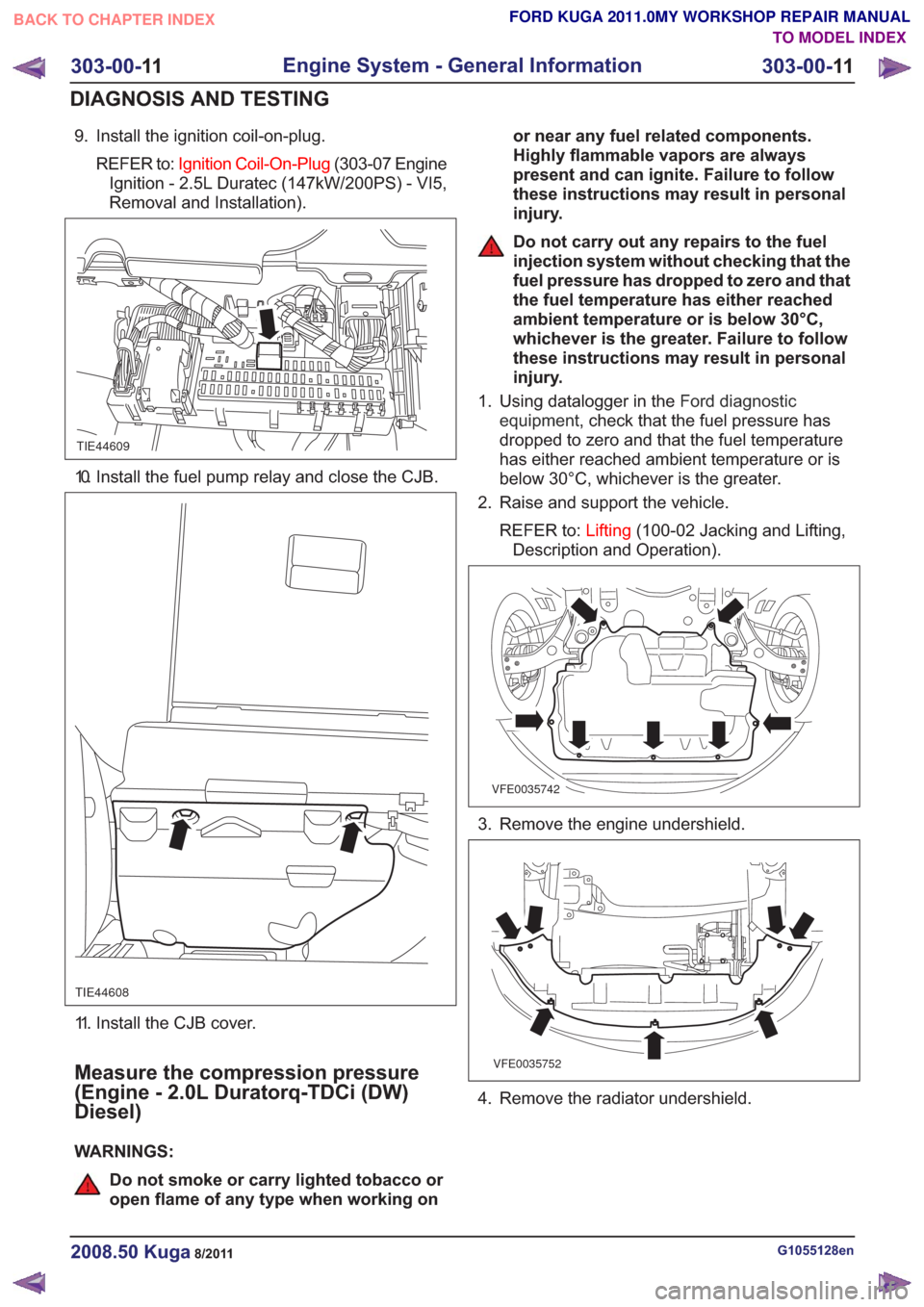
9. Install the ignition coil-on-plug.REFER to: Ignition Coil-On-Plug (303-07 Engine
Ignition - 2.5L Duratec (147kW/200PS) - VI5,
Removal and Installation).
TIE44609
10. Install the fuel pump relay and close the CJB.
TIE44608
11. Install the CJB cover.
Measure the compression pressure
(Engine - 2.0L Duratorq-TDCi (DW)
Diesel)
WARNINGS:
Do not smoke or carry lighted tobacco or
open flame of any type when working on or near any fuel related components.
Highly flammable vapors are always
present and can ignite. Failure to follow
these instructions may result in personal
injury.
Do not carry out any repairs to the fuel
injection system without checking that the
fuel pressure has dropped to zero and that
the fuel temperature has either reached
ambient temperature or is below 30°C,
whichever is the greater. Failure to follow
these instructions may result in personal
injury.
1. Using datalogger in the Ford diagnostic
equipment , check that the fuel pressure has
dropped to zero and that the fuel temperature
has either reached ambient temperature or is
below 30°C, whichever is the greater.
2. Raise and support the vehicle.
REFER to: Lifting(100-02 Jacking and Lifting,
Description and Operation).
VFE0035742
3. Remove the engine undershield.
VFE0035752
4. Remove the radiator undershield.
G1055128en2008.50 Kuga8/2011
303-00- 11
Engine System - General Information
303-00- 11
DIAGNOSIS AND TESTING
TO MODEL INDEX
BACK TO CHAPTER INDEX
FORD KUGA 2011.0MY WORKSHOP REPAIR MANUAL
Page 1795 of 2057
actuated) or opened (actuated). Each cylinder has
its own injector. The injection is accurately dosed
and takes place at a time determined by the PCM.
Injection takes place immediately in front of the
intake valves of the cylinder. The injectors are
actuated ground side via end-stages integrated
into the PCM and using the signal calculated by
the engine management system. Power is supplied
via the Powertrain Control Module relay in the BJB.
The injected fuel quantity depends on the opening
time, the fuel pressure and the diameter of the
nozzle holes.
The fuel metering is determined via open or
closed-loop control.
The open control loop differs from the closed
control loop in that the lambda control is
deactivated.
The PCM switches from closed to open-loop control
if the HO2S cools down to below 600°C or fails, as
well as when accelerating, coasting and at full load.
Regulation of injected fuel quantity via the PCM
involves:
• controlling the fuel pump,
• calculating the required quantity of fuel forengine starting,
• observance of the desired air/fuel ratio,
• calculating air mass,
• and calculating the fuel quantity for the different operating states and corresponding fuel
adjustment measures.
Open loop control
Open loop control is used primarily for fuel
injection, as long as the signals of the HO2S are
not involved in the calculation of the PCM.
The two most important reasons that make it
absolutely essential to run the engine without
lambda control (open-loop control) are the following
operating conditions:
• Cold engine (starting, warm-up phase)
• Full-load operation (WOT (wide open throttle))
Under these operating conditions the engine needs
a rich air/fuel mixture with lambda values below λ
= 1 in order to achieve optimum running or
optimum performance.
It is possible to keep this unregulated range very
small by using a broadband HO2S.
Closed-loop control
Closed loop control ensures strict control of
exhaust emissions in conjunction with the TWC (three-way catalytic converter) and economical fuel
consumption. With closed loop control, the signals
from the HO2S are analyzed by the PCM and the
engine always runs in the optimum range of λ = 1.
In addition to the normal HO2S, the signal from the
monitoring sensor for the catalytic converter is also
included in the control. The lambda control is
optimized on the basis of this data.
Certain factors such as wear, component
tolerances or more minor defects such as air leaks
in the intake system are compensated for by
lambda control. If the deviation occurs for a longer
period of time, this is recorded by the adaptive
(self-learning) function of lambda control. In this
instance, the entire map is shifted by the
corresponding amount, to enable control to
commence once again from the virtual baseline.
These adaptive settings are stored in the PCM and
are also used in open-loop control conditions.
If the adaptive value is too high or too low, an error
is stored in the fault memory of the PCM.
Oxygen sensor (HO2S) and catalyst monitor
sensor
A broadband HO2S is used as the HO2S. The
HO2S is located in front of the TWC. The catalyst
monitor sensor is located in the center of the TWC
so that it can detect any deterioration in the
cleaning performance of the TWC more quickly.
The HO2S measures the residual amount of
oxygen in the exhaust before the TWC.
The catalyst monitor sensor measures the amount
of oxygen in the exhaust gas after or in the TWC.
Both the HO2S and the catalyst monitor sensor
transmit these data to the PCM.
The broadband HO2S works at temperatures of
between 650°C and 900 °C. If the temperature
rises above 1000°C, the oxygen sensor will be
irreparably damaged.
To reach optimum operating temperature as quickly
as possible, an electrically-heated oxygen sensor
is installed. The heating also serves to maintain a
suitable operating temperature while coasting, for
example, when no hot gases are flowing past the
oxygen sensor.
The heating element in the HO2S is a PTC
(positive temperature coefficient) resistor. The
heating element is supplied with battery voltage as
soon as the Powertrain Control Module relay
engages. The HO2S is earthed via the PCM. As
the heating current is high when the element is
cold, it is limited via PWM in the PCM until a certain
G1021908en2008.50 Kuga8/2011
303-14-
21
Electronic Engine Controls— 2.5L Duratec (147kW/200PS) - VI5303-14-
21
DESCRIPTION AND OPERATION
TO MODEL INDEX
BACK TO CHAPTER INDEX
FORD KUGA 2011.0MY WORKSHOP REPAIR MANUAL
Page 2019 of 2057
Perform the leak test, by closing the hand valves
on the gauge set, switching off the service unit
vacuum pump and observing the low pressure
gauge.
10. N O T E : This step is only necessary if the
pressure increase exceeds 20 mbar.
Locate and rectify any leaks in the A/C
refrigerant circuit using a leak tester.
General Equipment: UV Leak Detector
General Equipment: Electronic Leak Detector
General Equipment: Automatic Calibration Halogen Leak Detector
11 . Add refrigerant oil to the air conditioning system.
Refer to: Specifications (412-00 Climate Control
System - General Information, Specifications).
Refer to: Refrigerant Oil Adding (412-00 Climate
Control System - General Information, General
Procedures).
12. Fill the air conditioning system with liquid
through the high-pressure connection.
Refer to: Specifications (412-00 Climate Control
System - General Information, Specifications).
13. Open the shut-off valve on the high-pressure
side.
1.
2. Switch the service unit to "Fill" mode and fill
the system with the specified quantity of
liquid refrigerant (R134a).
14. Fill the air conditioning system with gas through
the low-pressure connection.
Refer to: Specifications (412-00 Climate Control
System - General Information, Specifications).
15. Open the shut-off valve on the low-pressure
side.
1.
2. Switch the service unit to "Fill" mode and fill
the system with the specified quantity of
gaseous refrigerant.
3. Add the remaining amount of refrigerant with the air conditioning switched on. To do so
run the engine at about 1200-1500 rev/min.
Set the air conditioning system to full cooling
power and fresh air mode. Set the blower
motor to the highest setting. Fill with the
remainder of the specified fill capacity.
16. Disconnect the service unit. 17.
Close the shut-off valve.
1.
2. Switch off the service unit.
3. Disconnect the service unit lines from the
filling connections of the air conditioning
system.
4. Screw the protective caps onto the charging connections.
18. Install all components in reverse order.
G1022208en2008.50 Kuga8/2011
412-00- 8
Climate Control System - General Information
412-00- 8
GENERAL PROCEDURES
TO MODEL INDEX
BACK TO CHAPTER INDEX
FORD KUGA 2011.0MY WORKSHOP REPAIR MANUAL