2011 FORD KUGA ELECTRICAL
[x] Cancel search: ELECTRICALPage 8 of 2057

About This Manual
Introduction
This manual covers diagnosis and testing and
repair procedures.
It is structured into groups and sections, with
specific system sections grouped together under
their relevant group.
A group covers a specific portion of the vehicle.
The manual is divided into five groups, General
Information, Chassis, Powertrain, Electrical and
Body and Paint. The number of the group is the
first number of a section number.
Within Etis, the navigation tree will list the groups.
After selecting a group the navigation tree will then
list the sections within that group. Each section has
a contents list detailing Specifications, Description
and Operation, Diagnosis and Testing, General
Procedures, Disassembly and Assembly, Removal
and Installation.
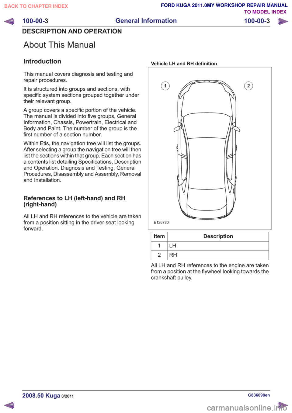
References to LH (left-hand) and RH
(right-hand)
All LH and RH references to the vehicle are taken
from a position sitting in the driver seat looking
forward.
Vehicle LH and RH definition
E126780
12
Description
Item
LH
1
RH
2
All LH and RH references to the engine are taken
from a position at the flywheel looking towards the
crankshaft pulley.
G836098en2008.50 Kuga8/2011
100-00- 3
General Information
100-00- 3
DESCRIPTION AND OPERATION
TO MODEL INDEX
BACK TO CHAPTER INDEX
FORD KUGA 2011.0MY WORKSHOP REPAIR MANUAL
Page 9 of 2057

Powertrain LH and RH definition
E126781
1
2
3
4
Description
Item
front
1
right hand
2
rear
3
left hand
4
How to use Repair Procedures
This manual has been written in a format that is
designed to meet the needs of technicians
worldwide. It provides general descriptions for
accomplishing repair work with tested and effective
techniques.
Important Safety Instructions
Appropriate service methods and correct repair
procedures are essential for the safe and reliable
operation of all vehicles as well as the personal
safety of the individual carrying out the work.
Anyone who departs from the instructions provided
in this manual must first establish that personal safety or vehicle integrity is not compromised by
the choice of method, tools or components.
Warnings, Cautions and Notes in This
Manual
WARNING: Warnings are used to indicate
that failure to follow a procedure correctly
may result in personal injury.
CAUTION: Cautions are used to indicate
that failure to follow a procedure correctly
may result in damage to the vehicle or
equipment being used.
NOTE: Notes are used to provide additional
essential information required to carry out a
complete and satisfactory repair.
Generic warnings or cautions are in their relevant
description and operation procedure within section
100-00. If the generic warnings or cautions are
required for a procedure, there will be a referral to
the appropriate description and operation
procedure.
If a warning, caution or note only applies to one
step, it is placed at the beginning of the specific
step.
Global Authoring Standards (GAS) Repair
Procedures
NOTE: GAS style procedures can be identified by
steps that have no accompanying step text and
the magenta color of the electrical connectors and
fasteners such as nuts, bolts, clamps or clips.
A GAS removal and installation procedure uses a
sequence of color illustrations to indicate the order
to be followed when removing/disassembling or
installing/assembling a component.
Many of the GAS procedures will have the
installation information within the removal steps.
These procedures will have the following note at
the beginning of the procedure:
NOTE: Removal steps in this procedure may
contain installation details.
Reuse of fasteners and seals and gaskets
The following list details the general policy for the
reuse of fasteners and seals and gaskets.
G836098en2008.50 Kuga8/2011
100-00- 4
General Information
100-00- 4
DESCRIPTION AND OPERATION
TO MODEL INDEX
BACK TO CHAPTER INDEX
FORD KUGA 2011.0MY WORKSHOP REPAIR MANUAL
Page 11 of 2057

numerically in a graphic and the corresponding text
will be numbered accordingly.
Special Tools, Equipment, Materials and Torque
Figures
Special tools will be shown with the tool numbers
in the illustration. The special tool numbers, general
equipment, materials and torque figures used for
the procedure step will be shown in the text
column.
GAS Graphics
NOTE:Colors used in the graphic are as follows:
4
6
5
14
2
36
5
E141161
Description
Item
Blue - Target or primary component to be
removed/installed (or
disassembled/assembled).
1
Green - Components that need to be
removed prior to or installed after the
target/primary.
2
Description
Item
Brown - Components that need to be
removed prior to or installed after the
target/primary.
3
Yellow - Components to be set aside only,
that remains in the vehicle. Also
highlighted areas to inspect or adjust.
4
Magenta - Electrical connectors and
fasteners such as nuts, bolts, clamps, or
5
clips to be: detached, attached, loosened,
moved, removed or installed.
Pale Blue - Special tool(s), general
equipment, or common tools (used in an
uncommon way).
6
One illustration may have multiple steps assigned
to it.
Numbered pointers are used to indicate the number
of electrical connectors and fasteners such as nuts,
bolts, clamps and clips.
Items in the illustration can be transparent or use
cutouts to show hidden details.
E132042
x2
1
2
3
G836098en2008.50 Kuga8/2011
100-00- 6
General Information
100-00- 6
DESCRIPTION AND OPERATION
TO MODEL INDEX
BACK TO CHAPTER INDEX
FORD KUGA 2011.0MY WORKSHOP REPAIR MANUAL
Page 24 of 2057

How to use Diagnosis and Testing
procedures
Inspection and Verification
Visual Inspection Charts, Symptom Charts and
other information charts (such as diagnostic
routines) or supplement test procedures with
technical specifications will navigate the user to a
specific test procedure.
Symptom Chart
The symptom chart indicates symptoms, sources
and actions to address a condition.
Pinpoint Tests
For electrical systems, pinpoint test steps are used
to identify the source of a concern in a logical,
step-by-step manner. Pinpoint tests have two
columns: CONDITIONS and
DETAILS/RESULTS/ACTIONS.
The CONDITIONS column is used exclusively for
graphics and icons (with or without captions) and
the DETAILS/RESULTS/ACTIONS column
provides direction to another test step or specific
corrective actions.
The boxed numbers indicate the order in which the
described action is to be carried out.
Component Tests
A component test is used when a component is
tested in multiple pinpoint tests, or if a procedure
is too complicated to be formatted within a single
page of the pinpoint test.
Graphics
Test graphics show the measurement or test to be
carried out in a test step.
A representative tester graphic is used for
voltmeters and ohmmeters.
If multiple measurements are made in a single
graphic, the test leads are drawn with a solid line
until the test lead splits to indicate the multiple
measurements, at which point dashed lines are
used.
Breakout box type testers are represented by a
double circle test pin. Test pins are labeled with
the pin number.
G836098en2008.50 Kuga8/2011
100-00-18
General Information
100-00- 18
DESCRIPTION AND OPERATION
TO MODEL INDEX
BACK TO CHAPTER INDEX
FORD KUGA 2011.0MY WORKSHOP REPAIR MANUAL
Page 44 of 2057

E89021
123
56
798
12
4
13
Description
Item
Hazardous voltage/Electrical
shock/Electrocution
1
Fire Hazard/Highly flammable
2
Burn hazard/Hot surface
3
Automatic start-up
4
Toxic
5
Explosive material
6
Battery hazard
7Description
Item
Corrosive material
8
Lifting hazard
9
Hand crush/Force from above
10
Cutting of fingers or hand
11
Pressure hazard
12
Invisible laser radiation. Do not view
directly with optical instruments
(magnifiers). Class 1M laser product
13
G955392en2008.50 Kuga8/2011
100-00-
39
General Information
100-00- 39
DESCRIPTION AND OPERATION
TO MODEL INDEX
BACK TO CHAPTER INDEX
FORD KUGA 2011.0MY WORKSHOP REPAIR MANUAL
Page 47 of 2057

Exhaust Fumes
These contain asphyxiating, harmful and toxic
chemicals and particles such as carbon oxides,
nitrogen oxides, aldehydes, lead and aromatic
hydrocarbons. Engines should be run only under
conditions of adequate exhaust extraction or
general ventilation and not in confined spaces.
Gasoline (petrol) engine
There may not be adequate warning of odor or of
irritation before toxic or harmful effects arise. These
may be immediate or delayed.
Diesel engine
Soot, discomfort and irritation usually give
adequate warning of hazardous fume
concentrations.
Fibre Insulation
See alsoDusts.
Used in noise and sound insulation.
The fibrous nature of surfaces and cut edges can
cause skin irritation. This is usually a physical and
not a chemical effect.
Precautions should be taken to avoid excessive
skin contact through careful organization of work
practices and the use of gloves.
Fire
See also Welding,Foams,Legal Aspects.
Many of the materials found on or associated with
the repair of vehicles are highly flammable. Some
give off toxic or harmful fumes if burnt.
Observe strict fire safety when storing and handling
flammable materials or solvents, particularly near
electrical equipment or welding processes.
Make sure, before using electrical or welding
equipment, that there is no fire hazard present.
Have a suitable fire extinguisher available when
using welding or heating equipment.
First Aid
Apart from meeting any legal requirements it is
desirable for someone in the workshop to be
trained in First Aid procedures.
Splashes in the eye should be flushed carefully
with clean water for at least ten minutes.
Soiled skin should be washed with soap and water.
In case of cold burns, from alternative fuels, place
affected area in cool to cold water.
Individuals affected by inhalation of gases and
fumes should be removed to fresh air immediately.
If effects persist, consult a doctor.
If liquids are swallowed inadvertently, consult a
doctor giving him the information on the container
or label. Do not induce vomiting unless this action
is indicated on the label.
Fluoroelastomer
See Viton.
Foams - Polyurethane
See also Fire.
Used in sound and noise insulation. Cured foams
used in seat and trim cushioning.
Follow manufacturers instructions.
Unreacted components are irritating and may be
harmful to the skin and eyes. Wear gloves and
goggles.
Individuals with chronic respiratory diseases,
asthma, bronchial medical problems, or histories
of allergic diseases should not work in or near
uncured materials.
The components, vapors or spray mists can cause
direct irritation, sensitivity reactions and may be
toxic or harmful.
Vapors and spray mists must not be inhaled. These
materials must be applied with adequate ventilation
and respiratory protection. Do not remove the
respirator immediately after spraying; wait until the
vapors/mists have cleared.
Burning of the uncured components and the cured
foams can generate toxic and harmful fumes.
Smoking, naked flames or the use of electrical
equipment during foaming operations and until
vapors/mists have cleared should not be allowed.
Any heat cutting of cured foams or partially cured
G566527en2008.50 Kuga8/2011
100-00- 46
General Information
100-00- 46
DESCRIPTION AND OPERATION
TO MODEL INDEX
BACK TO CHAPTER INDEX
FORD KUGA 2011.0MY WORKSHOP REPAIR MANUAL
Page 52 of 2057

dermatitis or be absorbed through the skin in
toxic or harmful quantities.
– Do not use emptied containers for other materials except when they have been cleaned
under supervised conditions.
– Do not sniff or smell chemical materials. Brief exposure to high concentrations of fumes can
be toxic or harmful.
Chlorofluorocarbons (CFC)
There is concern in the scientific community that
CFCs and Halons are depleting the upper ozone
layer which filters out harmful ultraviolet radiation.
Decreased filtration of ultraviolet radiation may
result in increases in skin cancer, cataracts and
immune system suppression in humans, as well
as decreased productivity of crops and aquatic
systems.
CFCs are used primarily as refrigerants in vehicle
air conditioning systems and as aerosol
propellants. Halons are used as fire extinguishants.
Clutch Fluids
See Brake fluids.
Clutch Linings and Pads
SeeAsbestos.
Corrosion Protection Materials
See also Solvents, Fire.
Highly flammable, flammable – observe No
Smoking policy.
These materials are varied and the manufacturers
instructions must be followed. They may contain
solvents, resins or petroleum products. Skin and
eye contact should be avoided. They should only
be sprayed in conditions of adequate ventilation
and not in confined spaces.
Cutting
See Welding.
Dewaxing
SeeSolvents andFuels (Kerosene).
Dusts
Powder, dusts or clouds may be irritant, harmful
or toxic. Avoid breathing dusts from powdery
chemical materials or those arising from dry
abrasion operations. Wear respiratory protection
if ventilation is inadequate.
Fine dusts of combustible material can present an
explosion hazard. Avoid explosive limits and
sources of ignition.
Electric Shock
Electric shock can result from the use of faulty
electrical equipment or from the misuse of
equipment in good condition.
Make sure that electrical equipment is maintained
in good condition and frequently tested. Faulty
equipment should be labeled and preferably
removed from the workstation.
Make sure that flexes, cables, plugs and sockets
are not frayed, kinked, cut, cracked or otherwise
damaged.
Make sure that electrical equipment and flexes do
not come into contact with water.
Make sure that electrical equipment is protected
by the correct rated fuse.
Never misuse electrical equipment and never use
equipment that is in any way faulty. The results
could be fatal.
Make sure that the cables of mobile electrical
equipment cannot get trapped and damaged, such
as in a vehicle hoist.
Make sure that the designated electrical workers
are trained in basic First Aid.
In cases of electrocution:
– switch off the power supply before approaching
the victim.
– if this is not possible push or drag the victim from the source of electricity using dry
non-conductive material.
– commence resuscitation if trained to do so.
– SUMMON MEDICAL ASSISTANCE.
Engine Oils
See Lubricants and Grease.
G566527en2008.50 Kuga8/2011
100-00- 45
General Information
100-00- 45
DESCRIPTION AND OPERATION
TO MODEL INDEX
BACK TO CHAPTER INDEX
FORD KUGA 2011.0MY WORKSHOP REPAIR MANUAL
Page 60 of 2057

Standard Workshop Practices
Vehicle in Workshop
When working on a vehicle in the workshop always
make sure that:
– the parking brake is applied or the wheels aresecurely chocked to prevent the vehicle moving
forwards or backwards.
– the key is removed from key operated hood locks before any work is carried out around the
front of the vehicle.
– if the engine is to be run, there is adequate ventilation, or an extraction hose to remove
exhaust fumes.
– there is adequate room to raise the vehicle and remove the wheels, if necessary.
– fender covers are always fitted if any work is to be carried out in the engine compartment.
– the battery is disconnected if working on the engine, underneath the vehicle, or if the vehicle
is raised.
CAUTION: When electric arc welding on a
vehicle, always disconnect the generator
wiring to prevent the possibility of a surge
of current causing damage to the internal
components of the generator.
– if using welding equipment on the vehicle, a suitable fire extinguisher is readily available.
Towing the Vehicle
WARNING: When the vehicle is being
towed, the ignition switch must be in
position II (steering lock released and
warning lamps illuminated). Only then will
the steering, turn signal lamps, horn and
stop lamps be operational. Failure to follow
these instructions may result in personal
injury.
NOTE: The removable towing eye (if equipped),
has a left-hand thread and must be fully tightened
before towing can commence.
When towing is necessary, the vehicle towing eyes
should be used. The rope must be securely
fastened to the towing eyes and must also be
attached to the other vehicle such that the rope will
not foul the bodywork.
When a vehicle with automatic transmission is
towed, the gear selector must be in position N (Neutral). Never tow a vehicle with automatic
transmission at a speed greater than 30 mph (50
km/h) or for a distance greater than 30 miles (50
km). If it is necessary to tow the vehicle a greater
distance, the drive wheels must be lifted clear off
the ground.
Alternatively the vehicle can be transported on a
low loader or a trailer.
Connecting a Slave Battery Using
Jumper Cables
WARNING: If the slave battery has recently
been charged and is gassing, cover the
vent plugs or covers with a damp cloth to
reduce the risk of explosion should arcing
occur when connecting the jumper cables.
Failure to follow these instructions may
result in personal injury.
CAUTIONS:
A discharged battery condition may have
been caused by an electrical short circuit.
If this condition exists there will be an
apparently live circuit on the vehicle even
when all normal circuits are switched off.
This can cause arcing when the jumper
cables are connected.
While it is not recommended that the
vehicle is jump started, it is recognized
that this may occasionally be the only
practical way to mobilize a vehicle. In such
an instance, the discharged battery must
be recharged immediately after jump
starting to avoid permanent damage.
– Always make sure that the jumper cables are adequate for the task. Heavy duty cables must
be used.
– Always make sure that the slave battery is of the same voltage as the vehicle battery. The
batteries must be connected in parallel.
– Always make sure that switched electric circuits are switched off before connecting jumper
cables. This reduces the risk of arcing occurring
when the final connection is made.
G17373en2008.50 Kuga8/2011
100-00- 54
General Information
100-00- 54
DESCRIPTION AND OPERATION
TO MODEL INDEX
BACK TO CHAPTER INDEX
FORD KUGA 2011.0MY WORKSHOP REPAIR MANUAL