2011 FORD KUGA Fuel tank pump
[x] Cancel search: Fuel tank pumpPage 166 of 2057
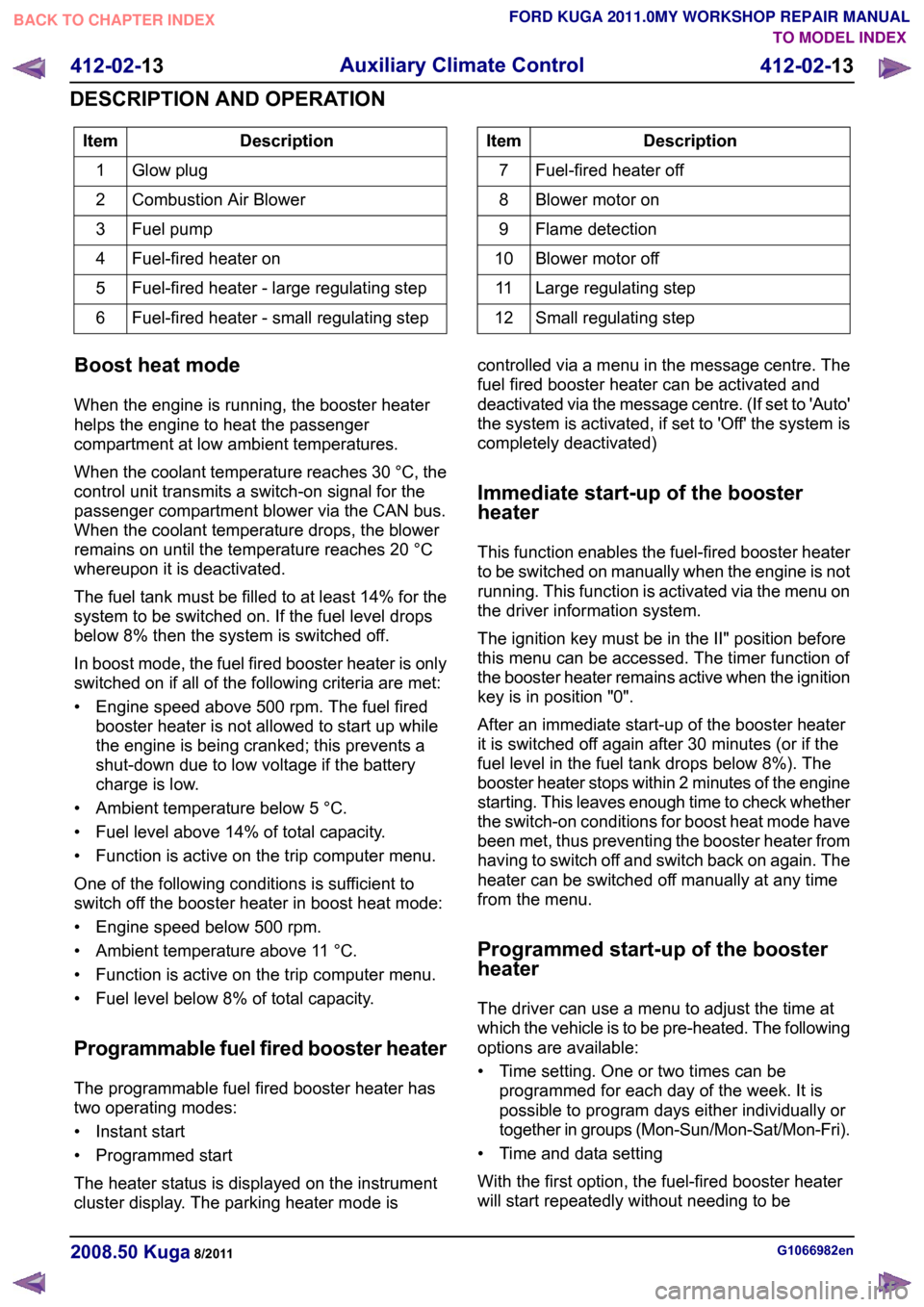
Description
Item
Glow plug
1
Combustion Air Blower
2
Fuel pump
3
Fuel-fired heater on
4
Fuel-fired heater - large regulating step
5
Fuel-fired heater - small regulating step
6 Description
Item
Fuel-fired heater off
7
Blower motor on
8
Flame detection
9
Blower motor off
10
Large regulating step
11
Small regulating step
12
Boost heat mode
When the engine is running, the booster heater
helps the engine to heat the passenger
compartment at low ambient temperatures.
When the coolant temperature reaches 30 °C, the
control unit transmits a switch-on signal for the
passenger compartment blower via the CAN bus.
When the coolant temperature drops, the blower
remains on until the temperature reaches 20 °C
whereupon it is deactivated.
The fuel tank must be filled to at least 14% for the
system to be switched on. If the fuel level drops
below 8% then the system is switched off.
In boost mode, the fuel fired booster heater is only
switched on if all of the following criteria are met:
• Engine speed above 500 rpm. The fuel fired booster heater is not allowed to start up while
the engine is being cranked; this prevents a
shut-down due to low voltage if the battery
charge is low.
• Ambient temperature below 5 °C.
• Fuel level above 14% of total capacity.
• Function is active on the trip computer menu.
One of the following conditions is sufficient to
switch off the booster heater in boost heat mode:
• Engine speed below 500 rpm.
• Ambient temperature above 11 °C.
• Function is active on the trip computer menu.
• Fuel level below 8% of total capacity.
Programmable fuel fired booster heater
The programmable fuel fired booster heater has
two operating modes:
• Instant start
• Programmed start
The heater status is displayed on the instrument
cluster display. The parking heater mode is controlled via a menu in the message centre. The
fuel fired booster heater can be activated and
deactivated via the message centre. (If set to 'Auto'
the system is activated, if set to 'Off' the system is
completely deactivated)
Immediate start-up of the booster
heater
This function enables the fuel-fired booster heater
to be switched on manually when the engine is not
running. This function is activated via the menu on
the driver information system.
The ignition key must be in the II" position before
this menu can be accessed. The timer function of
the booster heater remains active when the ignition
key is in position "0".
After an immediate start-up of the booster heater
it is switched off again after 30 minutes (or if the
fuel level in the fuel tank drops below 8%). The
booster heater stops within 2 minutes of the engine
starting. This leaves enough time to check whether
the switch-on conditions for boost heat mode have
been met, thus preventing the booster heater from
having to switch off and switch back on again. The
heater can be switched off manually at any time
from the menu.
Programmed start-up of the booster
heater
The driver can use a menu to adjust the time at
which the vehicle is to be pre-heated. The following
options are available:
• Time setting. One or two times can be
programmed for each day of the week. It is
possible to program days either individually or
together in groups (Mon-Sun/Mon-Sat/Mon-Fri).
• Time and data setting
With the first option, the fuel-fired booster heater
will start repeatedly without needing to be G1066982en
2008.50 Kuga 8/2011 412-02-13
Auxiliary Climate Control
412-02-13
DESCRIPTION AND OPERATIONTO MODEL INDEX
BACK TO CHAPTER INDEX
FORD KUGA 2011.0MY WORKSHOP REPAIR MANUAL
Page 169 of 2057
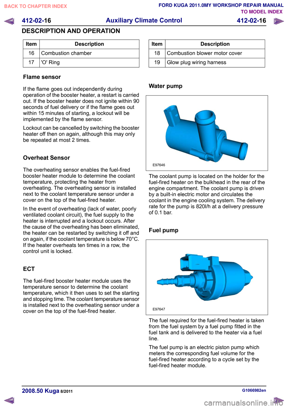
Description
Item
Combustion chamber
16
'O' Ring
17 Description
Item
Combustion blower motor cover
18
Glow plug wiring harness
19
Flame sensor
If the flame goes out independently during
operation of the booster heater, a restart is carried
out. If the booster heater does not ignite within 90
seconds of fuel delivery or if the flame goes out
within 15 minutes of starting, a lockout will be
implemented by the flame sensor.
Lockout can be cancelled by switching the booster
heater off then on again, although this may only
be repeated at most 2 times.
Overheat Sensor
The overheating sensor enables the fuel-fired
booster heater module to determine the coolant
temperature, protecting the heater from
overheating. The overheating sensor is installed
next to the coolant temperature sensor under a
cover on the top of the fuel-fired heater.
In the event of overheating (lack of water, poorly
ventilated coolant circuit), the fuel supply to the
heater is interrupted and a lockout occurs. After
the cause of the overheating has been eliminated,
the heater can be restarted by switching it off and
on again, if the coolant temperature is below 70°C.
If the heater overheats ten times in a row, the
control unit is locked.
ECT
The fuel-fired booster heater module uses the
temperature sensor to determine the coolant
temperature, which it then uses to set the starting
and stopping time. The coolant temperature sensor
is installed next to the overheating sensor under a
cover on the top of the fuel-fired heater. Water pump The coolant pump is located on the holder for the
fuel-fired heater on the bulkhead in the rear of the
engine compartment. The coolant pump is driven
by a built-in electric motor and circulates the
coolant in the engine cooling system. The delivery
rate for the pump is 820l/h at a delivery pressure
of 0.1 bar.
Fuel pump
The fuel required for the fuel-fired heater is taken
from the fuel system by a fuel pump fitted in the
fuel tank and is delivered to the heater via a fuel
line.
The fuel pump is an electric piston pump which
meters the corresponding fuel volume for the
fuel-fired heater according to a cycle set by the
fuel-fired heater module.
G1066982en
2008.50 Kuga 8/2011 412-02-16
Auxiliary Climate Control
412-02-16
DESCRIPTION AND OPERATIONTO MODEL INDEX
BACK TO CHAPTER INDEX
FORD KUGA 2011.0MY WORKSHOP REPAIR MANUALE97646 E97647
Page 178 of 2057

Fuel Fired Booster Heater Fuel Pump
Removal
1.
Refer to: Petrol and Petrol-Ethanol Fuel
Systems Health and Safety Precautions
(100-00 General Information, Description and
Operation).
2. Refer to: Fuel Tank - 2.5L Duratec
(147kW/200PS) - VI5 (310-01 Fuel Tank and
Lines, Removal and Installation).
3. Refer to: Quick Release Coupling (310-00 Fuel
System - General Information, General
Procedures). Installation
1.
To install, reverse the removal procedure. G1163564en
2008.50 Kuga 8/2011 412-02-25
Auxiliary Climate Control
412-02-25
REMOVAL AND INSTALLATIONTO MODEL INDEX
BACK TO CHAPTER INDEX
FORD KUGA 2011.0MY WORKSHOP REPAIR MANUALE112750
Page 187 of 2057

Description
Item
Instrument Cluster
1
PCM (powertrain control module)
2
EHPS (electro-hydraulic power steering)
control module
3
Audio unit
4
GEM (generic electronic module)
5
RCM (restraints control module)
6
PATS transceiver
7 Description
Item
Steering wheel lock module
8
Left-hand steering column switch
9
Fuel level sensor
10
Washer water level warning lamp switch
11
Accelerator pedal position sensor
12
CPP (clutch pedal position) sensor/BPP
(brake pedal position) sensor
13
Lighting control switch
14
System Operation
Instrument Cluster
The instrument cluster contains analog displays
as well as warning and control lamps for displaying
the system status; in addiiton, there is an LCD
indicator field for driver information.
The instrument cluster receives the following
signals from the PCM via the high speed CAN
(controller area network) Bus (HS-CAN):
• Vehicle speed – The PCM receives the necessary signalsfrom the ABS (anti-lock brake system) wheel
sensors from the ABS control unit on the
HS-CAN.
• Engine Coolant Temperature
• Engine oil pressure.
• Engine speed
The instrument cluster receives the following
signals from the GEM via the medium speed CAN
Bus (MS-CAN):
• Ambient temperature
• Brake fluid level
• Handbrake control
• Door latch control
• Liftgate latch control
• High beam control
• Headlamp flasher control
• Direction indicator control
The fuel level signal is sent by the two fuel level
sensors in the fuel pumps in the semitrailer tank,
which is wired to the instrument cluster. The
sensors are connected in series, and the total
resistance is determined from the two individual resistors. The instrument cluster converts the raw
fuel level signal into a damped fuel level value.
The odometer shows the total distance travelled
by the vehicle and is based on the same signal as
is processed for the daily mileage counter. The
value is recorded by the instrument cluster and
stored in a protected EEPROM (Electronically
Erasable Programmable Read Only Memory) area.
This area is a memory protected against
manipulation. If the instrument cluster detects an
error in this memory area, e.g. through damage,
the driver is notified with the "Odometer error"
message.
Message center
The message center is operated using the left-hand
switch on the steering column.
The SET/RESET button is activated to select a
submenu and change the settings. If signal tones
have been activated, a short acoustic signal will
sound each time a button is pressed.
By turning the rotary switch, the different menu
displays can be scrolled through or a setting
selected.
In this display, the navigation system can also
display direction and distance information.
In addition, safety and warning messages can be
displayed in this system, such as "Coolant
overheating", "Engine system error" or "Washer
fluid level too low". In addition to a safety message,
a general warning light (red/yellow) lights up.
G1030770en
2008.50 Kuga 8/2011 413-01-4
Instrument Cluster
413-01-4
DESCRIPTION AND OPERATIONTO MODEL INDEX
BACK TO CHAPTER INDEX
FORD KUGA 2011.0MY WORKSHOP REPAIR MANUAL
Page 1696 of 2057
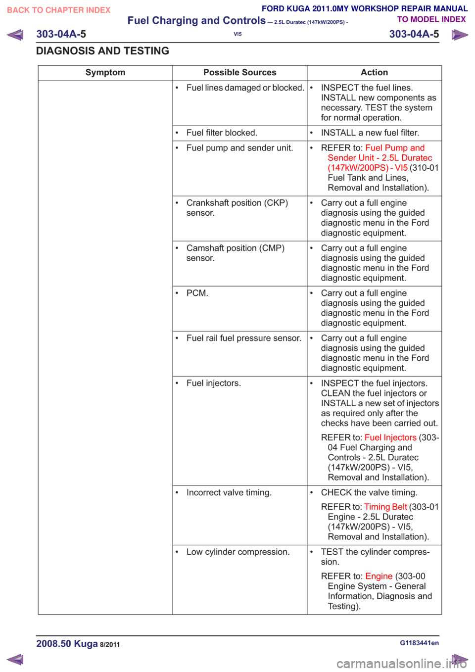
Action
Possible Sources
Symptom
• INSPECT the fuel lines.INSTALL new components as
necessary. TEST the system
for normal operation.
• Fuel lines damaged or blocked.
• INSTALL a new fuel filter.
• Fuel filter blocked.
• REFER to:Fuel Pump and
Sender Unit - 2.5L Duratec
(147kW/200PS) - VI5 (310-01
Fuel Tank and Lines,
Removal and Installation).
• Fuel pump and sender unit.
• Carry out a full enginediagnosis using the guided
diagnostic menu in the Ford
diagnostic equipment.
• Crankshaft position (CKP)
sensor.
• Carry out a full enginediagnosis using the guided
diagnostic menu in the Ford
diagnostic equipment.
• Camshaft position (CMP)
sensor.
• Carry out a full enginediagnosis using the guided
diagnostic menu in the Ford
diagnostic equipment.
•PCM.
• Carry out a full enginediagnosis using the guided
diagnostic menu in the Ford
diagnostic equipment.
• Fuel rail fuel pressure sensor.
• INSPECT the fuel injectors.CLEAN the fuel injectors or
INSTALL a new set of injectors
as required only after the
checks have been carried out.
REFER to: Fuel Injectors (303-
04 Fuel Charging and
Controls - 2.5L Duratec
(147kW/200PS) - VI5,
Removal and Installation).
• Fuel injectors.
• CHECK the valve timing.REFER to: Timing Belt (303-01
Engine - 2.5L Duratec
(147kW/200PS) - VI5,
Removal and Installation).
• Incorrect valve timing.
• TEST the cylinder compres-sion.
REFER to: Engine(303-00
Engine System - General
Information, Diagnosis and
Testing).
• Low cylinder compression.
G1183441en2008.50 Kuga8/2011
303-04A-
5
Fuel Charging and Controls
— 2.5L Duratec (147kW/200PS) -
VI5
303-04A- 5
DIAGNOSIS AND TESTING
TO MODEL INDEX
BACK TO CHAPTER INDEX
FORD KUGA 2011.0MY WORKSHOP REPAIR MANUAL
Page 1790 of 2057
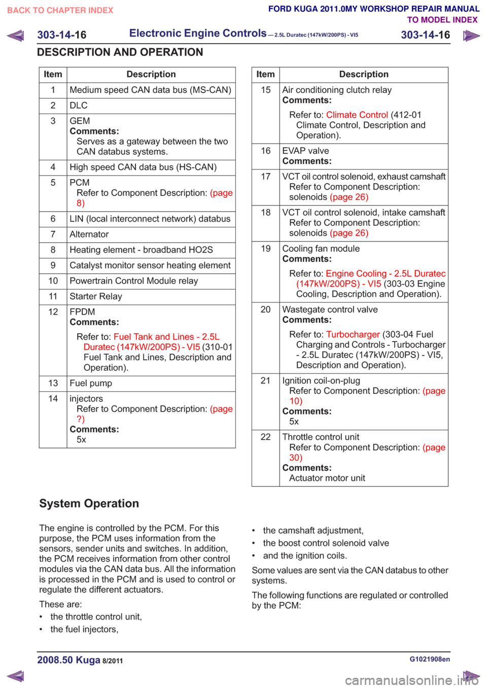
Description
Item
Medium speed CAN data bus (MS-CAN)
1
DLC
2
GEM
Comments:Serves as a gateway between the two
CAN databus systems.
3
High speed CAN data bus (HS-CAN)
4
PCMRefertoComponentDescription:(page
8)
5
LIN (local interconnect network) databus
6
Alternator
7
Heating element - broadband HO2S
8
Catalyst monitor sensor heating element
9
Powertrain Control Module relay
10
Starter Relay
11
FPDM
Comments:Refer to: Fuel Tank and Lines - 2.5L
Duratec (147kW/200PS) - VI5 (310-01
Fuel Tank and Lines, Description and
Operation).
12
Fuel pump
13
injectorsRefertoComponentDescription:(page
?)
Comments: 5x
14Description
Item
Air conditioning clutch relay
Comments:Refer to: Climate Control (412-01
Climate Control, Description and
Operation).
15
EVAP valve
Comments:
16
VCT oil control solenoid, exhaust camshaftRefer to Component Description:
solenoids(page26)
17
VCT oil control solenoid, intake camshaftRefer to Component Description:
solenoids(page26)
18
Cooling fan module
Comments:Refer to: Engine Cooling - 2.5L Duratec
(147kW/200PS) - VI5 (303-03 Engine
Cooling, Description and Operation).
19
Wastegate control valve
Comments:Refer to: Turbocharger (303-04 Fuel
Charging and Controls - Turbocharger
- 2.5L Duratec (147kW/200PS) - VI5,
Description and Operation).
20
Ignition coil-on-plugRefertoComponentDescription:(page
10)
Comments: 5x
21
Throttle control unitRefertoComponentDescription:(page
30)
Comments: Actuator motor unit
22
System Operation
The engine is controlled by the PCM. For this
purpose, the PCM uses information from the
sensors, sender units and switches. In addition,
the PCM receives information from other control
modules via the CAN data bus. All the information
is processed in the PCM and is used to control or
regulate the different actuators.
These are:
• the throttle control unit,
• the fuel injectors, • the camshaft adjustment,
• the boost control solenoid valve
• and the ignition coils.
Some values are sent via the CAN databus to other
systems.
The following functions are regulated or controlled
by the PCM:
G1021908en2008.50 Kuga8/2011
303-14-
16
Electronic Engine Controls— 2.5L Duratec (147kW/200PS) - VI5303-14-
16
DESCRIPTION AND OPERATION
TO MODEL INDEX
BACK TO CHAPTER INDEX
FORD KUGA 2011.0MY WORKSHOP REPAIR MANUAL
Page 1792 of 2057
• Torque reduction request (stability assistmodule)
• Cruise control request
The PCM sends the following signals via the CAN
databus:
• Fuel pump relay on/off
• Engine speed
• Warning lights on/off (MIL (malfunction indicator lamp), battery warning lamp)
• PAT S
•ECT
• Air conditioning pressure transducer
• Outside air temperature
With the aid of the input and output signals listed
above, the PCM controls / regulates engine
starting, fuel injection and fuel pressure, ignition,
boost pressure, camshaft adjustment, tank purging,
the radiator fan and the refrigerant compressor.
Speed and TDC recording
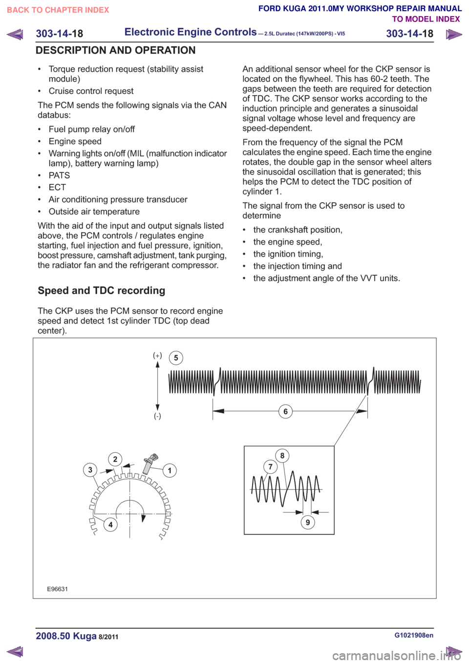
The CKP uses the PCM sensor to record engine
speed and detect 1st cylinder TDC (top dead
center). An additional sensor wheel for the CKP sensor is
located on the flywheel. This has 60-2 teeth. The
gaps between the teeth are required for detection
of TDC. The CKP sensor works according to the
induction principle and generates a sinusoidal
signal voltage whose level and frequency are
speed-dependent.
From the frequency of the signal the PCM
calculates the engine speed. Each time the engine
rotates, the double gap in the sensor wheel alters
the sinusoidal oscillation that is generated; this
helps the PCM to detect the TDC position of
cylinder 1.
The signal from the CKP sensor is used to
determine
• the crankshaft position,
• the engine speed,
• the ignition timing,
• the injection timing and
• the adjustment angle of the VVT units.
2
3
4
1
9
7
8
6
5
2
3
4
1
9
7
8
6
5
E96631
G1021908en2008.50 Kuga8/2011
303-14-
18
Electronic Engine Controls— 2.5L Duratec (147kW/200PS) - VI5303-14-
18
DESCRIPTION AND OPERATION
TO MODEL INDEX
BACK TO CHAPTER INDEX
FORD KUGA 2011.0MY WORKSHOP REPAIR MANUAL
Page 1979 of 2057
Fuel Tank Draining
General EquipmentFluid Container
Fuel Tank Draining Equipment
Hose Clamp Remover/Installer
Activation
CAUTION: If the fuel tank has been filled
with the wrong type of fuel, the engine
must not be started.
NOTE: Removal steps in this procedure may
contain installation details.
6. Refer to: Petrol and Petrol-Ethanol Fuel
Systems Health and Safety Precautions
(100-00 General Information, Description and
Operation).
7. Refer to: Lifting(100-02 Jacking and Lifting,
Description and Operation).
8. WARNINGS:
Fuel may still be present in the fuel tank
after draining.
Be prepared to collect escaping fluids.
CAUTION: Use suitable paper to absorb
any escaping fluid. NOTE:
Make sure that a new component is
installed.
• General Equipment: Hose Clamp Remover/Installer
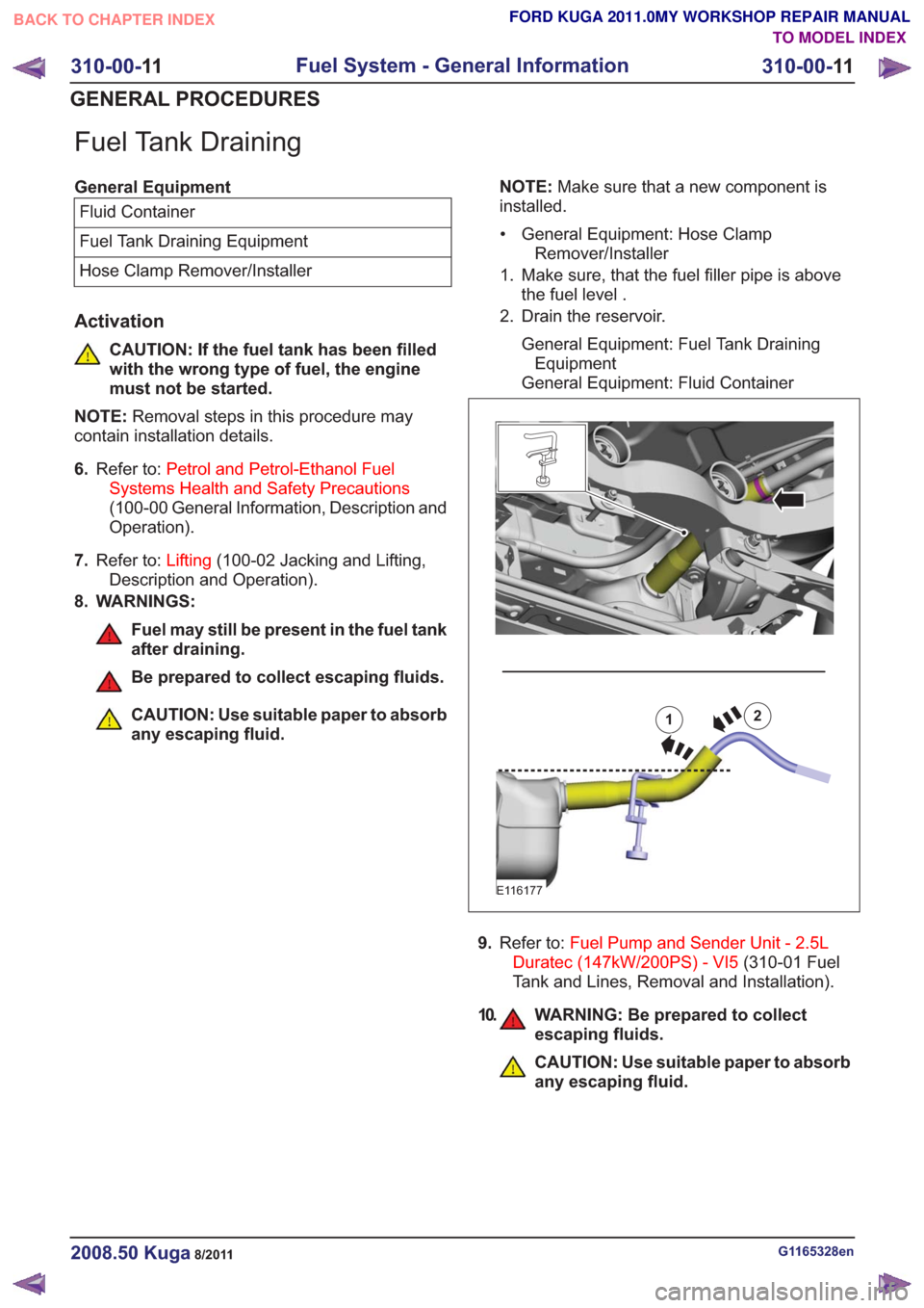
1. Make sure, that the fuel filler pipe is above the fuel level .
2. Drain the reservoir.
General Equipment: Fuel Tank DrainingEquipment
General Equipment: Fluid Container12
E116177
9. Refer to: Fuel Pump and Sender Unit - 2.5L
Duratec (147kW/200PS) - VI5 (310-01 Fuel
Tank and Lines, Removal and Installation).
10. WARNING: Be prepared to collect escaping fluids.
CAUTION: Use suitable paper to absorb
any escaping fluid.
G1165328en2008.50 Kuga8/2011
310-00- 11
Fuel System - General Information
310-00- 11
GENERAL PROCEDURES
TO MODEL INDEX
BACK TO CHAPTER INDEX
FORD KUGA 2011.0MY WORKSHOP REPAIR MANUAL