Page 185 of 231

Breakdown assistance
184
– Change the damaged wheel or consult a specialist garage about possibilities for
getting repairs done.
WARNING
It is necessary to observe the guidelines given on page 175, “New tyres and
wheels” if the vehicle is subsequently fitted with tyres which are different to
those it was fitted with at the works.
Note
If you find, when changing the wheel, that the wheel bolts are corroded and diffi-
cult to turn, the bolts must be replaced before checking the tightening torque.
Drive cautiously and only at a moderate speed to a workshop where the tightening
torque can be checked.
Full wheel trim*Pulling off– Hook the clamp found in the vehicle tool kit into the reinforced edge of the full
wheel trim.
– Push the wheel key through the clamp, support the wheel key on the tyre and pull off the wheel trim fig. 148 .
Installing– First press the full wheel trim onto the wheel at the valve opening provided. Then
press the full wheel trim into the wheel in such a way that its entire circumference
locks correctly in place.
Caution
Use the pressure of your hand, do not knock on the full wheel trim! Heavy knocks
mainly on the points where the full wheel trim has not been inserted into the wheel,
can result in damage to the guide and centering elements of the full wheel trim.
Check for yourself that the safety wheel bolt is located in the hole in the area of the
valve before fitting the full wheel trim onto a steel wheel which is attached with a safety
wheel bolt page 186, “Securing wheels against being stolen*”.
Wheel bolts with caps*
The caps are designed to protect the wheel bolts.Pulling off– Insert the plastic clip (in the car tool kit) sufficiently far onto the cap until the inner
catches of the clip are positioned at the collar of the cap.
– Pull the cap off with the plastic clip fig. 149.Installing– Insert the caps onto the bolts.
Fig. 148 Removing the full wheel trim
Fig. 149 : Pull off cap from the wheel
bolt
s16g.4.book Page 184 Wednesda y, February 10, 2010 3:53 PM
Page 186 of 231

Breakdown assistance185
Using the system
Safety
Driving Tips
General Maintenance
Breakdown assistance
Praktik
Technical Data
Slackening and tightening wheel bolts
Slacken the wheel bolts befo re jacking up the vehicle.Slackening wheel bolts– Insert the wheel wrench fully onto the wheel bolt
14).
– Grasp the end of the wrench and turn the bolt about one turn to the left fig. 150 .
Tightening wheel bolts– Insert the wheel wrench fully onto the wheel bolt
14).
– Grasp the end of the wrench and turn the bolt to the right until it is tight.
WARNING
Slacken the wheel bolts only a little (abo ut one turn) as long as the vehicle has
not yet been jacked up - risk of an accident!.
Note
Apply pressure carefully with your foot to the e nd of the wrench if it prove s d iff icult
to slacken the bolts. Hold tight on the vehicl e when doing this and ensure that you have
a steady position.
Raise vehicle
You have to raise the vehicle with the lifting jack* in order to be able to
take off the wheel.– Position the lifting jack by selecting the ja cking point - engraving in the lower sill -
which is closest to the wheel to be removed fig. 151 .
– Position the lifting jack below the jacking point and move it up until its claw is posi-
tioned directly below the vertical web of the lower sill.
– Align the lifting jack so that its claw grasps the vertical web on the engraving of the lower sill and the bottom ba se plate of the lifting jack is resting flat with its
complete surface against firm ground.
– Turn the lifting jack up further until the wheel is just clear of the ground.
Ground below the lifting jack which is soft and slippery can cause the vehicle to slip
off the jack. It is therefore always necessary to place the lifting jack on a solid surface
or use a wide and stable base. Use a non-sl ip base (e.g. a rubber foot mat) if the
surface is smooth, such as cobbled stones, a tiled floor, etc.
WARNING
Always raise the vehicle with the doors closed - risk of injury.
Take suitable measures to prevent the ba se of the lifting jack from slipping
off - risk of injury!
Place the lifting ja ck only on a solid and even surface.
14)Use the appropriate adapter for slackening and tightening the safety wheel bolts page 186.
Fig. 150 : Slackening wheel bolts
Fig. 151 : Jacking points for positioning
lifting jack
AA
AB
s16g.4.book Page 185 Wednesda y, February 10, 2010 3:53 PM
Page 187 of 231

Breakdown assistance
186
Not positioning the lifting jack at the specified points can result in damage
to the vehicle. The jack can also slip off if it does not have sufficient grip - risk of
injury!
Never start the engine if the vehicle is lifted - risk of accident.
Never lie under the vehicle if the vehicle is only lifted with the vehicle lifting
jack.
It is important to support the vehicle with suitable supporting blocks if you
wish to work under the lifted vehicle - risk of injury!
Securing wheels against being stolen*
You need a special adapter for sl ackening the safety wheel bolts.– Pull off the full wheel trim/cap from the wheel hub or cap from the safety wheel
bolt.
– Insert the adapter with its toothed side fully into the inner toothing of the safety wheel bolt right down in such a way th at only the outer hexagon is jutting out
fig. 152 .
– Insert the wheel wrench fully onto the adapter .
– Slacken the wheel bolt, or tighten it firmly page 185.
– Reinstall the full wheel trim/wheel cap afte r removing the adapter or place the cap
onto the safety wheel bolt. – Have the
tightening torque checked with a torque wrench as soon as possible.
Steel and light alloy wheels must be tightened to a tightening torque of 120 Nm.
The safety wheel bolts on vehicles fitted with them (one safety wheel bolt per wheel)
can only be loosened or tighten up by using the adapter provided.
It is meaningful to note th e code number hammered into the rear side of the adapter
or the rear side of the safety wheel bolts. You can purchase a replacement adapter from
a specialist garage, if necessary, by quoting this number.
We recommend that you always carry the ad apter for the wheel bolts with you in the
vehicle. It should be stow ed in the vehicle tool kit.
Caution
Damage can occur to the adapter and safety wheel bolt if the safety wheel bolt is
tightened up too much.
On steel wheels, the theft-deterrent wheel bolt must always be installed in the
hole, which is close to the valve. Otherwise the full wheel trim cannot be mounted and
the full wheel trim can be damaged during the assembly.Note
The set of safety wheel bolts can be obtained from a specialist garage.Jump-startingInitial stepsYou can use the battery of another vehicle fo r jump-starting yours if the engine does
not start because the battery on your vehicle is flat. You will require jump-start cables
for this purpose.
Both batteries must have a rated voltage of 12 V. The capacity (Ah) of the battery
supplying the power must not be significantly less than the capacity of the discharged
battery in your vehicle.
WARNING (continued)
Fig. 152 Safety wheel bolt with adapter
AB
AA
AB
s16g.4.book Page 186 Wednesda y, February 10, 2010 3:53 PM
Page 188 of 231

Breakdown assistance187
Using the system
Safety
Driving Tips
General Maintenance
Breakdown assistance
Praktik
Technical Data
Jump-start cables
Only use jump-start cables which have an
adequately large cross-section and insu-
lated terminal clamps. Plea se pay attention to the manufacturer's instructions.
Positive cable - colour coding in the majority of cases red.
Negative cable - colour coding in the majority of cases black.
WARNING
A discharged battery may already freeze at temperatures just below 0°C. In
case of frozen battery carry out no jump-starting - risk of explosion! Also after
thawing of the battery there is a risk of caustic burns due to leaking acid.
Replace the frozen battery.
Please pay attention to the warning instructions relating to working in the
engine compartment page 162.Note
There must not be any contact between the two vehicles otherwise current may
flow as soon as the negati ve terminals are connected.
The discharged battery must be properly connected to the system of the vehicle.
Switch off any installed telephone and also pay attention to the instructions for use
of the telephone in such a situation.
We recommend that you purchase the jump-starting cable in the specialist shops
of the battery manufacturers.
Start engineIt is important to connect the jump-start cables in the correct order.Connecting positive terminals– Attach one end to the positive terminal fig. 153 of the discharged battery
.
– Attach the other end to the positive te rminal of the battery supplying the power
.Connecting negative term inal and engine block– Attach one end to the negative termin al of the battery supplying the power .
– Attach the other end to a solid metal part which is connected firmly to the
engine block, or to the engine block itself .Starting the engine– Start the engine of the vehicle providing current and run the engine at idling speed.
– Now start the engine of the vehicle with the discharged battery.
– Interrupt the attempt at starting an engine after 10 seconds if it does not start right away and wait for about 30 seconds before repeating the attempt.
– Disconnect the cables on the engine in exactly the reverse order they were
connected up.
Fig. 153 Jump-starting using the
battery from another vehicle: A - flat
vehicle battery, B - battery providing
current
A1
AA
A2
AB
A3
AB
A4
s16g.4.book Page 187 Wednesda y, February 10, 2010 3:53 PM
Page 189 of 231

Breakdown assistance
188WARNING
The non-insulated parts of the terminal clamps must never make contact
with each other. Furthermore, the cable connected to the positive terminal of
the battery must not come into contact with electrically conducting parts of the
vehicle - risk of a short circuit!
Do not affix the jump starting cables to the negative terminal of the
discharged battery. There is the risk of detonating gas seeping out the battery
being ignited by the strong spark which results from the engine being started.
Do not affix the cable end to parts of the fuel and brake system.
Run the jump-start cables so that they cannot be caught by any rotating
parts in the engine compartment.
Do not bend over the batteries - risk of caustic burns!
The vent screws of the battery cells must be tightened firmly.
Keep any sources of ignition (naked flame, smouldering cigarettes etc.)
away from the battery - risk of an explosion!
Never jump-start the batteries which have a too low electrolyte level - risk
of explosion and caustic burns!
Tow-starting and towing vehicleGeneralPlease pay attention to the following instru ctions if you are going to use a tow rope:Driver of the towing vehicle– Do not drive off until the tow rope is taught.
– Release the clutch particularly gently when starting off.Driver of the towed vehicle– Switch the ignition on so that the steering wheel is not blocked and you can also operate the turn signal lights, the headlight flasher, the windscreen wipers and
windscreen washer system. – Take the vehicle out of gear or move the selector lever into position
N if your
vehicle is fitted with an automatic gearbox.
– Note that the brake servo unit and power steering only operate if the engine is running. You will require significantly greater physical force to depress the brake
pedal and to steer the vehicle if the engine is not running.
– Ensure that the tow rope is always kept taught.
Tow rope or tow bar
A tow bar is safest way of towing a vehicle and also minimizes any shocks. You can use
a tow rope only if a suitable tow bar is not available.
The tow rope must be elastic to protect the vehicle. Thus one should only use plastic
fibre rope or a rope made out of a similarly elastic material.
Attach the tow rope or the tow bar only to the towing eyes provided for this purpose
page 189, “Front towing eye” and page 189, “Rear towing eye”.
Driving style
Towing another vehicle requires a certain am ount of practice. Both drivers should be
familiar with the particular points about to wing a vehicle. Unskilled drivers should not
attempt to tow in another vehicle or to be towed in.
One should be constantly vigilant not to allow impermissibly high towing forces or
jerky loadings. There is always a risk of excessive stresses and damage resulting at the
points to which you attach the tow rope or tow bar when you attempt to tow a vehicle
which is not standing on a paved road.
Caution
If the gearbox of your vehicle no longer contains any oil because of a defect, your
vehicle must only be towed in with the driven wheels raised clear of the ground, or on
a special vehicle transporter or trailer.
Note
Please comply with any national legal provisions particularly regarding the
switched on signal systems, when towi ng in or tow-starting another vehicle.
The tow rope must not be twisted as it may in certain circumstances result in the
front towing eye being unscrewed out of your vehicle.
A4
s16g.4.book Page 188 Wednesda y, February 10, 2010 3:53 PM
Page 190 of 231

Breakdown assistance189
Using the system
Safety
Driving Tips
General Maintenance
Breakdown assistance
Praktik
Technical Data
Front towing eye
The towing eye is stored in the box for the vehicle tool kit.Fig. 154 Front bumper: protective gr ille / installing the towing eye– Press on the left half of the cover in direction of arrow page 189, fig. 154 .
– Pull the cover out of the front bumper.
– Screw in the towing eye anticlockwise down to the stop page 189, fig. 154 and
tighten up using the wheel wrench (push the wheel wrench through eye).
– In order to reinstall the cover after screwing out the towing eye, insert it in the mounts and then press on the right side of the cover. The cover must engage
firmly.Rear towing eyeThe rear towing eye is located be low the rear bumper on the right fig. 155 .
Tow-starting a vehicleIf the engine does not start, we generally do not recommend to tow-start your vehicle.
One should attempt to start the engine using jump start cables page 186 or call on
the services of the SERVICE mobile.If your vehicle has to be towed:– Engage 2nd or 3rd gear with the vehicle stationary.
– Depress the clutch pedal fu lly and keep it depressed.
– Switch on the ignition.
– Wait until both vehicles are moving then release the clutch pedal slowly.
– Depress the clutch pedal fully when the engine fires and take the vehicle out of
gear.
WARNING
There is high risk of having an accident when tow-starting a vehicle, when for
example the towed vehicle runs into the towing vehicle.
Caution
Vehicles which are fitted with a catalytic converter should not be tow-started over a
distance of more than 50 metres. Unburnt fuel may get into the catalytic converter and
damage it.Towing in a vehicle fitted with a manual gearboxPlease refer to the notes page 188.
The vehicle can be towed in with a tow bar or a tow rope or with the front or rear
wheels raised. The maximum towing speed is 50 km/h.Towing of a vehicle with an automatic gearboxPlease refer to the notes page 188.
A1
Fig. 155 Rear towing eye
s16g.4.book Page 189 Wednesda y, February 10, 2010 3:53 PM
Page 191 of 231
Breakdown assistance
190
The car can be towed in with a tow bar or a tow rope. Refer at the same time to the
following guidelines:
Move selector lever into N .
The maximum towing speed is 50 km/h.
The maximum permissible towing distance is 50 km. The gear oil pump does not
operate when the engine is not running; th e gearbox would not be adequately lubri-
cated at higher speeds and ov er longer towing distance.Caution
If the vehicle is towed in by a recovery vehicle, it should only be towed in with the front
wheels raised. If the vehicle is raised at rear, the automatic gearbox is damaged!
Note
The vehicle must be transported on a special vehi cle or trailer if it is not possible to tow
in the vehicle in the way described or if the towing distance is greater than 50 km.s16g.4.book Page 190 Wednesday, February 10, 2010 3:53 PM
Page 192 of 231

Fuses and light bulbs191
Using the system
Safety
Driving Tips
General Maintenance
Breakdown assistance
Praktik
Technical Data
Fuses and light bulbsElectric fusesReplacing fuses in the dash panel
Defect fuses must be replaced.Individual electrical circuits are protected by fuses. The fuses are located on the left
side of the dash panel behind the safety cover.
– Switch the ignition off and also the electrical component affected.
– Carefully swivel the cover in the direction of arrow and pull it out fig. 156 .
– Find out which fuse belongs to th e component which is not operating page 192,
“Fuse assignment in the dash panel”.
– Take the plastic clip out of it s fixture in the fuse cover, insert it onto the respective
fuse and pull out this fuse.
– Defect fuses can be detected by their melted metal strips. Replace the defect fuse by a new fuse of the same ampere number.
– Insert the fuse cover into the dash pane l in such a way that the guide lugs are
guided into the openings of the dash panel and then lock them by pressing.
We recommend that you always have the small box of replacement fuses in your
vehicle. You can obtain replacement fuses from the range of Škoda original parts or
from a specialist garage
15). Colour coding of fuses
Caution
Never attempt to “repair” fuses and also do
not replace them with a fuse of a higher
amperage - risk of fire! This may also caus e damage at another part of the electrical
system.
Have the electrical system checked as quickly as possible by a specialist garage if a
newly inserted fuse blows again after a short time.Note
We recommend that you have these fuse s replaced by a specialist garage.
Fig. 156 Bottom side of the dash panel:
Fuse cover
15)The small box with replacement fuses is part of the basic equipping of the vehicle in some coun-
tries.
Colour
Maximum amperage
light brown
5
brown
7,5
red
10
blue
15
yellow
20
white
25
green
30
s16g.4.book Page 191 Wednesda y, February 10, 2010 3:53 PM
 1
1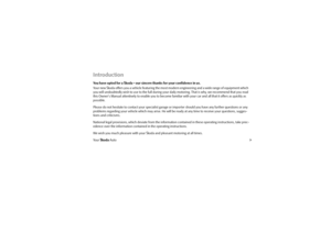 2
2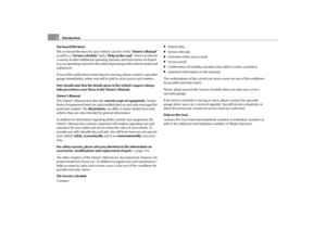 3
3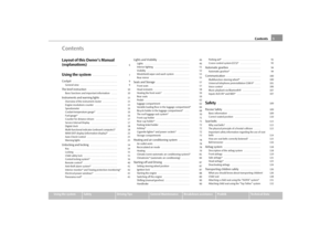 4
4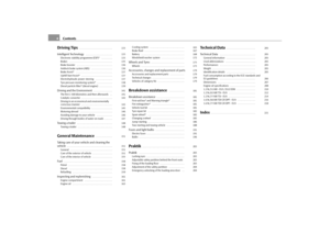 5
5 6
6 7
7 8
8 9
9 10
10 11
11 12
12 13
13 14
14 15
15 16
16 17
17 18
18 19
19 20
20 21
21 22
22 23
23 24
24 25
25 26
26 27
27 28
28 29
29 30
30 31
31 32
32 33
33 34
34 35
35 36
36 37
37 38
38 39
39 40
40 41
41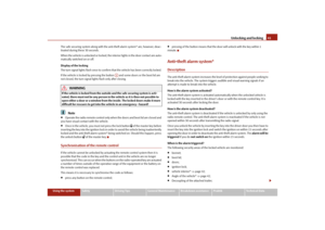 42
42 43
43 44
44 45
45 46
46 47
47 48
48 49
49 50
50 51
51 52
52 53
53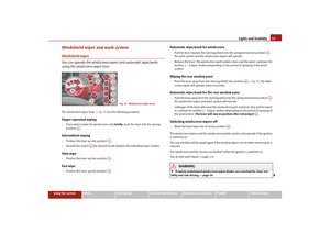 54
54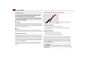 55
55 56
56 57
57 58
58 59
59 60
60 61
61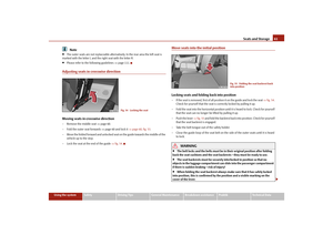 62
62 63
63 64
64 65
65 66
66 67
67 68
68 69
69 70
70 71
71 72
72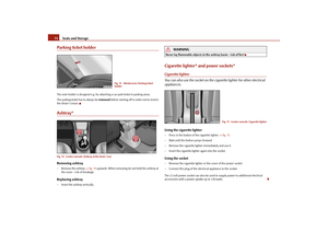 73
73 74
74 75
75 76
76 77
77 78
78 79
79 80
80 81
81 82
82 83
83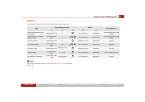 84
84 85
85 86
86 87
87 88
88 89
89 90
90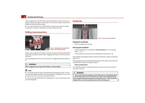 91
91 92
92 93
93 94
94 95
95 96
96 97
97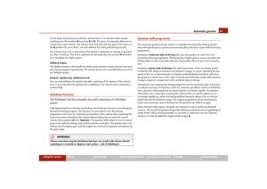 98
98 99
99 100
100 101
101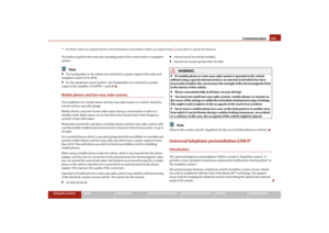 102
102 103
103 104
104 105
105 106
106 107
107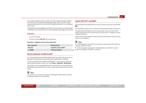 108
108 109
109 110
110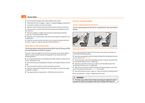 111
111 112
112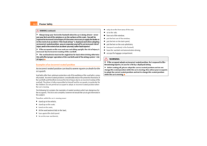 113
113 114
114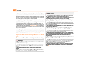 115
115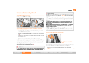 116
116 117
117 118
118 119
119 120
120 121
121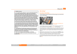 122
122 123
123 124
124 125
125 126
126 127
127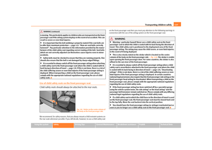 128
128 129
129 130
130 131
131 132
132 133
133 134
134 135
135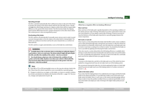 136
136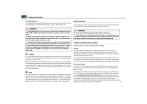 137
137 138
138 139
139 140
140 141
141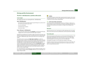 142
142 143
143 144
144 145
145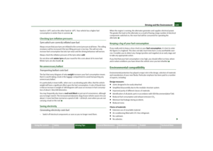 146
146 147
147 148
148 149
149 150
150 151
151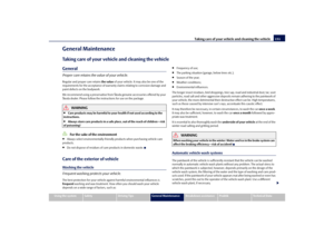 152
152 153
153 154
154 155
155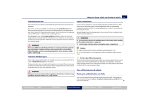 156
156 157
157 158
158 159
159 160
160 161
161 162
162 163
163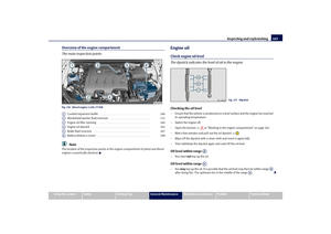 164
164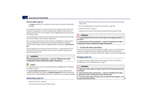 165
165 166
166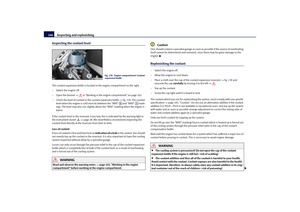 167
167 168
168 169
169 170
170 171
171 172
172 173
173 174
174 175
175 176
176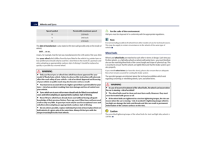 177
177 178
178 179
179 180
180 181
181 182
182 183
183 184
184 185
185 186
186 187
187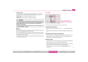 188
188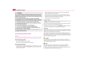 189
189 190
190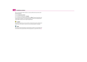 191
191 192
192 193
193 194
194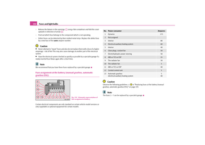 195
195 196
196 197
197 198
198 199
199 200
200 201
201 202
202 203
203 204
204 205
205 206
206 207
207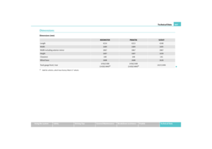 208
208 209
209 210
210 211
211 212
212 213
213 214
214 215
215 216
216 217
217 218
218 219
219 220
220 221
221 222
222 223
223 224
224 225
225 226
226 227
227 228
228 229
229 230
230