Page 49 of 231

Lights and Visibility
48
The adaptation of the halogen projector he adlights must be performed as follows
page 146.Fog lights*
Switching on the fog lights
– First of all turn the light switch into position
or fig. 35 .
– Pull the light switch out to the first detent .
The warning light
l i g h t s u p i n t h e i n s t r u m e n t c l u s t e r when the fog lights are switched
on page 25.
Fog lights with the function “CORNER”*
The fog lights with the function “CORNER” are designed for a better illu-
mination of the surrounding area near the vehicle when corning,
parking etc.The fog lights with the function “CORNER” ar e adjusted according to the steering angle
or after switching on the turn signal light
8) in the following circumstances:
the vehicle is stationary and the engine is running or it moves with a speed of
maximum 40 km/h;
the daylight driving lights are not switched on;
Low beam switched on.
A fault in the system of the fog lights with the function “CORNER” is confirmed by the
warning light
lighting up.
Note
If the fog lights are switched on, the function of the lights “CORNER” is not active.Rear fog light
Switching on the rear fog light– First of all turn the light switch into position
or fig. 35 .
– Pull the switch into position . The fog lights* light up at the same time.
If the vehicle is not fitted with fog lights*, th e rear fog light is switched on by turning the
light switch to the position
and is pulled out directly to the position . This switch
does not have two position s, but only one position.
The warning light
lights up in the instrument cluster when the rear fog light is
switched on page 25.
Only the rear fog light of the trailer lights up if the vehicle is fitted with a towing device
from Škoda original accessories and when you are towing a trailer which is fitted with
the rear fog light.
Caution
The rear fog light should only be switched on if visibility is partic ularly poor (conform
with any varying legal provisions) to avoid dazzling vehicles behind your vehicle.
8)If both switch on versions are conflicting, for example if the steering wheel is turned to the left
and the right turn signal light is switched on, the turn signal light has the higher priority.
Fig. 35 Dash panel: Light switchA1
A2
A2
s16g.4.book Page 48 Wednesda y, February 10, 2010 3:53 PM
Page 50 of 231

Lights and Visibility49
Using the system
Safety
Driving Tips
General Maintenance
Breakdown assistance
Praktik
Technical Data
Headlamp range adjustment
Once the low beam is switched on you can then adapt the range of the
headlights to the lo ad of the vehicle.– Turn the control dial fig. 36 until you have adjusted the low beam so that
oncoming traffic is not dazzled.
Settings
The positions correspond approximately to the following vehicle loads:
Front seats occupied, luggage compartment empty.
All seats occupied, luggage compartment empty.
All seats occupied, luggage compartment laden.
Driver seat occupied, lu ggage compartment laden.
Caution
Set the headlight beam adjustment in su ch a way as to avoid dazzling oncoming
traffic.
Switch for hazard warning lights
– Press switch
fig. 37 to switch the hazard warning light system on or off.
All the turn signal lights on the vehicle flas h at the same time when the hazard warning
light system is switched on. The indicator light for the turn signals and the indicator
light in the switch also flash at the same time. You can also switch on the hazard
warning light system if the ignition is switched off.
The hazard warning light system is switched on automatically if an airbag is deployed
in the event of an accident.
Please comply with any legal requirements when using the hazard warning light
system.
Note
Switch on the hazard warning light system if, for example:
you encounter traffic congestion;
your vehicle breaks down or an emergency situation occurs.
Fig. 36 Dash panel: Lights and Visibility
A-A1A2A3
Fig. 37 Dash panel: Switch for hazard
warning lights
s16g.4.book Page 49 Wednesda y, February 10, 2010 3:53 PM
Page 51 of 231

Lights and Visibility
50
The turn signal
and main beam lever
The parking lights and headlight flas her are also switched on and off
using the turn signal and main beam lever.The turn signal and main beam le ver perform the following functions:Right
and left
turn signal light
– Push the lever upwards or downwards fig. 38 .
– If you only wish to flash three times (the so-called convenience turn signal*), push
the lever briefly up to the upper or lower pressure point and release it.
– Turn signal for changing lanes - in order to only flash briefly, move the lever up or
down to the pressure point and hold it in this position.Main beam
– Switch on the low beam.
– Push the lever forwards.
– Pull the lever back into the initial positi on in order to switch the main beam off
again.Headlight flasher
– Pull the lever towards the steering wheel (spring-tensioned position) - the main beam and warning light
in the instrument cluster come on.
Parking light
– Switch off the ignition.
– Push the lever up or down - the right-hand or left-hand parking light is switched
on.
Information concerning the function of the lights.
The turn signal system only operates when the ignition is switched on. The corre-
sponding warning light
or in the instrument cluster also flashes.
The turn signal is automatically cancelled after negotiating a curve.
The side light and rear light on the appropriate side of the vehicle are switched on
when the parking light is selected. The parking light function only operates if the igni-
tion is switched off.
An acoustic warning signal will sound when the driver's door is opened if the lever
is not in the middle position after removing the ignition key from the ignition lock. The
acoustic warning signal will stop just as soon as the driver's door is closed.Caution
Use main beam or the headlight flasher only if this does not risk dazzling other road
users.
Note
If you have switched on the right or left turn signal light and you switch off the igni-
tion, the parking light is no t automatically switched on.
Use only in accordance with the legal requirements the described lighting and
signal systems.
Fig. 38 Turn signal and main beam lever
s16g.4.book Page 50 Wednesda y, February 10, 2010 3:53 PM
Page 52 of 231

Lights and Visibility51
Using the system
Safety
Driving Tips
General Maintenance
Breakdown assistance
Praktik
Technical Data
Interior lightingFront interior lighting and storage compartment on front passenger sideDoor contact switching mechanism (front and rear* doors)– Press the switch
to the right into position fig. 39 .
– On the version without reading lights press the switch into the middle position
.
Switching the interior light on– Press the switch to the left into position
.
Switching the interior light off– Press the switch into the middle position O.
– On the version without reading lights press the switch to the right, the symbol O appears.Reading lights
– Press on one of the switches fig. 39 in order to switch the right or left reading
light on or off.
Lighting of storage compartme nt on the front passenger side– When opening the flap of the storage compartment on the front passenger side the
lighting in the storage compartment comes on.
– The light switches on automatically when the parking light is switched on and goes
out when the flap is closed.
On vehicles with central locking, the interior light is switched on for about 30 seconds
when the vehicle is unlocked, when a door is opened or after withdrawing the ignition
key (if the relevant switch is in the door contact position). The inner light goes out out
immediately after the ignition is switched on.
A time delay switch* causes the inner lighting on vehicles without a central locking
system stays on for a few seconds after the doors have been closed. The inner light
goes out out immediately after the ignition is switched on.
The interior lighting is switched off after about 10 minutes when a door has been left
open in order to avoid discharg ing the battery of the vehicle.Rear interior lighting*The rear interior lighting fig. 40 is actuated by moving the switch to the symbol
,
O or to the middle position
.
The same principles apply for th e interior lighting at the rear as for the for the interior
lighting at the front page 51.
Fig. 39 Detail of the headliner: front
interior lighting
AA
AA
AAAA
AA
AB
Fig. 40 Roof liner light
s16g.4.book Page 51 Wednesda y, February 10, 2010 3:53 PM
Page 53 of 231

Lights and Visibility
52Note
We recommend having the bulb replaced by a specialist garage.Luggage compartment lightThe lighting comes on automatically when th e boot lid is opened. If the lid remains
open for more than about 10 minutes, the luggage compartment lighting switches off
automatically.VisibilityRear window heater– You can switch the rear window heater on or off by pressing the switch
fig. 41 - the indicator light in the switch comes on or goes out.
The rear window heater only operates when the engine is running.
The rear wind ow heater switches off automatically after 7 minutes.
If the on-board voltage drops, the rear window heater is switched off automatically, the
warning light flashes in the button.
For the sake of the environment
As soon as the window is de-iced or free fr om mist, the heating should be switched off.
The reduced current consumption will have a favourable effect on fuel economy
page 145, “Saving electricity”.Sun visorsYou can pull the sun visor for the driver or front passenger out of the fixture and swivel
it toward the door in the direction of the arrow fig. 42 .
The vanity mirrors* for the driver and front passenger, which are integrated in the sun
visors, are provided with covers. Push the cover in direction of arrow .
WARNING
The sun visors must not be swivelled to the side windows into the deployment
area of the head airbags if any objects, su ch as ball-point pens etc. are attached
to them. This might result in injuries to the occupants if the head airbag is
deployed.
Fig. 41 Switch for rear window heater
Fig. 42 Sun visor: swivelling outA1
A2
s16g.4.book Page 52 Wednesda y, February 10, 2010 3:53 PM
Page 54 of 231

Lights and Visibility53
Using the system
Safety
Driving Tips
General Maintenance
Breakdown assistance
Praktik
Technical Data
Windshield wiper and wash systemWindshield wiper
You can operate the windscreen wipers and automatic wipe/wash
using the windscreen wiper lever.The windscreen wiper lever fig. 43 has the following positions:Finger-operated wiping– If you wish to wipe the windscreen only briefly, push the lever into the sprung
position .Intermittent wiping– Position the lever up into position .
– Set with the switch the desired brea k between the individual wiper strokesSlow wipe– Position the lever up into position .Fast wipe– Position the lever up into position .
Automatic wipe/wash for windscreen– Pull the lever towards the steering wheel into the spring-tensioned position ,
the wash system and the windscreen wipers will operate.
– Release the lever. The windscreen wash system stops and the wiper continues for another 1 - 3 wiper strokes (depending on the period of spraying of the wind-
screen).Wiping the rear window pane– Push the lever away from the st eering wheel into position fig. 43 , the wide-
screen wiper will operate every 6 seconds.Automatic wipe/wash for the rear window pane– Push the lever away from the steering wheel into the spring-tensioned position , the windscreen wiper and wash system will operate.
– Letting go of the lever will cause the windscreen wash system to stop and the wiper to continue for another 1 - 3 wiper strokes (depending on the period of spraying of
the windscreen). The lever will stay in position after releasing it .Switching windscreen wipers off– Move the lever back into its home position .
The windscreen wipers and the windscreen washer system only operate if the ignition
is switched on.
The rear window will be wiped again if the window wipers are on when reverse gear is
selected.
The windscreen washer nozzles are heated* when the ignition is switched on.
Top up with wash liquid page 172.
WARNING
Properly maintained windscreen wiper blades are essential for clear visi-
bility and safe driving page 54.
Fig. 43 Windscreen wiper lever
A4
A1
AA
A2A3
A5
A6
A7
A6
A0
s16g.4.book Page 53 Wednesda y, February 10, 2010 3:53 PM
Page 55 of 231

Lights and Visibility
54
Do not use the windscreen washer sy stem at low temperatures, without
heating the windscreen beforehand. Otherwise the window cleaner could
freeze on the windscreen and re strict the view to the front.
In the event of a freezing up of the wi ndscreen, first of all eliminate the ice
page 153 and then operate the windscr een wiper otherwise the windscreen
wiper blades could be damaged.Caution
In frosty weather, please firs t of all check whether the windscreen wiper blades are not
frozen to the windscreen before switching them on. Switching on windscreen wipers
when the blades are frozen to the windscreen may result in damage both to the blades
and the motor of the windscreen wipers!
Note
The content of the windscreen wiper reserv oir is 3.5 litres. On vehicles which are
equipped with a headlight cleaning system*, the content of the reservoir is 5.4 litres.Headlight cleaning system*The headlights are being cleaned after the windscreen washer system has been oper-
ated for the fifth time, the low beam or main beam are switched on as well as the wind-
screen wiper lever is held in the position page 53, fig. 43 for about 1 second.
You should remove stubborn dirt (such as in sect residues) from the headlight lenses at
regular intervals, for example when refuelling . Please refer to the following guidelines
page 154, “The headlight lenses”.
You should remove any snow from the fixtur es of the washer nozzles and clear ice in
winter with a de-icing spray in order to ensure proper operation of the cleaning
system.
Replacing wiper blades for the windscreen wipersTaking off the wiper blade– Fold windscreen wiper arm away from the windscreen.
– Press the locking button, in order to un lock the wiper blade and pull off in the
direction of arrow.Attaching a wiper blade– Push the wiper blade until it locks up to the stop.
– Check whether the wiper blade is correctly attached.
– Fold the windscreen wiper ar m back onto the windscreen.
Wiper blades in proper condition are essentia l to obtain good visibility. Wiper blades
should not be allowed to become dirtied by dust, insect remains and preserving wax.
Juddering or smearing of the wiper blades co uld then be due to wax residues left on
the windscreen by vehicle washing in automa tic vehicle wash systems. It is therefore
important to degrease the lips of the wiper blades after every pass through an auto-
matic vehicle wash system .
WARNING
If the windscreen wipers are handled ca relessly, there is a risk of damage to
the windscreen.
WARNING (continued)
A5
Fig. 44 Wiper blade for the windscreen
wiper
s16g.4.book Page 54 Wednesda y, February 10, 2010 3:53 PM
Page 56 of 231

Lights and Visibility55
Using the system
Safety
Driving Tips
General Maintenance
Breakdown assistance
Praktik
Technical Data
You should clean the wiper blades regularly with a windscreen cleaner in
order to avoid any smears. Clean a wiper blad e with a sponge or cloth if it is very
dirty, for example from insect residues.
Replace the wiper blades once or twice a year for safety reasons. The wiper
blades are available from specialist garages.
Replacing the wiper blade on the rear window wiperTaking off the wiper blade– Fold windscreen wiper arm out from the windscreen and position the wiper blade at right angles to the wiper arm fig. 45 .
– Hold the window wiper arm at the top end with one hand.
– With the other hand unlock the locking button in the direction of arrow and remove the wiper blade.Attaching a wiper blade– Position the wiper blade onto the wiper arm and lock the locking button .
– Check whether the wiper bl ade is correctly attached.
The same remarks apply here as for page 54.
Rear mirrorYou can adjust the exterior mirrors electrically*.Adjust the rear mirror before commencing to drive so that there is a clear view to the
rear.Dimming the interior mirror– Pull the lever on the bottom edge of the mirror toward rear (the lever on the inte-
rior mirror must point forwards in it home position).Heating of the external mirror*– Turn the rotary knob to position
fig. 46 .
Adjusting the left-hand exterior mirror*– Turn the rotary knob to position
. The movement of the mirror surface is identical
to the movement of the rotary knob.
Adjusting the right-hand exterior mirror*– Turn the rotary knob to position
. The movement of the mirror surface is identical
to the movement of the rotary knob.
The vehicle can also be equipp ed with a second rear mirror*, which is attached above
the inner main rear mirror. The second rear mirror* enables an extensive look into the
area of the rear seats, e.g. to check on the seated passengers. You can adjust it in the
horizontal as well as vertical direction re gardless of the inner main rear mirror.
WARNING (continued)
Fig. 45 Wiper blade for rear windowAA
AA
Fig. 46 Inner part of door: Rotary knob
s16g.4.book Page 55 Wednesday, February 10, 2010 3:53 PM
 1
1 2
2 3
3 4
4 5
5 6
6 7
7 8
8 9
9 10
10 11
11 12
12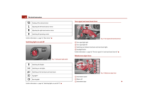 13
13 14
14 15
15 16
16 17
17 18
18 19
19 20
20 21
21 22
22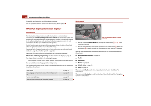 23
23 24
24 25
25 26
26 27
27 28
28 29
29 30
30 31
31 32
32 33
33 34
34 35
35 36
36 37
37 38
38 39
39 40
40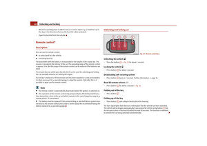 41
41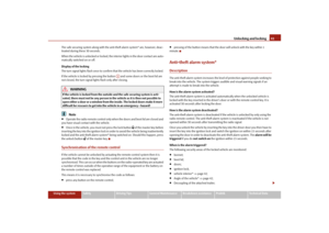 42
42 43
43 44
44 45
45 46
46 47
47 48
48 49
49 50
50 51
51 52
52 53
53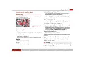 54
54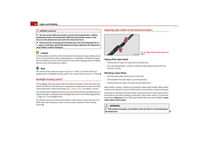 55
55 56
56 57
57 58
58 59
59 60
60 61
61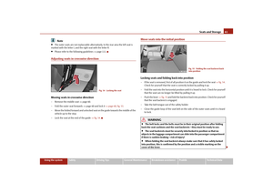 62
62 63
63 64
64 65
65 66
66 67
67 68
68 69
69 70
70 71
71 72
72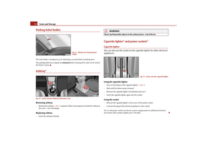 73
73 74
74 75
75 76
76 77
77 78
78 79
79 80
80 81
81 82
82 83
83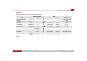 84
84 85
85 86
86 87
87 88
88 89
89 90
90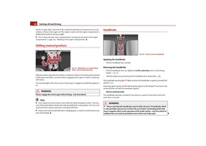 91
91 92
92 93
93 94
94 95
95 96
96 97
97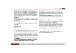 98
98 99
99 100
100 101
101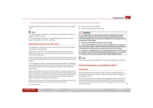 102
102 103
103 104
104 105
105 106
106 107
107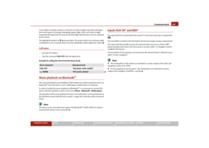 108
108 109
109 110
110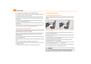 111
111 112
112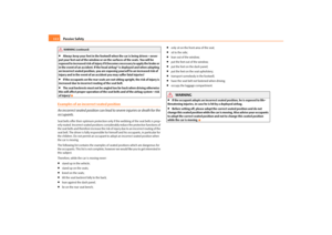 113
113 114
114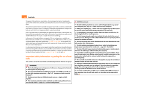 115
115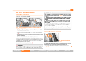 116
116 117
117 118
118 119
119 120
120 121
121 122
122 123
123 124
124 125
125 126
126 127
127 128
128 129
129 130
130 131
131 132
132 133
133 134
134 135
135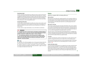 136
136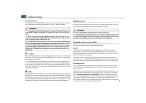 137
137 138
138 139
139 140
140 141
141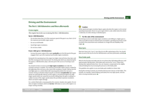 142
142 143
143 144
144 145
145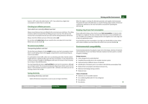 146
146 147
147 148
148 149
149 150
150 151
151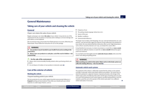 152
152 153
153 154
154 155
155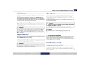 156
156 157
157 158
158 159
159 160
160 161
161 162
162 163
163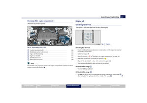 164
164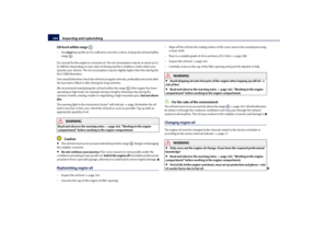 165
165 166
166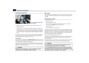 167
167 168
168 169
169 170
170 171
171 172
172 173
173 174
174 175
175 176
176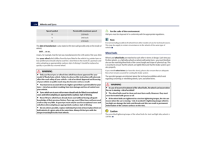 177
177 178
178 179
179 180
180 181
181 182
182 183
183 184
184 185
185 186
186 187
187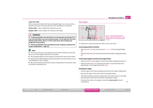 188
188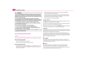 189
189 190
190 191
191 192
192 193
193 194
194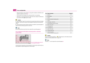 195
195 196
196 197
197 198
198 199
199 200
200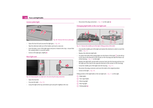 201
201 202
202 203
203 204
204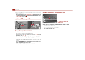 205
205 206
206 207
207 208
208 209
209 210
210 211
211 212
212 213
213 214
214 215
215 216
216 217
217 218
218 219
219 220
220 221
221 222
222 223
223 224
224 225
225 226
226 227
227 228
228 229
229 230
230