Page 201 of 231

Fuses and light bulbs
200
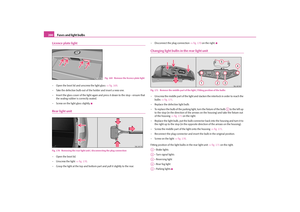
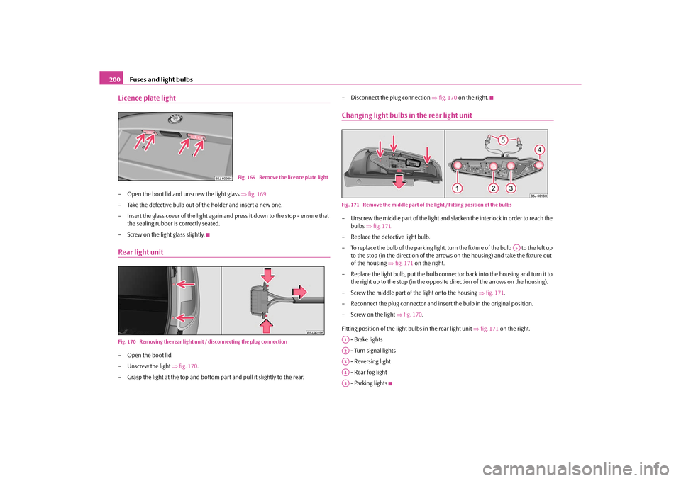
Licence plate light– Open the boot lid and unscrew the light glass fig. 169 .
– Take the defective bulb out of the holder and insert a new one.
– Insert the glass cover of the light again and press it down to the stop - ensure that
the sealing rubber is correctly seated.
– Screw on the light glass slightly.Rear light unitFig. 170 Removing the rear light uni t / disconnecting the plug connection– Open the boot lid.
– Unscrew the light fig. 170 .
– Grasp the light at the top and bottom pa rt and pull it slightly to the rear. – Disconnect the plug connection
fig. 170 on the right.
Changing light bulbs in the rear light unitFig. 171 Remove the middle part of the light / Fitting position of the bulbs– Unscrew the middle part of the light and slacken the interlock in order to reach the
bulbs fig. 171 .
– Replace the defective light bulb.
– To replace the bulb of the parking light, turn the fixture of the bulb to the left up to the stop (in the direction of the arrows on the housing) and take the fixture out
of the housing fig. 171 on the right.
– Replace the light bulb, put th e bulb connector back into the housing and turn it to
the right up to the stop (in the opposite direction of the arrows on the housing).
– Screw the middle part of the light onto the housing fig. 171 .
– Reconnect the plug connector and insert the bulb in the original position.
– Screw on the light fig. 170 .
Fitting position of the light bulbs in the rear light unit fig. 171 on the right.
- Brake lights
- Turn signal lights
- Reversing light
- Rear fog light
- Parking lights
Fig. 169 Remove the licence plate light
A5
A1A2A3A4A5
s16g.4.book Page 200 Wednesda y, February 10, 2010 3:53 PM
Page 202 of 231
Fuses and light bulbs201
Using the system
Safety
Driving Tips
General Maintenance
Breakdown assistance
Praktik
Technical Data
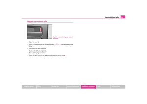
Luggage compartment light– Open the boot lid.
– Insert a screwdriver into the slot below the light fig. 172 . Lever out the light care-
fully.
– Disconnect the plug connector.
– Replace the defective light bulb.
– Recreate the plug connection.
– Insert the light from the rear and press it forwards up to the stop.
Fig. 172 Remove the luggage compart-
ment light
s16g.4.book Page 201 Wednesda y, February 10, 2010 3:53 PM
Page 203 of 231
Fuses and light bulbs
202
s16g.4.book Page 202 Wednesda y, February 10, 2010 3:53 PM
Page 204 of 231
Praktik203
Using the system
Safety
Driving Tips
General Maintenance
Breakdown assistance
Praktik
Technical Data
PraktikPraktikLashing eyesEyes are located on the sides of the loading area for lashing the load to be loaded
fig. 173 .
WARNING
The load to be transported must be fixed in place in such a way that it cannot
move during the journey and when braking.
Adjustable safety partition behind the front seatsThe adjustable safety partition behind the front seats can be adjusted up to 100 mm
(only valid for certain countries) for improving the comfort for the driver and the front
passenger.Fixing of the loading floorFig. 175 Loop for raising the loading floor / Fixing the loading floor with a plastic hook
Fig. 173 Loading area: Lashing eyes
Fig. 174 Adjustable safety partition
s16g.4.book Page 203 Wednesday, February 10, 2010 3:53 PM
Page 205 of 231

Praktik
204
You can fix the loading floor with a hook on th e top edge of the boot lid cutout, in order
to e.g. reach the spare wheel*.
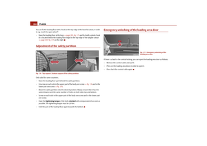
– Raise the loading floor at the loop page 203, fig. 175 and fix it with a plastic hook
(it is located below the loading floor edge) to the top edge of the tailgate cutout
page 203, fig. 175 on the right.Adjustment of the safety partitionFig. 176 Top support / bottom support of the safety partitionOnly valid for some countries.
– Raise the loading floor part behind the safety partition.
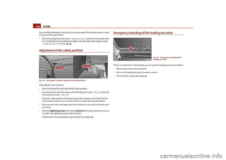
– Unscrew on each side in the u pper part of the body one screw fig. 176 and in the
lower part one screw fig. 176 .
– Move the safety partition into the desired position. Always ensure that it has the same distance and the same number of holes on both sides top and bottom.
– Screw on each side in the upper part of the body one screw and in the lower part one screw.
–Have the tightening torque of the bolts checked with a torque wrench as soon as
possible. The tightening torque must be 20 Nm.
– Fold the part of the loading floor again towards the bottom.
Emergency unlocking of the loading area doorIf there is a fault in the central locking, you can open the loading area door as follows:
– Remove the control cable and pull it.
– Press on the loading area door, in order to open it.
– Press back the control cable again.
Fig. 177 Emergency unlocking of the
loading area door
s16g.4.book Page 204 Wednesda y, February 10, 2010 3:53 PM
Page 206 of 231

Technical Data205
Using the system
Safety
Driving Tips
General Maintenance
Breakdown assistance
Praktik
Technical Data
Te c h n i c a l D a t aTechnical DataGeneral informationThe details given in the official vehicle regi stration documents always take precedence
over the details in the Owner's Manual. Please refer to the official vehicle registration
documents or consult a specialist garage concerning the engine with which your
vehicle is equipped.Used abbreviations
PerformancesThe listed performance values were de termined without performance-reducing
equipment, e.g. air conditioning system.WeightThe loading capacity is reduced in line with the range of the special equipment. The
unloaden weight contains a fuel tank topped up to 90%. A driver with a weight of 75
kg is also includ ed in the value.Identification detailsVehicle data sticker
The vehicle data sticker fig. 178 is located on the floor of the luggage compartment
and is also stated in the Service schedule.
The vehicle data sticker co ntains the following data:
Vehicle identification number (VIN)
Vehicle type
Abbreviation
Importance
kW
Kilowatt, measuring unit for the engine output
rpm
Engine revolutions per minute
Nm
Newton meter, measuring unit for the engine torque
g/km
discharged quantity of carbon dioxide in grams per driven
kilometer
TSI
Petrol engine with a turbocharger and a direct fuel injection
system
TDI CR
Diesel engine with turbocharger and injection system Com-
mon Rail
M5
5-speed manual gearbox
DQ7
7-speed automatic gearbox DSG
DPF
Diesel particle filter
Fig. 178 Vehicle data sticker
A1A2
s16g.4.book Page 205 Wednesda y, February 10, 2010 3:53 PM
Page 207 of 231

Technical Data
206Gearbox code, paint number, interior eq uipment number, engine output, engine
code
Partial description of the vehicle
7GG, 7MB, 7MG - vehicles with DPF page 139
Vehicle identification number (VIN)
The vehicle identification number - VIN (veh icle body number) is stamped into the
engine compartment on the right hand sh ock absorber dome. This number is also
located on a sign on the lowe r left hand edge below the windscreen (together with a
VIN bar code).
Engine number
The engine number is stam ped into the engine block.
Type plate (production plate)
The type plate is located in the engine compartment at the front on the left hand shock
absorber dome.
Sticker on inside of fuel filler flap
The sticker is affixed to the inside of the fuel filler flap. They contain the following data:
the prescribed type of fuel;
tyre size;
Tyre pressure.
Fuel consumption according to the ECE standards and EU guidelinesDepending on the range of the special equipment, style of driving, traffic situation,
weather influences and vehicl e condition, the consumption values which in practice
result when using the vehicle can deviate from the indicated values.
Urban traffic
The consumption measurement in urban traffic begins with starting of the cold engine.
Afterwards the normal ur ban traffic is simulated. Non-urban traffic
For the consumption measurement in non-ur
ban traffic the vehicle, as in daily
motoring, is accelerated and braked severa l times in all gears. The vehicle speed
changes within the range from 0 to 120 km/h.
Combined traffic
The consumption value in the combined traffic consists of 37% from the value for the
urban traffic and of 63% from th e value for the non-urban traffic.
Note
Please note that the information stated in the official vehicle registration docu-
ments always takes priority.
A3A4A5s16g.4.book Page 206 Wednesda y, February 10, 2010 3:53 PM
Page 208 of 231
Technical Data207
Using the system
Safety
Driving Tips
General Maintenance
Breakdown assistance
Praktik
Technical Data
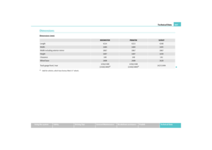
DimensionsDimensions (mm)
ROOMSTER
PRAKTIK
SCOUT
Length
4214
4213
4240
Width
1684
1684
1695
Width including exterior mirror
1867
1867
1867
Height
1607
1607
1650
Clearance
140
140
141
Wheel base
2608
2608
2620
Track gauge front / rear
1436/1500
(1420/1484)
a)
a)Valid for vehicles, which ha ve factory-fitted 15" wheels.
1436/1500
(1420/1484)
a)
1427/1494
s16g.4.book Page 207 Wednesda y, February 10, 2010 3:53 PM