2010 JAGUAR XFR height
[x] Cancel search: heightPage 484 of 3039

each damper to the appropriate level to maintain a flat and level body.
Roll Rate Control – Uses CAN inputs. Predicts vehicle roll rate due to driver steering inputs 100 times a second and increases damping to reduce roll rate.
Pitch Rate Control – Uses CAN inputs. Predicts vehicle pitch rate due to driver throttle and braking inputs 100 times a second and increases damping to reduce pitch rate.
Bump Rebound Control – Uses suspension height sensor and CAN inputs. Monitors the position of the wheel 500 times a second and increases the damping rate as the damper approaches the end of its travel.
Wheel Hop Control – Uses suspension height sensor and CAN inputs. Monitors the position of the wheel 500 times a second and detects when the wheel is at its natural frequency and increases the dampingto reduce vertical wheel
motion.
Under normal road conditions when the vehicle is stationary with the engine running, the dampers are set to the firm condition
to reduce power consumption.
The adaptive damping module receives its power supply via a relay and fuse in the CJB. The relay remains energized for a period of time after the ignition is off. This allows the adaptive damping module to record and store any DTC (diagnostic
trouble code) relating to adaptive dynamics system faults.
DAMPERS Component Description
Item Description A Front spring and damper assembly B Rear spring and damper assembly The 'Adaptive Dynamics' dampers are monotube, nitrogen gas and oil filled units, manufactured by Bilstein. The dampers are
continuously variable, which allows the damping force to be electrically adjusted when the vehicle is being driven. The variable
dampers provide the optimum compromise between vehicle control and ride comfort.
The dampers have an electrical connector on the end of the piston rod, in the center of the top mount (the dampers look
identical to those on the Computer Active Technology Suspension (CATS) system of 4.2L supercharged vehicles, but have a
different part number).
In each damper, the continuous damping adjustment is achieved by a solenoid operated variable orifice, which opens up an
alternative path for oil flow within the damper. When de-energized the bypass is closed and all the oil flows through the main
(firm) piston. When energized, the solenoid moves an armature and control blade, which work against a spring. The control
blade incorporates an orifice which slides inside a sintered housing to open up the bypass as required. In compression, oil
flows from the lower portion of the damper through a hollow piston rod, a separate soft (comfort) valve, the slider housing and
orifice and into the upper portion of the damper, thereby bypassing the main (firm) valve. In rebound the oil flows in the www.JagDocs.com
Page 486 of 3039

2 Main piston 3 Tube 4 Bypass valve (closed) 5 Piston and rod assembly ACCELEROMETERS
Three accelerometers are used in the adaptive dynamics system. The accelerometers are located as follows:
One each on the rear edge of the radiator support panel.
One in the luggage compartment, in the rear LH corner adjacent to the rear lamp assembly.
The accelerometers measure acceleration in the vertical plane and output a corresponding analogue signal to the adaptive
damping module. The algorithms in the adaptive damping module calculate the heave, pitch and roll motions of the vehicle,
which are used by the module to control road induced body modes.
Each accelerometer is connected to the adaptive damping module via three wires, which supply ground, 5 V supply and signal
return.
The sensing element comprises a single parallel plate capacitor, one plate of which moves relative to the other dependant on
the force (acceleration) applied. This causes the capacitance to change as a function of applied acceleration. This capacitance
is compared with a fixed reference capacitor in a bridge circuit and the signal is processed by means of a dedicated integrated
circuit to generate an output voltage that varies as a function of applied acceleration. The sensors output a signal voltage of
approximately 1 V/g ± 0.05 V/g.
SUSPENSION HEIGHT SENSORS
Four suspension height sensors are used in the adaptive dynamics system, two for the front suspension and two for the rear
suspension. A front suspension height sensor is attached to each side of the front subframes and connected by a sensor arm
and sensor link to the related lower lateral arm of the front suspension. A rear suspension height sensor is attached to each
side of the rear subframe and connected by a sensor arm and sensor link to the related upper control arm of the rear
suspension. On each suspension height sensor, the sensor arm and sensor link convert linear movement of the suspension into
rotary movement of the sensor shaft.
The sensors are also used for the static dynamic headlamp leveling system on vehicles fitted with xenon headlamps.
The suspension height sensors measure suspension displacement at each corner of the vehicle and output a corresponding
analogue signal to the adaptive damping module. The algorithms in the adaptive damping module calculate the position,
velocity and frequency content of the signals and use the results for wheel control.
Each suspension height sensor is connected to the adaptive damping module via three wires, which supply ground, 5 V supply
Page 488 of 3039

Vehicle Dynamic Suspension - Vehicle Dynamic Suspension
Diagnosis and Testing
Principle of Operation Published: 09-Jul-2014
For a detailed description of the adaptive damping system operation, refer to the relevant Description and Operation section of
the workshop manual. REFER to: (204-05 Vehicle Dynamic Suspension)
Vehicle Dynamic Suspension - V8 5.0L Petrol/V8 S/C 5.0L Petrol (Description and Operation),
Inspection and Verification
1. Verify the customer concern.
2. Visually inspect for obvious signs of damage and system integrity.
Visual Inspection
Mechanical Electrical
Coil spring(s)
Shock absorber(s)
Accelerometer(s) installation
Height sensor(s) installation
Fuse(s)
Wiring harness/electrical connectors
Accelerometer(s)
Adaptive Damping Control Module
Height sensor(s)
3. If an obvious cause for an observed or reported concern is found, correct the cause (if possible) before proceeding to
the next step.
4. If the cause is not visually evident, check the system for any logged Diagnostic Trouble Codes (DTCs) and refer to the
DTC index.
DTC Index
For a list of Diagnostic Trouble Codes (DTCs) that could be logged on this vehicle, please refer to Section 100-00.
REFER to: Diagnostic Trouble Code (DTC) Index - DTC: Adaptive Damping Module (SUMB) (100-00 General Information, Description and Operation).
Page 502 of 3039

Symptom Possible Cause Action rear drive halfshaft
Wheel bearings, brakes or
suspension components Vibration at highway speeds
Out-of-balance wheel(s) or tire(s)
Driveline out of
balance/misalignment
Driveshaft center bearing touching
body mounting point
Balance and install new wheel(s) and tire(s)
as required
REFER to: Wheel and Tire (204-04 Wheels and Tires, Removal and Installation).
For additional information,
REFER to: Driveline Angle Inspection (205-00 Driveline System - General Information,
General Procedures).
Refer to the Manufacturer approved
diagnostic system for driveshaft balancing
application
Check for correct spacer washer thickness.
Inspect and install new washers as required Shudder, Vibration During
Acceleration
Powertrain/driveline misalignment
High constant velocity (CV) joint
operating angles caused by
incorrect ride height
Check for misalignment. Install new
components as required. For driveshaft
alignment,
REFER to: Driveline Angle Inspection (205-00 Driveline System - General Information,
General Procedures).
Check the ride height and verify the correct
spring rate. Install new components as
required Lubricant Leak
Rear drive axle breather
Damaged seal
Rear drive axle filler plug
Rear drive axle rear cover joint
Check oil level and correct as required
Install new components as required Pinpoint Tests
PINPOINT TEST A : EXCESSIVE DRIVELINE NOISE TEST
CONDITIONS DETAILS/RESULTS/ACTIONS A1: CHECK NOISE FROM VEHICLE ON ROAD TEST 1 Road test vehicle to determine load and speed conditions when noise occurs. 2 Assess the noise with different gears selected. Does the noise occur in different gears at the same vehicle speed? Yes
Install a new rear drive axle/differential assembly.
REFER to: Axle Assembly - V6 3.0L Petrol (205-02 Rear Drive Axle/Differential, Removal and Installation).
Re-test the system for normal operation.
No
Suspect the engine or transmission. For additional information, REFER to:
Engine - 3.0L/4.2L (303-00 Engine System - General Information, Diagnosis and Testing), Engine - 2.7L Diesel (303-00 Engine System - General Information, Diagnosis and Testing), Diagnostic Strategy (307-01A Automatic Transmission/Transaxle - V6 3.0L Petrol, Diagnosis and Testing).
Page 825 of 3039

Published: 11-May-2011
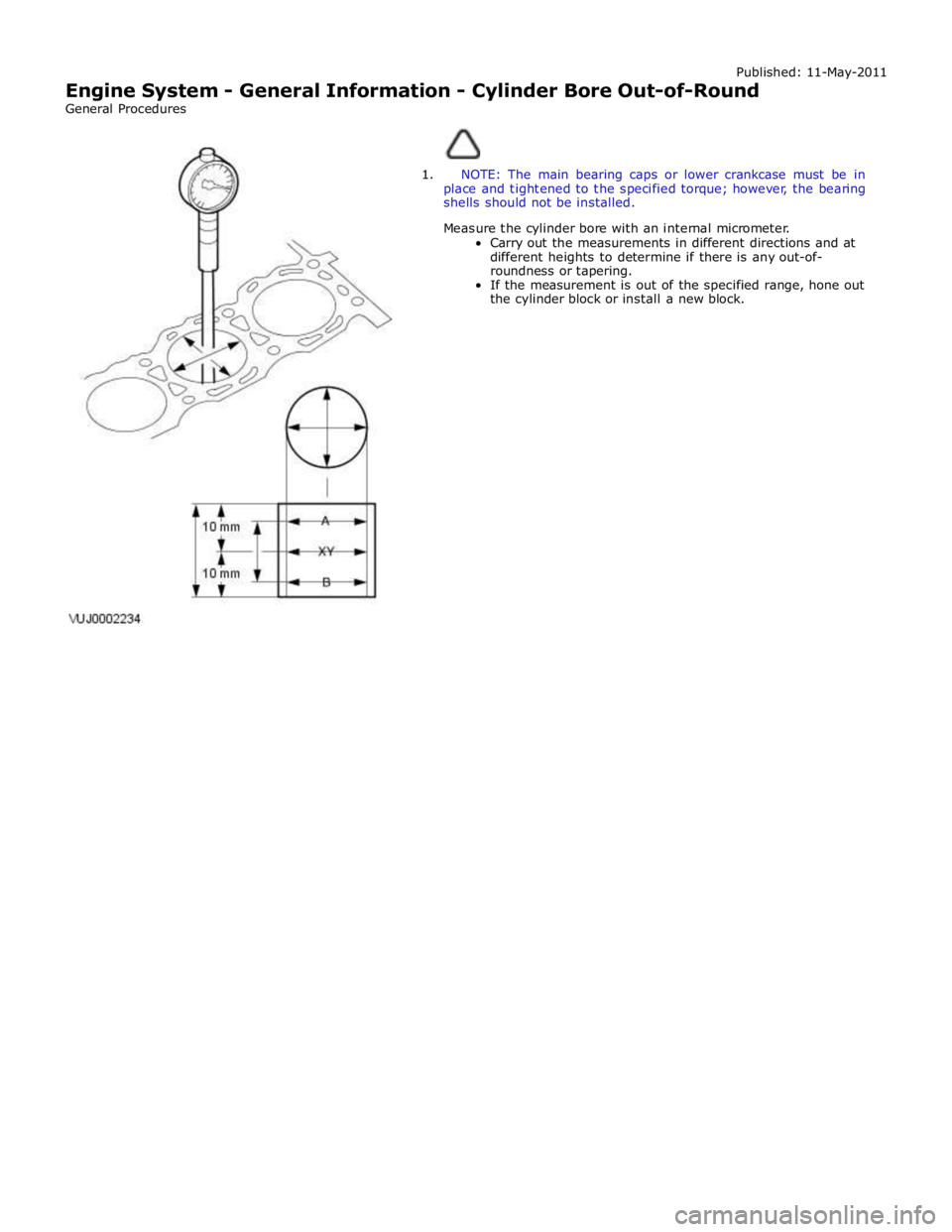
Engine System - General Information - Cylinder Bore Out-of-Round
General Procedures
1. NOTE: The main bearing caps or lower crankcase must be in
place and tightened to the specified torque; however, the bearing
shells should not be installed.
Measure the cylinder bore with an internal micrometer.
Carry out the measurements in different directions and at
different heights to determine if there is any out-of-
roundness or tapering.
If the measurement is out of the specified range, hone out
the cylinder block or install a new block.
Page 844 of 3039

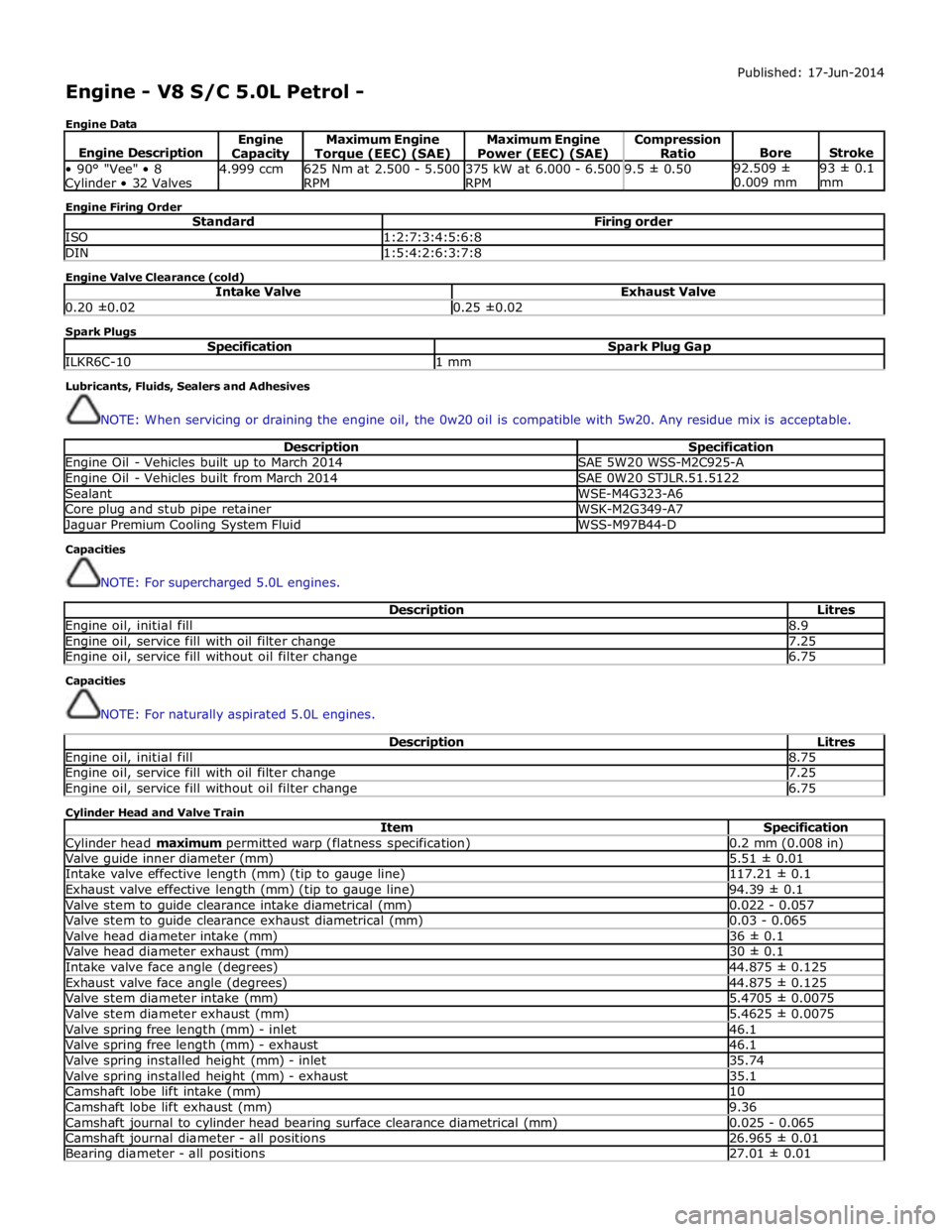
Engine - V8 S/C 5.0L Petrol -
Engine Data Published: 17-Jun-2014
Engine Description Engine Capacity Maximum Engine Torque (EEC) (SAE) Maximum Engine
Power (EEC) (SAE) Compression
Ratio
Bore
Stroke • 90° "Vee" • 8 Cylinder • 32 Valves 4.999 ccm
625 Nm at 2.500 - 5.500
RPM 375 kW at 6.000 - 6.500
RPM 9.5 ± 0.50 92.509 ±
0.009 mm 93 ± 0.1
mm Engine Firing Order
Standard Firing order ISO 1:2:7:3:4:5:6:8 DIN 1:5:4:2:6:3:7:8 Engine Valve Clearance (cold)
Intake Valve Exhaust Valve 0.20 ±0.02 0.25 ±0.02 Spark Plugs
Specification Spark Plug Gap ILKR6C-10 1 mm Lubricants, Fluids, Sealers and Adhesives
NOTE: When servicing or draining the engine oil, the 0w20 oil is compatible with 5w20. Any residue mix is acceptable.
Description Specification Engine Oil - Vehicles built up to March 2014 SAE 5W20 WSS-M2C925-A Engine Oil - Vehicles built from March 2014 SAE 0W20 STJLR.51.5122 Sealant WSE-M4G323-A6 Core plug and stub pipe retainer WSK-M2G349-A7 Jaguar Premium Cooling System Fluid WSS-M97B44-D Capacities
NOTE: For supercharged 5.0L engines.
Description Litres Engine oil, initial fill 8.9 Engine oil, service fill with oil filter change 7.25 Engine oil, service fill without oil filter change 6.75 Capacities
NOTE: For naturally aspirated 5.0L engines.
Description Litres Engine oil, initial fill 8.75 Engine oil, service fill with oil filter change 7.25 Engine oil, service fill without oil filter change 6.75 Cylinder Head and Valve Train
Item Specification Cylinder head maximum permitted warp (flatness specification) 0.2 mm (0.008 in) Valve guide inner diameter (mm) 5.51 ± 0.01 Intake valve effective length (mm) (tip to gauge line) 117.21 ± 0.1 Exhaust valve effective length (mm) (tip to gauge line) 94.39 ± 0.1 Valve stem to guide clearance intake diametrical (mm) 0.022 - 0.057 Valve stem to guide clearance exhaust diametrical (mm) 0.03 - 0.065 Valve head diameter intake (mm) 36 ± 0.1 Valve head diameter exhaust (mm) 30 ± 0.1 Intake valve face angle (degrees) 44.875 ± 0.125 Exhaust valve face angle (degrees) 44.875 ± 0.125 Valve stem diameter intake (mm) 5.4705 ± 0.0075 Valve stem diameter exhaust (mm) 5.4625 ± 0.0075 Valve spring free length (mm) - inlet 46.1 Valve spring free length (mm) - exhaust 46.1 Valve spring installed height (mm) - inlet 35.74 Valve spring installed height (mm) - exhaust 35.1 Camshaft lobe lift intake (mm) 10 Camshaft lobe lift exhaust (mm) 9.36 Camshaft journal to cylinder head bearing surface clearance diametrical (mm) 0.025 - 0.065 Camshaft journal diameter - all positions 26.965 ± 0.01 Bearing diameter - all positions 27.01 ± 0.01
Page 1850 of 3039

Parking Aid - Parking Aid
Diagnosis and Testing
Principles of Operation Published: 24-Feb-2014
For a detailed description of the parking aid system, characteristics and limitations refer to the relevant description and
operation section in the workshop manual.
REFER to: Parking Aid (413-13 Parking Aid, Description and Operation).
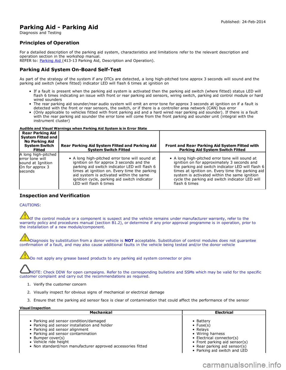
Parking Aid System On-Board Self-Test
As part of the strategy of the system if any DTCs are detected, a long high-pitched tone approx 3 seconds will sound and the
parking aid switch (where fitted) indicator LED will flash 6 times at ignition on
If a fault is present when the parking aid system is activated then the parking aid switch (where fitted) status LED will
flash 6 times indicating an issue with front or rear parking aid sensors, wiring switch, parking aid control module or hard
wired sounders
The rear parking aid sounder/rear audio system will emit an error tone for approx 3 seconds at ignition on if a fault is
detected with the front or rear sensors, the switch, or if there is a controller area network (CAN) bus error
(Only applicable to vehicles fitted with front parking aid and a hard wired rear parking aid sounder). If there is a fault
with the rear parking aid sounder the error tone will come from the front parking aid sounder unit (integral with the
instrument cluster)
Audible and Visual Warnings when Parking Aid System is in Error State
Rear Parking Aid
System Fitted and
No Parking Aid
System Switch
Fitted
Rear Parking Aid System Fitted and Parking Aid System Switch Fitted
Front and Rear Parking Aid System Fitted with Parking Aid System Switch Fitted A long high-pitched
error tone will
sound at Ignition
On for approx 3
seconds
A long high-pitched error tone will sound at
ignition on for approx 3 seconds and the
parking aid switch indicator LED will flash 6
times at ignition on. Every time the parking
aid system is activated within the same
ignition cycle, parking aid switch indicator
LED will flash 6 times
A long high-pitched error tone will sound at
ignition on for approximately 3 seconds and
the parking aid switch indicator LED will flash 6
times at ignition on. Every time the parking aid
system is activated within the same ignition
cycle the parking aid switch indicator LED will
flash 6 times Inspection and Verification
CAUTIONS:
If the control module or a component is suspect and the vehicle remains under manufacturer warranty, refer to the
warranty policy and procedures manual (section B1.2), or determine if any prior approval programme is in operation, prior to
the installation of a new module/component.
Diagnosis by substitution from a donor vehicle is NOT acceptable. Substitution of control modules does not guarantee
confirmation of a fault, and may also cause additional faults in the vehicle being tested and/or the donor vehicle
Do not apply any grease based products to any parking aid system connector or pins
NOTE: Check DDW for open campaigns. Refer to the corresponding bulletins and SSMs which may be valid for the specific
customer complaint and carry out the recommendations as required.
1. Verify the customer concern
2. Visually inspect for obvious signs of mechanical or electrical damage
3. Ensure that the parking aid sensor face is clear of contamination that could affect the performance of the sensor
Visual Inspection
Mechanical Electrical
Parking aid sensor condition/damaged
Parking aid sensor installation and holder
Parking aid sensor alignment
Parking aid sensor contamination
Bumper cover(s)
Vehicle ride height
Non standard/non manufacturer approved accessories fitted
Battery
Fuse(s)
Relays
Wiring harness
Electrical connector(s)
Front parking aid sensor(s)
Rear parking aid sensor(s)
Parking aid switch and LED
Page 1851 of 3039

Mechanical Electrical Parking aid control module
Parking aid sounder
Audio system
4. If an obvious cause for an observed or reported concern is found, correct the cause (if possible) before proceeding to
the next step
5. If the cause is not visually evident, check for diagnostic trouble codes (DTCs) and refer to the DTC index
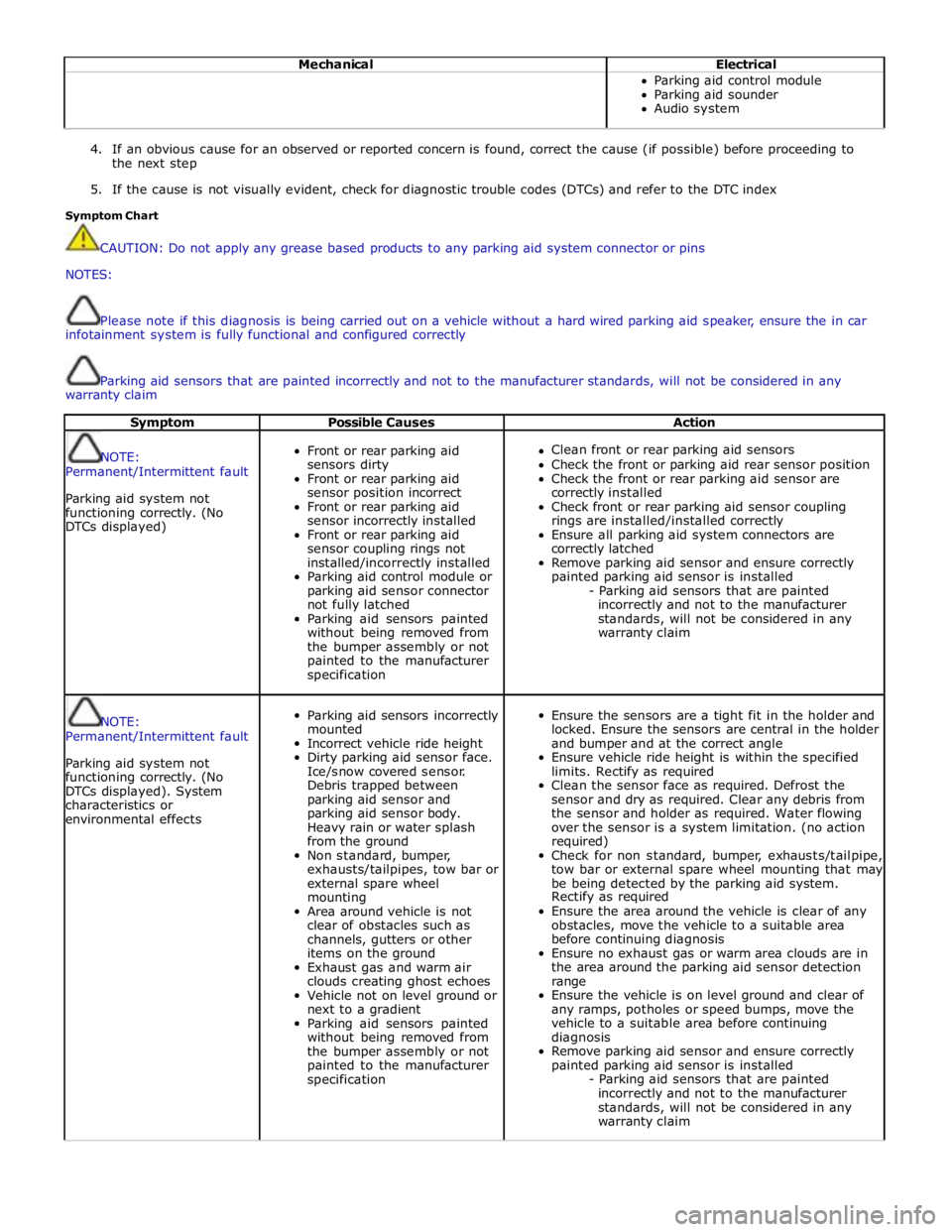
Symptom Chart
CAUTION: Do not apply any grease based products to any parking aid system connector or pins
NOTES:
Please note if this diagnosis is being carried out on a vehicle without a hard wired parking aid speaker, ensure the in car
infotainment system is fully functional and configured correctly
Parking aid sensors that are painted incorrectly and not to the manufacturer standards, will not be considered in any
warranty claim
Symptom Possible Causes Action
NOTE:
Permanent/Intermittent fault
Parking aid system not
functioning correctly. (No
DTCs displayed)
Front or rear parking aid
sensors dirty
Front or rear parking aid
sensor position incorrect
Front or rear parking aid
sensor incorrectly installed
Front or rear parking aid
sensor coupling rings not
installed/incorrectly installed
Parking aid control module or
parking aid sensor connector
not fully latched
Parking aid sensors painted
without being removed from
the bumper assembly or not
painted to the manufacturer
specification
Clean front or rear parking aid sensors
Check the front or parking aid rear sensor position
Check the front or rear parking aid sensor are
correctly installed
Check front or rear parking aid sensor coupling
rings are installed/installed correctly
Ensure all parking aid system connectors are
correctly latched
Remove parking aid sensor and ensure correctly
painted parking aid sensor is installed
- Parking aid sensors that are painted
incorrectly and not to the manufacturer
standards, will not be considered in any
warranty claim
NOTE:
Permanent/Intermittent fault
Parking aid system not
functioning correctly. (No
DTCs displayed). System
characteristics or
environmental effects
Parking aid sensors incorrectly
mounted
Incorrect vehicle ride height
Dirty parking aid sensor face.
Ice/snow covered sensor.
Debris trapped between
parking aid sensor and
parking aid sensor body.
Heavy rain or water splash
from the ground
Non standard, bumper,
exhausts/tailpipes, tow bar or
external spare wheel
mounting
Area around vehicle is not
clear of obstacles such as
channels, gutters or other
items on the ground
Exhaust gas and warm air
clouds creating ghost echoes
Vehicle not on level ground or
next to a gradient
Parking aid sensors painted
without being removed from
the bumper assembly or not
painted to the manufacturer
specification
Ensure the sensors are a tight fit in the holder and
locked. Ensure the sensors are central in the holder
and bumper and at the correct angle
Ensure vehicle ride height is within the specified
limits. Rectify as required
Clean the sensor face as required. Defrost the
sensor and dry as required. Clear any debris from
the sensor and holder as required. Water flowing
over the sensor is a system limitation. (no action
required)
Check for non standard, bumper, exhausts/tailpipe,
tow bar or external spare wheel mounting that may
be being detected by the parking aid system.
Rectify as required
Ensure the area around the vehicle is clear of any
obstacles, move the vehicle to a suitable area
before continuing diagnosis
Ensure no exhaust gas or warm area clouds are in
the area around the parking aid sensor detection
range
Ensure the vehicle is on level ground and clear of
any ramps, potholes or speed bumps, move the
vehicle to a suitable area before continuing
diagnosis
Remove parking aid sensor and ensure correctly
painted parking aid sensor is installed
- Parking aid sensors that are painted
incorrectly and not to the manufacturer
standards, will not be considered in any
warranty claim