2010 JAGUAR XFR height
[x] Cancel search: heightPage 2330 of 3039
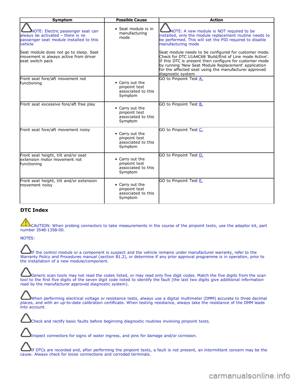
Symptom Possible Cause Action
NOTE: Electric passenger seat can
always be activated – there is no
passenger seat module installed to this
vehicle
Seat module does not go to sleep. Seat
movement is always active from driver
seat switch pack
Seat module is in
manufacturing
mode
NOTE: A new module is NOT required to be
installed, only the module replacement routine needs to
be performed. This will set the PID required to disable
manufacturing mode
Seat module needs to be configured for customer mode.
Check for DTC U1A4C68 'Build/End of Line mode Active'.
If this DTC is present then configure for customer mode
by running 'New Seat Module Replacement' application
for the affected seat using the manufacturer approved diagnostic system Front seat fore/aft movement not
functioning
Carry out the
pinpoint test
associated to this
Symptom GO to Pinpoint Test A. Front seat excessive fore/aft free play
Carry out the
pinpoint test
associated to this
Symptom GO to Pinpoint Test B. Front seat fore/aft movement noisy
Carry out the
pinpoint test
associated to this
Symptom GO to Pinpoint Test C. Front seat height, tilt and/or seat
extension motor movement not
functioning
Carry out the
pinpoint test
associated to this
Symptom GO to Pinpoint Test D. Front seat height, tilt and/or extension
movement noisy
Carry out the
pinpoint test
associated to this
Symptom GO to Pinpoint Test E. DTC Index
CAUTION: When probing connectors to take measurements in the course of the pinpoint tests, use the adaptor kit, part
number 3548-1358-00.
NOTES:
If the control module or a component is suspect and the vehicle remains under manufacturer warranty, refer to the
Warranty Policy and Procedures manual (section B1.2), or determine if any prior approval programme is in operation, prior to
the installation of a new module/component.
Generic scan tools may not read the codes listed, or may read only five digit codes. Match the five digits from the scan
tool to the first five digits of the seven digit code listed to identify the fault (the last two digits give additional information
read by the manufacturer approved diagnostic system).
When performing electrical voltage or resistance tests, always use a digital multimeter (DMM) accurate to three decimal
places, and with an up-to-date calibration certificate. When testing resistance, always take the resistance of the DMM leads
into account.
Check and rectify basic faults before beginning diagnostic routines involving pinpoint tests.
Inspect connectors for signs of water ingress, and pins for damage and/or corrosion.
If DTCs are recorded and, after performing the pinpoint tests, a fault is not present, an intermittent concern may be the
cause. Always check for loose connections and corroded terminals.
Page 2331 of 3039

Driver Seat Module
DTC Description Possible Cause Action B105F11
Seat Cushion
Extension Motor
Output
Driver seat cushion extension
motor circuit - short to ground Carry out any pinpoint tests associated with this DTC
using the manufacturer approved diagnostic system.
Refer to the electrical circuit diagrams and check driver
seat cushion extension motor circuit for short to ground B105F15
Seat Cushion
Extension Motor
Output
Driver seat cushion extension
motor circuit - short to power,
open circuit Carry out any pinpoint tests associated with this DTC
using the manufacturer approved diagnostic system.
Refer to the electrical circuit diagrams and check driver
seat cushion extension motor circuit for short to power, open circuit B106011
Seat Headrest Motor
Output
Driver seat headrest motor circuit
- short to ground Carry out any pinpoint tests associated with this DTC
using the manufacturer approved diagnostic system.
Refer to the electrical circuit diagrams and check driver
seat headrest motor circuit for short to ground B106015
Seat Headrest Motor
Output
Driver seat headrest motor circuit
- short to power, open circuit Carry out any pinpoint tests associated with this DTC
using the manufacturer approved diagnostic system.
Refer to the electrical circuit diagrams and check driver
seat headrest motor circuit for short to power, open
circuit B106331
Seat Cushion
Extension Motor
Speed/Position
Sensor
Harness/connector problem
No signal from sensor
Sensor/motor malfunction
Check the seat wiring harness/connectors for
security/integrity
Refer to the electrical circuit diagrams and check
the seat cushion motor sensor circuit. Repair
circuit as required. Clear DTC and retest B106431
Seat Headrest Motor
Speed/Position
Sensor
Harness/connector problem
No signal from sensor
Sensor/motor malfunction
Check the seat wiring harness/connectors for
security/integrity
Refer to the electrical circuit diagrams and check
the seat headrest motor sensor circuit. Repair
circuit as required. Clear DTC and retest B106524
Cushion extend
switch
Signal stuck high Check for a stuck switch. Refer to the electrical circuit
diagrams and check driver seat switch pack to seat
module LIN circuit for short, open circuit and cushion
extend circuit for short to ground B106624
Cushion retract
switch
Signal stuck high Check for a stuck switch. Refer to the electrical circuit
diagrams and check driver seat switch pack to seat
module LIN circuit for short, open circuit and cushion
retract circuit for short to ground B106D24 Headrest up switch
Signal stuck high Check for a stuck switch. Refer to the electrical circuit
diagrams and check driver seat switch pack to seat
module LIN circuit for short, open circuit and headrest up circuit for short to ground B106E24
Headrest down
switch
Signal stuck high Check for a stuck switch. Refer to the electrical circuit
diagrams and check driver seat switch pack to seat
module LIN circuit for short, open circuit and headrest
down circuit for short to ground B1A9883 LIN Bus Circuit #1
Value of signal protection
calculation incorrect Check LIN network for interference/EMC related issues B1A9886 LIN Bus Circuit #1
LIN bus Header error Carry out any pinpoint tests associated with this DTC
using the manufacturer approved diagnostic system.
Check LIN network for interference/EMC related issues B1A9887 LIN Bus Circuit #1
Slave node communication
missing. LIN bus circuit - short to
ground, power, open circuit (ECU
Types 7 & 8) Refer to electrical circuit diagrams and test LIN Bus
between seat switch pack and control module for short
to ground, power, open circuit, check power and ground
supplies to switch pack B1A9888 LIN Bus Circuit #1
Bus off Carry out any pinpoint tests associated with this DTC
using the manufacturer approved diagnostic system.
Refer to electrical circuit diagrams and test LIN Bus
between seat switch pack and control module for short
to ground or power B1B8611
Seat Height Motor
Relay
Driver seat parallel height motor
circuit - short to ground Carry out any pinpoint tests associated with this DTC
using the manufacturer approved diagnostic system.
Refer to the electrical circuit diagrams and check driver
seat parallel height motor circuit for short to ground B1B8615
Seat Height Motor
Relay
Driver seat parallel height motor
circuit - short to power, open
circuit Carry out any pinpoint tests associated with this DTC
using the manufacturer approved diagnostic system.
Refer to the electrical circuit diagrams and check driver
seat parallel height motor circuit for short to power, open circuit
Page 2332 of 3039

DTC Description Possible Cause Action B1B8731
Seat Height Motor
Speed/Position
Sensor
Harness/connector problem
No signal from sensor
Sensor/motor malfunction
Check the seat wiring harness/connectors for
security/integrity
Refer to the electrical circuit diagrams and check
the seat height motor sensor circuit. Repair
circuit as required. Clear DTC and retest B1B8811
Seat Slide Motor
Relay
Driver seat slide motor circuit -
short to ground Carry out any pinpoint tests associated with this DTC
using the manufacturer approved diagnostic system.
Refer to the electrical circuit diagrams and check driver
seat slide motor circuit for short to ground B1B8815
Seat Slide Motor
Relay
Driver seat slide motor circuit -
short to power, open circuit Carry out any pinpoint tests associated with this DTC
using the manufacturer approved diagnostic system.
Refer to the electrical circuit diagrams and check driver
seat slide motor circuit for short to power, open circuit B1B8931
Seat Slide Motor
Speed/Position
Sensor
Harness/connector problem
No signal from sensor
Sensor/motor malfunction
Check the seat wiring harness/connectors for
security/integrity
Refer to the electrical circuit diagrams and check the seat slide motor speed sensor circuit. Repair circuit as required. Clear DTC and retest B1B9011
Seat Tilt Motor
Relay
Driver seat tilt motor circuit -
short to ground Carry out any pinpoint tests associated with this DTC
using the manufacturer approved diagnostic system.
Refer to the electrical circuit diagrams and check driver
seat tilt motor circuit for short to ground B1B9015
Seat Tilt Motor
Relay
Driver seat tilt motor circuit -
short to power, open circuit Carry out any pinpoint tests associated with this DTC
using the manufacturer approved diagnostic system.
Refer to the electrical circuit diagrams and check driver
seat tilt motor circuit for short to power, open circuit B1B9131
Seat Tilt Motor
Speed/Position
Sensor
Harness/connector problem
No signal from sensor
Sensor/motor malfunction
Check the seat wiring harness/connectors for
security/integrity
Refer to the electrical circuit diagrams and check
the seat tilt motor speed sensor circuit. Repair
circuit as required. Clear DTC and retest B1B9211
Seat Recline Motor
Relay
Driver seat recline motor circuit -
short to ground Carry out any pinpoint tests associated with this DTC
using the manufacturer approved diagnostic system.
Refer to the electrical circuit diagrams and check driver
seat recline motor circuit for short to ground B1B9215
Seat Recline Motor
Relay
Driver seat recline motor circuit -
short to power, open circuit Carry out any pinpoint tests associated with this DTC
using the manufacturer approved diagnostic system.
Refer to the electrical circuit diagrams and check driver
seat recline motor circuit for short to power, open
circuit B1B9331
Seat Recline Motor
Speed/Position
Sensor
Harness/connector problem
No signal from sensor
Sensor/motor malfunction
Check the seat wiring harness/connectors for
security/integrity
Refer to the electrical circuit diagrams and check
the seat recline motor speed sensor circuit.
Repair circuit as required. Clear DTC and retest B1B9424
Seat Height Up
Switch
Signal stuck high Check for a stuck switch. Refer to the electrical circuit
diagrams and check driver seat switch pack to seat
module LIN circuit for short, open circuit and seat height up circuit for short to ground B1B9524
Seat Height Down
Switch
Signal stuck high Check for a stuck switch. Refer to the electrical circuit
diagrams and check driver seat switch pack to seat
module LIN circuit for short, open circuit and seat height down circuit for short to ground B1B9624
Seat Slide Forward
Switch
Signal stuck high Check for a stuck switch. Refer to the electrical circuit
diagrams and check driver seat switch pack to seat
module LIN circuit for short, open circuit and seat slide
forward circuit for short to ground B1B9724
Seat Slide Backward
Switch
Signal stuck high Check for a stuck switch. Refer to the electrical circuit
diagrams and check driver seat switch pack to seat
module LIN circuit for short, open circuit and seat slide
backward circuit for short to ground B1B9824 Seat Tilt Up Switch
Signal stuck high Check for a stuck switch. Refer to the electrical circuit
diagrams and check driver seat switch pack to seat
module LIN circuit for short, open circuit and seat tilt up circuit for short to ground B1B9924
Seat Tilt Down
Switch
Signal stuck high Check for a stuck switch. Refer to the electrical circuit
diagrams and check driver seat switch pack to seat
module LIN circuit for short, open circuit and seat tilt
down circuit for short to ground
Page 2335 of 3039
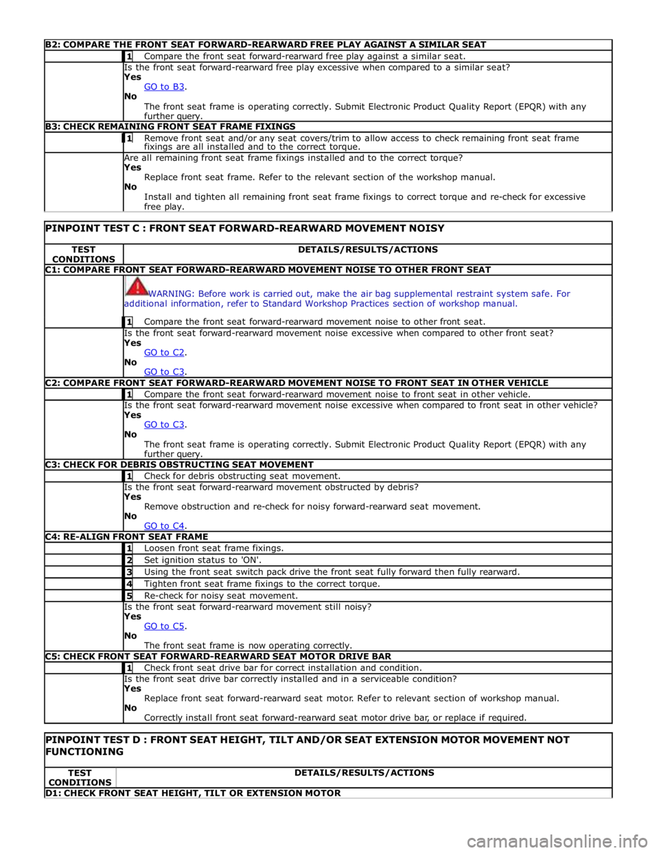
B2: COMPARE THE FRONT SEAT FORWARD-REARWARD FREE PLAY AGAINST A SIMILAR SEAT 1 Compare the front seat forward-rearward free play against a similar seat. Is the front seat forward-rearward free play excessive when compared to a similar seat?
Yes
GO to B3. No
The front seat frame is operating correctly. Submit Electronic Product Quality Report (EPQR) with any
further query. B3: CHECK REMAINING FRONT SEAT FRAME FIXINGS 1 Remove front seat and/or any seat covers/trim to allow access to check remaining front seat frame fixings are all installed and to the correct torque. Are all remaining front seat frame fixings installed and to the correct torque?
Yes
Replace front seat frame. Refer to the relevant section of the workshop manual.
No
Install and tighten all remaining front seat frame fixings to correct torque and re-check for excessive
free play.
PINPOINT TEST C : FRONT SEAT FORWARD-REARWARD MOVEMENT NOISY TEST
CONDITIONS DETAILS/RESULTS/ACTIONS C1: COMPARE FRONT SEAT FORWARD-REARWARD MOVEMENT NOISE TO OTHER FRONT SEAT
WARNING: Before work is carried out, make the air bag supplemental restraint system safe. For
additional information, refer to Standard Workshop Practices section of workshop manual. 1 Compare the front seat forward-rearward movement noise to other front seat. Is the front seat forward-rearward movement noise excessive when compared to other front seat?
Yes
GO to C2. No
GO to C3. C2: COMPARE FRONT SEAT FORWARD-REARWARD MOVEMENT NOISE TO FRONT SEAT IN OTHER VEHICLE 1 Compare the front seat forward-rearward movement noise to front seat in other vehicle. Is the front seat forward-rearward movement noise excessive when compared to front seat in other vehicle?
Yes
GO to C3. No
The front seat frame is operating correctly. Submit Electronic Product Quality Report (EPQR) with any
further query. C3: CHECK FOR DEBRIS OBSTRUCTING SEAT MOVEMENT 1 Check for debris obstructing seat movement. Is the front seat forward-rearward movement obstructed by debris?
Yes
Remove obstruction and re-check for noisy forward-rearward seat movement.
No
GO to C4. C4: RE-ALIGN FRONT SEAT FRAME 1 Loosen front seat frame fixings. 2 Set ignition status to 'ON'. 3 Using the front seat switch pack drive the front seat fully forward then fully rearward. 4 Tighten front seat frame fixings to the correct torque. 5 Re-check for noisy seat movement. Is the front seat forward-rearward movement still noisy?
Yes
GO to C5. No
The front seat frame is now operating correctly. C5: CHECK FRONT SEAT FORWARD-REARWARD SEAT MOTOR DRIVE BAR 1 Check front seat drive bar for correct installation and condition. Is the front seat drive bar correctly installed and in a serviceable condition?
Yes
Replace front seat forward-rearward seat motor. Refer to relevant section of workshop manual.
No
Correctly install front seat forward-rearward seat motor drive bar, or replace if required.
PINPOINT TEST D : FRONT SEAT HEIGHT, TILT AND/OR SEAT EXTENSION MOTOR MOVEMENT NOT FUNCTIONING TEST
CONDITIONS DETAILS/RESULTS/ACTIONS D1: CHECK FRONT SEAT HEIGHT, TILT OR EXTENSION MOTOR
Page 2336 of 3039
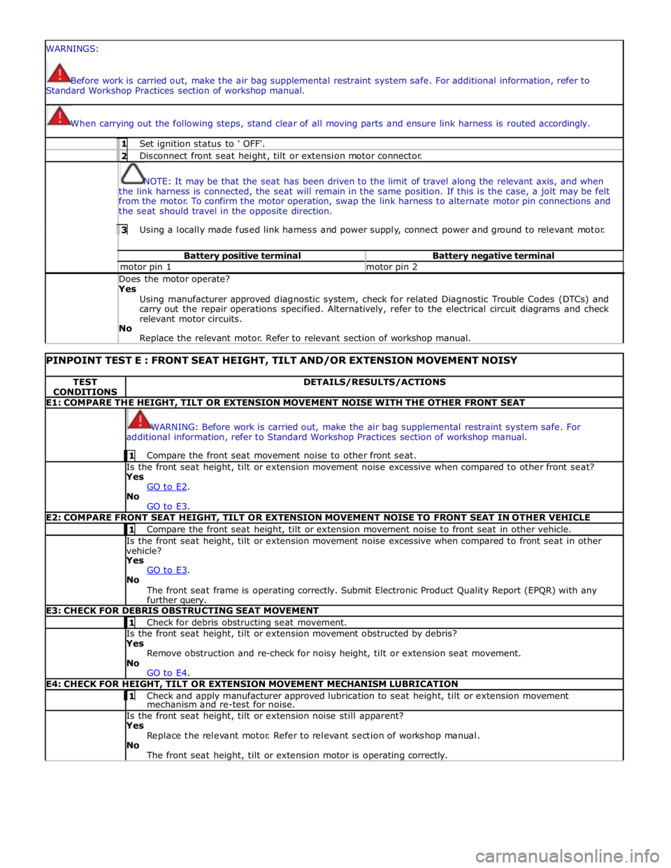
WARNINGS:
Before work is carried out, make the air bag supplemental restraint system safe. For additional information, refer to
Standard Workshop Practices section of workshop manual.
When carrying out the following steps, stand clear of all moving parts and ensure link harness is routed accordingly. 1 Set ignition status to ' OFF'. 2 Disconnect front seat height, tilt or extension motor connector.
NOTE: It may be that the seat has been driven to the limit of travel along the relevant axis, and when
the link harness is connected, the seat will remain in the same position. If this is the case, a jolt may be felt
from the motor. To confirm the motor operation, swap the link harness to alternate motor pin connections and
the seat should travel in the opposite direction. 3 Using a locally made fused link harness and power supply, connect power and ground to relevant motor. Battery positive terminal Battery negative terminal motor pin 1 motor pin 2 Does the motor operate? Yes
Using manufacturer approved diagnostic system, check for related Diagnostic Trouble Codes (DTCs) and
carry out the repair operations specified. Alternatively, refer to the electrical circuit diagrams and check
relevant motor circuits.
No
Replace the relevant motor. Refer to relevant section of workshop manual.
PINPOINT TEST E : FRONT SEAT HEIGHT, TILT AND/OR EXTENSION MOVEMENT NOISY TEST
CONDITIONS DETAILS/RESULTS/ACTIONS E1: COMPARE THE HEIGHT, TILT OR EXTENSION MOVEMENT NOISE WITH THE OTHER FRONT SEAT
WARNING: Before work is carried out, make the air bag supplemental restraint system safe. For
additional information, refer to Standard Workshop Practices section of workshop manual. 1 Compare the front seat movement noise to other front seat. Is the front seat height, tilt or extension movement noise excessive when compared to other front seat?
Yes
GO to E2. No
GO to E3. E2: COMPARE FRONT SEAT HEIGHT, TILT OR EXTENSION MOVEMENT NOISE TO FRONT SEAT IN OTHER VEHICLE 1 Compare the front seat height, tilt or extension movement noise to front seat in other vehicle. Is the front seat height, tilt or extension movement noise excessive when compared to front seat in other
vehicle?
Yes
GO to E3. No
The front seat frame is operating correctly. Submit Electronic Product Quality Report (EPQR) with any
further query. E3: CHECK FOR DEBRIS OBSTRUCTING SEAT MOVEMENT 1 Check for debris obstructing seat movement. Is the front seat height, tilt or extension movement obstructed by debris?
Yes
Remove obstruction and re-check for noisy height, tilt or extension seat movement.
No
GO to E4. E4: CHECK FOR HEIGHT, TILT OR EXTENSION MOVEMENT MECHANISM LUBRICATION 1 Check and apply manufacturer approved lubrication to seat height, tilt or extension movement mechanism and re-test for noise. Is the front seat height, tilt or extension noise still apparent?
Yes
Replace the relevant motor. Refer to relevant section of workshop manual.
No
The front seat height, tilt or extension motor is operating correctly.
Page 2385 of 3039
Seating - Front Seat Height Adjustment Motor
Removal and Installation
Removal
NOTE: Removal steps in this procedure may contain installation details. Published: 11-May-2011
1. Make the air bag supplemental restraint system (SRS) safe.
Refer to: Standard Workshop Practices (100-00 General Information, Description and Operation).
2. Disconnect the battery ground cable.
Refer to: Battery Disconnect and Connect (414-01 Battery, Mounting and Cables, General Procedures).
3. Remove the front seat.
Refer to: Front Seat (501-10 Seating, Removal and Installation).
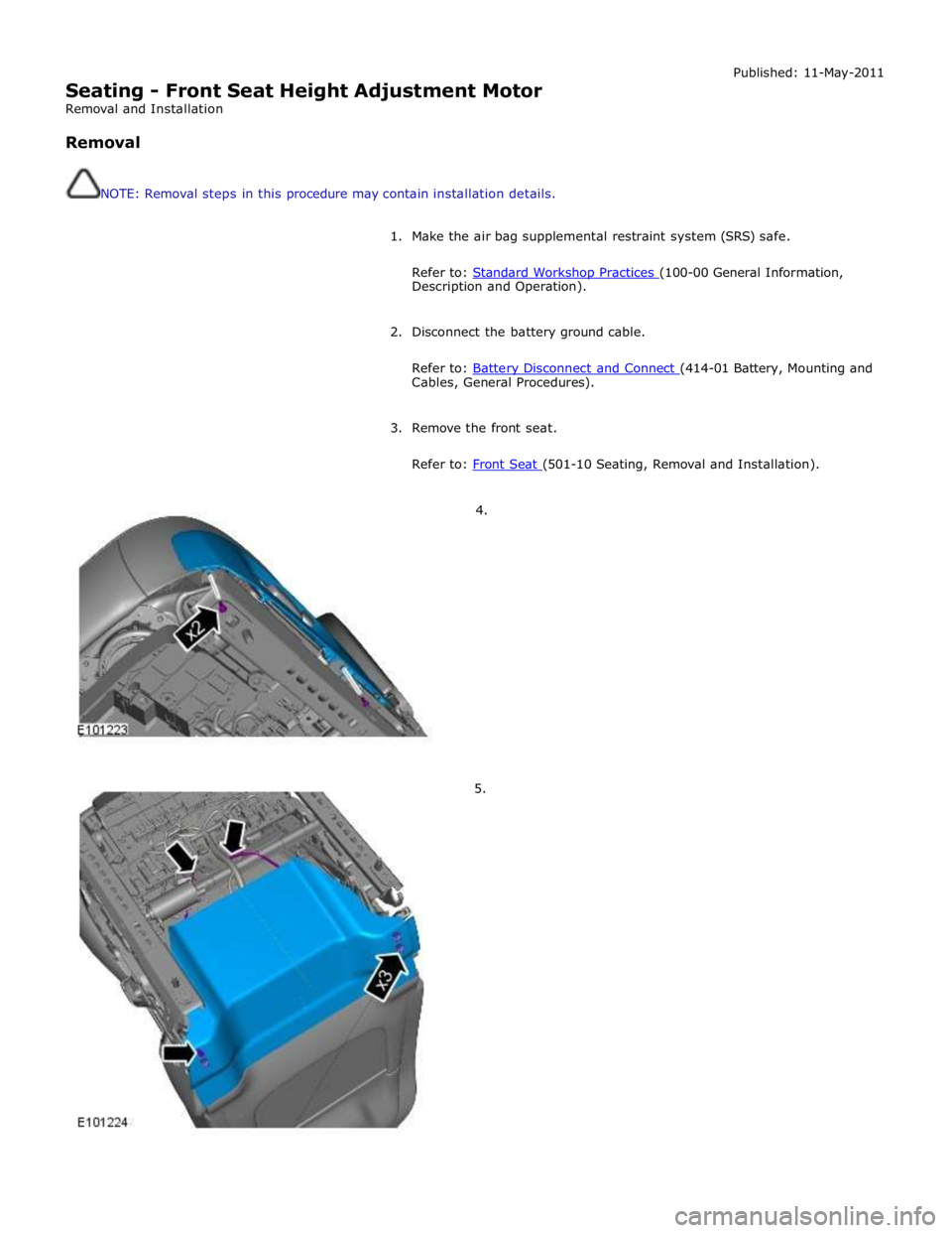
4.
5.
Page 2590 of 3039

Front safety belt retractor to seat track retaining bolt 40 30 - Front safety belt retractor retaining bolt 40 30 - Front safety belt D loop retaining bolt 40 30 - Front safety belt buckle retaining bolt 40 30 - Front safety belt shoulder height adjuster retaining bolts 25 18 - Rear centre safety belt retractor retaining bolts 40 30 - Rear safety belt long end retaining bolts 40 30 - Rear safety belt D loop retaining bolt 40 30 - Rear safety belt long end retaining bolt 40 30 - Rear safety belt buckle retaining bolts 40 30 -
Page 2599 of 3039
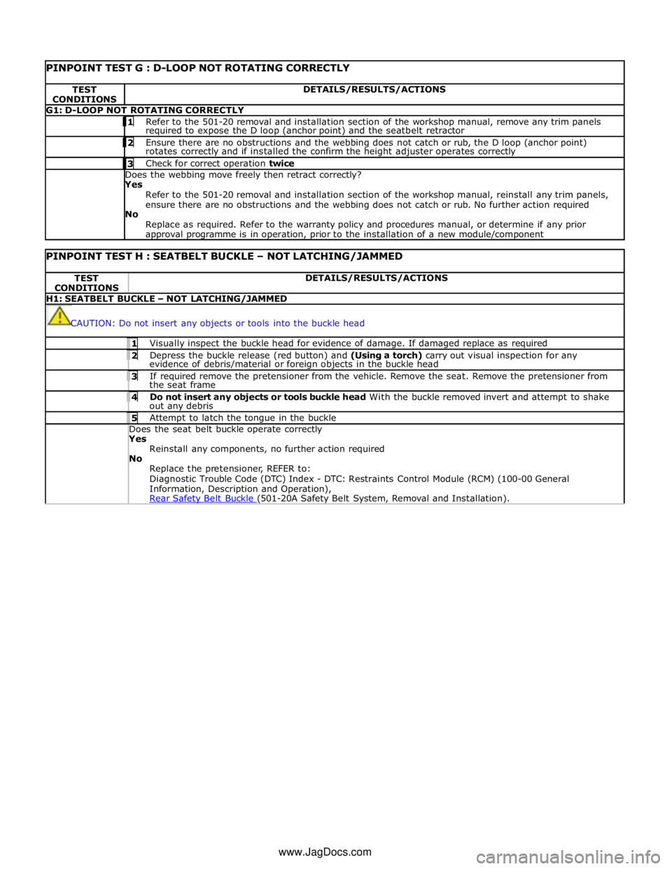
PINPOINT TEST G : D-LOOP NOT ROTATING CORRECTLY TEST
CONDITIONS DETAILS/RESULTS/ACTIONS G1: D-LOOP NOT ROTATING CORRECTLY 1 Refer to the 501-20 removal and installation section of the workshop manual, remove any trim panels required to expose the D loop (anchor point) and the seatbelt retractor 2 Ensure there are no obstructions and the webbing does not catch or rub, the D loop (anchor point) rotates correctly and if installed the confirm the height adjuster operates correctly 3 Check for correct operation twice Does the webbing move freely then retract correctly? Yes
Refer to the 501-20 removal and installation section of the workshop manual, reinstall any trim panels,
ensure there are no obstructions and the webbing does not catch or rub. No further action required
No
Replace as required. Refer to the warranty policy and procedures manual, or determine if any prior approval programme is in operation, prior to the installation of a new module/component
PINPOINT TEST H : SEATBELT BUCKLE – NOT LATCHING/JAMMED TEST
CONDITIONS DETAILS/RESULTS/ACTIONS H1: SEATBELT BUCKLE – NOT LATCHING/JAMMED
CAUTION: Do not insert any objects or tools into the buckle head 1 Visually inspect the buckle head for evidence of damage. If damaged replace as required 2 Depress the buckle release (red button) and (Using a torch) carry out visual inspection for any evidence of debris/material or foreign objects in the buckle head 3 If required remove the pretensioner from the vehicle. Remove the seat. Remove the pretensioner from the seat frame 4 Do not insert any objects or tools buckle head With the buckle removed invert and attempt to shake out any debris 5 Attempt to latch the tongue in the buckle Does the seat belt buckle operate correctly Yes
Reinstall any components, no further action required
No
Replace the pretensioner, REFER to:
Diagnostic Trouble Code (DTC) Index - DTC: Restraints Control Module (RCM) (100-00 General
Information, Description and Operation),
Rear Safety Belt Buckle (501-20A Safety Belt System, Removal and Installation). www.JagDocs.com