2010 JAGUAR XFR height
[x] Cancel search: heightPage 1854 of 3039
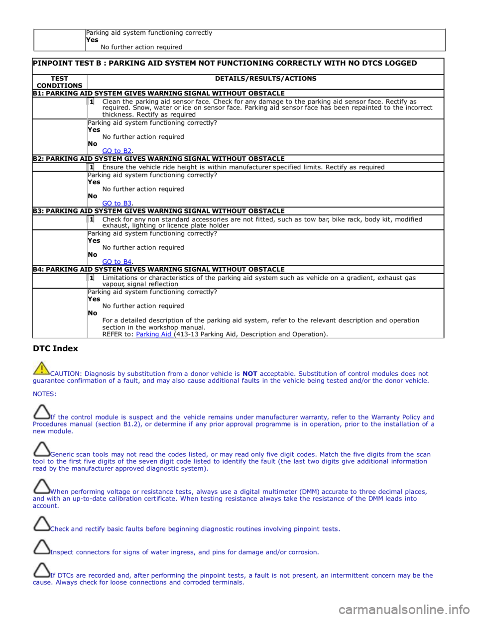
PINPOINT TEST B : PARKING AID SYSTEM NOT FUNCTIONING CORRECTLY WITH NO DTCS LOGGED TEST
CONDITIONS DETAILS/RESULTS/ACTIONS B1: PARKING AID SYSTEM GIVES WARNING SIGNAL WITHOUT OBSTACLE 1 Clean the parking aid sensor face. Check for any damage to the parking aid sensor face. Rectify as required. Snow, water or ice on sensor face. Parking aid sensor face has been repainted to the incorrect
thickness. Rectify as required Parking aid system functioning correctly? Yes
No further action required
No
GO to B2. B2: PARKING AID SYSTEM GIVES WARNING SIGNAL WITHOUT OBSTACLE 1 Ensure the vehicle ride height is within manufacturer specified limits. Rectify as required Parking aid system functioning correctly? Yes
No further action required
No
GO to B3. B3: PARKING AID SYSTEM GIVES WARNING SIGNAL WITHOUT OBSTACLE 1 Check for any non standard accessories are not fitted, such as tow bar, bike rack, body kit, modified exhaust, lighting or licence plate holder Parking aid system functioning correctly? Yes
No further action required
No
GO to B4. B4: PARKING AID SYSTEM GIVES WARNING SIGNAL WITHOUT OBSTACLE 1 Limitations or characteristics of the parking aid system such as vehicle on a gradient, exhaust gas vapour, signal reflection Parking aid system functioning correctly? Yes
No further action required
No
For a detailed description of the parking aid system, refer to the relevant description and operation
section in the workshop manual.
REFER to: Parking Aid (413-13 Parking Aid, Description and Operation). DTC Index
CAUTION: Diagnosis by substitution from a donor vehicle is NOT acceptable. Substitution of control modules does not
guarantee confirmation of a fault, and may also cause additional faults in the vehicle being tested and/or the donor vehicle.
NOTES:
If the control module is suspect and the vehicle remains under manufacturer warranty, refer to the Warranty Policy and
Procedures manual (section B1.2), or determine if any prior approval programme is in operation, prior to the installation of a
new module.
Generic scan tools may not read the codes listed, or may read only five digit codes. Match the five digits from the scan
tool to the first five digits of the seven digit code listed to identify the fault (the last two digits give additional information
read by the manufacturer approved diagnostic system).
When performing voltage or resistance tests, always use a digital multimeter (DMM) accurate to three decimal places,
and with an up-to-date calibration certificate. When testing resistance always take the resistance of the DMM leads into
account.
Check and rectify basic faults before beginning diagnostic routines involving pinpoint tests.
Inspect connectors for signs of water ingress, and pins for damage and/or corrosion.
If DTCs are recorded and, after performing the pinpoint tests, a fault is not present, an intermittent concern may be the
cause. Always check for loose connections and corroded terminals. Parking aid system functioning correctly
Yes
No further action required
Page 1975 of 3039

7 Microphone 8 Navigation computer 9 VICS (vehicle information and communication system) beacon antenna - Japan only 10 Roof pod antenna module (GPS (global positioning system) antenna) 11 Diversity antenna module (VICS/TMC antenna) 12 ICP (integrated control panel) 13 ICM (information control module) 14 Clock spring 15 Instrument cluster
Authoring Template System Operation
INTRODUCTION TO THE GLOBAL POSITIONING SYSTEM
The system used to calculate the current position of the vehicle is called the GPS. The system utilizes satellites which are owned by the United States Department of Defense. A total of 24 satellites circular orbit the earth every 12 hours at a height
of 20,000 km (12500 miles), and between 5 and 11 of these satellites can be seen from a single point at any given time. The
orbits are tilted to the earth's equator by 55 degrees to ensure coverage of polar regions. Each satellite transmits radio signals
to provide information about the satellite position i.e. latitude, longitude, altitude, almanac data and an accurate time signal
generated by an on-board atomic clock. Each satellite contains four atomic clocks.
The vehicle needs to receive data from at least four different satellites to give a three dimensional fix on its current position.
As the vehicle moves, this information is continually being updated. The computer determines which satellites are 'visible' to
the system and their current position and relationship to each other. Using this information the computer can account for
positional deviations of the satellites and compensate to enhance the accuracy of the navigation system.
www.JagDocs.com
Page 2020 of 3039
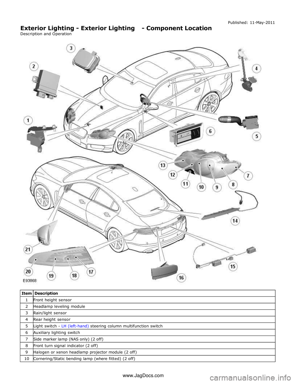
1 Front height sensor 2 Headlamp leveling module 3 Rain/light sensor 4 Rear height sensor 5 Light switch - LH (left-hand) steering column multifunction switch 6 Auxiliary lighting switch 7 Side marker lamp (NAS only) (2 off) 8 Front turn signal indicator (2 off) 9 Halogen or xenon headlamp projector module (2 off) 10 Cornering/Static bending lamp (where fitted) (2 off) www.JagDocs.com
Page 2022 of 3039

The lighting system has an 'auto' lights function which is controlled by the CJB on receipt of signals from the rain/light sensor located at the top of the windscreen. The exterior lights are turned on or off in response to ambient light signals from the
rain/light sensor on a LIN (local interconnect network) bus connection to the CJB . The auto lights can also be activated when the windshield wipers are activated by signals from the rain sensor, which is located at the top of the windshield or when the
driver activates the wipers in the fast wipe position.
Two levels of headlamp specification are available; halogen or xenon. In certain markets the headlamps feature a cornering
lamp or a static bending lamp which illuminates the area at the side of the vehicle when turning into driveways for example.
North American Specification (NAS) vehicles have a side marker lamp installed in the headlamp assembly. Replacement of any
of the headlamp bulbs requires removal of the headlamp assembly.
The tail lamp comprises two separate lamp assemblies. The turn signal indicator, side and stop lamps and reverse lamps are
located in each rear fender tail lamp assembly. The rear fog lamps are located in separate units attached to the luggage
compartment lid. A side marker lamp is fitted to the rear fender tail lamp assembly and is fitted in all markets.
Two systems of headlamp leveling are available; manual leveling which is only available on halogen headlamps and static
dynamic leveling which is available on xenon headlamps. The manual system uses a thumbwheel rheostat to adjust the
vertical alignment of the headlamps to compensate for differing vehicle loading. The static dynamic system uses height
sensors fitted to the front and rear suspension and a headlamp leveling module which periodically monitors the vehicle
attitude and adjusts the headlamp vertical alignment accordingly.
Page 2024 of 3039
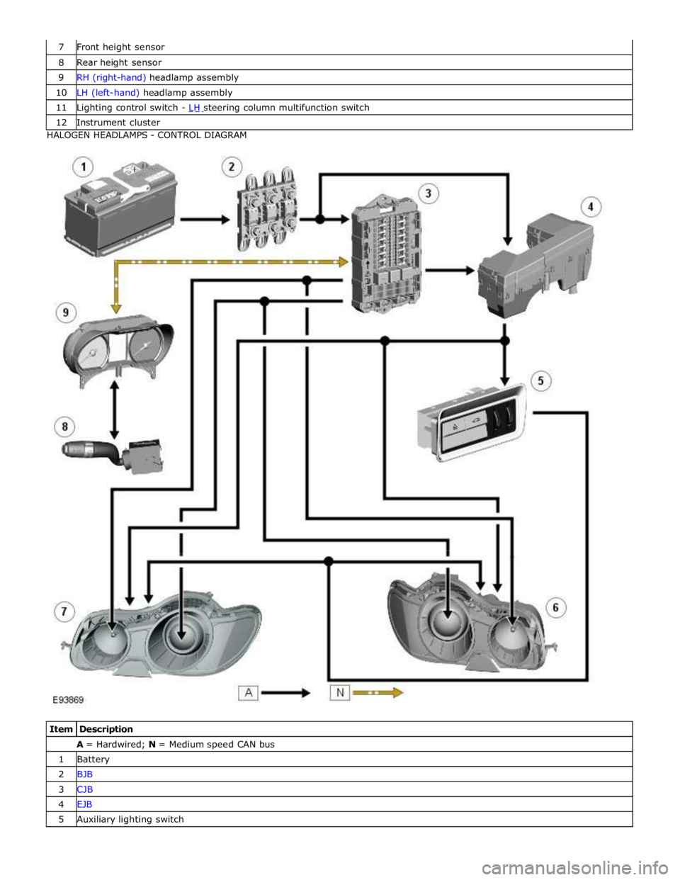
8 Rear height sensor 9 RH (right-hand) headlamp assembly 10 LH (left-hand) headlamp assembly 11 Lighting control switch - LH steering column multifunction switch 12 Instrument cluster HALOGEN HEADLAMPS - CONTROL DIAGRAM
Item Description A = Hardwired; N = Medium speed CAN bus 1 Battery 2 BJB 3 CJB 4 EJB 5 Auxiliary lighting switch
Page 2028 of 3039
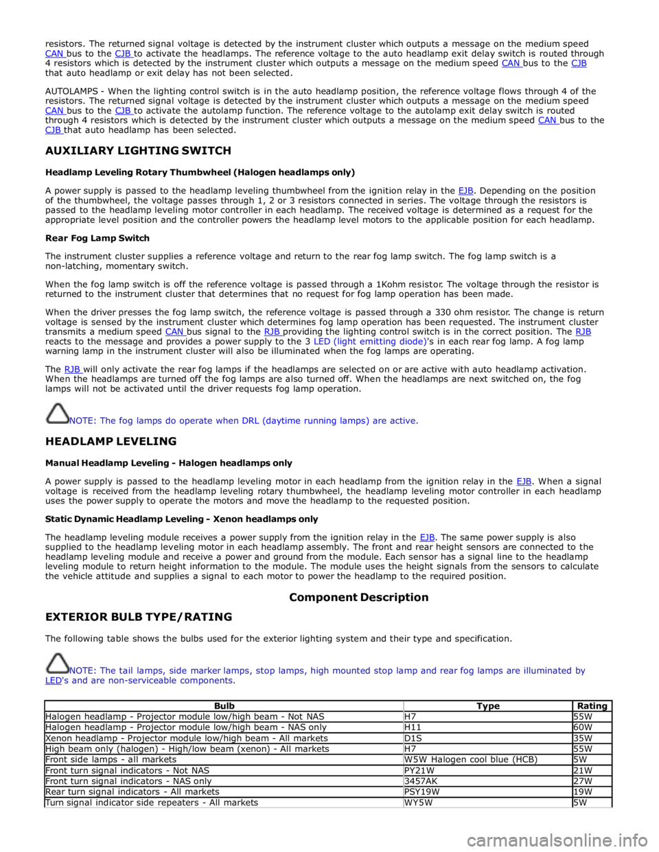
resistors. The returned signal voltage is detected by the instrument cluster which outputs a message on the medium speed
CAN bus to the CJB to activate the headlamps. The reference voltage to the auto headlamp exit delay switch is routed through 4 resistors which is detected by the instrument cluster which outputs a message on the medium speed CAN bus to the CJB that auto headlamp or exit delay has not been selected.
AUTOLAMPS - When the lighting control switch is in the auto headlamp position, the reference voltage flows through 4 of the
resistors. The returned signal voltage is detected by the instrument cluster which outputs a message on the medium speed
CAN bus to the CJB to activate the autolamp function. The reference voltage to the autolamp exit delay switch is routed through 4 resistors which is detected by the instrument cluster which outputs a message on the medium speed CAN bus to the CJB that auto headlamp has been selected.
AUXILIARY LIGHTING SWITCH
Headlamp Leveling Rotary Thumbwheel (Halogen headlamps only)
A power supply is passed to the headlamp leveling thumbwheel from the ignition relay in the EJB. Depending on the position of the thumbwheel, the voltage passes through 1, 2 or 3 resistors connected in series. The voltage through the resistors is
passed to the headlamp leveling motor controller in each headlamp. The received voltage is determined as a request for the
appropriate level position and the controller powers the headlamp level motors to the applicable position for each headlamp.
Rear Fog Lamp Switch
The instrument cluster supplies a reference voltage and return to the rear fog lamp switch. The fog lamp switch is a
non-latching, momentary switch.
When the fog lamp switch is off the reference voltage is passed through a 1Kohm resistor. The voltage through the resistor is
returned to the instrument cluster that determines that no request for fog lamp operation has been made.
When the driver presses the fog lamp switch, the reference voltage is passed through a 330 ohm resistor. The change is return
voltage is sensed by the instrument cluster which determines fog lamp operation has been requested. The instrument cluster
transmits a medium speed CAN bus signal to the RJB providing the lighting control switch is in the correct position. The RJB reacts to the message and provides a power supply to the 3 LED (light emitting diode)'s in each rear fog lamp. A fog lamp
warning lamp in the instrument cluster will also be illuminated when the fog lamps are operating.
The RJB will only activate the rear fog lamps if the headlamps are selected on or are active with auto headlamp activation. When the headlamps are turned off the fog lamps are also turned off. When the headlamps are next switched on, the fog
lamps will not be activated until the driver requests fog lamp operation.
NOTE: The fog lamps do operate when DRL (daytime running lamps) are active.
HEADLAMP LEVELING
Manual Headlamp Leveling - Halogen headlamps only
A power supply is passed to the headlamp leveling motor in each headlamp from the ignition relay in the EJB. When a signal voltage is received from the headlamp leveling rotary thumbwheel, the headlamp leveling motor controller in each headlamp
uses the power supply to operate the motors and move the headlamp to the requested position.
Static Dynamic Headlamp Leveling - Xenon headlamps only
The headlamp leveling module receives a power supply from the ignition relay in the EJB. The same power supply is also supplied to the headlamp leveling motor in each headlamp assembly. The front and rear height sensors are connected to the
headlamp leveling module and receive a power and ground from the module. Each sensor has a signal line to the headlamp
leveling module to return height information to the module. The module uses the height signals from the sensors to calculate
the vehicle attitude and supplies a signal to each motor to power the headlamp to the required position.
EXTERIOR BULB TYPE/RATING Component Description
The following table shows the bulbs used for the exterior lighting system and their type and specification.
NOTE: The tail lamps, side marker lamps, stop lamps, high mounted stop lamp and rear fog lamps are illuminated by
LED's and are non-serviceable components.
Bulb Type Rating Halogen headlamp - Projector module low/high beam - Not NAS H7 55W Halogen headlamp - Projector module low/high beam - NAS only H11 60W Xenon headlamp - Projector module low/high beam - All markets D1S 35W High beam only (halogen) - High/low beam (xenon) - All markets H7 55W Front side lamps - all markets W5W Halogen cool blue (HCB) 5W Front turn signal indicators - Not NAS PY21W 21W Front turn signal indicators - NAS only 3457AK 27W Rear turn signal indicators - All markets PSY19W 19W Turn signal indicator side repeaters - All markets WY5W 5W
Page 2034 of 3039

dependant on a particular ignition mode status. The side lamps will also be illuminated when the lighting control switch is in
the AUTO position and a 'lights on' signal is received by the CJB from the rain/light sensor Side Marker Lamps (NAS only)
The side marker lamp is located in the outer part of the headlamp assembly. The side marker lamp uses a W5W wedge fitting
bulb. The bulb is fitted into a holder which connects with contacts in the headlamp housing. The holder is fitted into an
aperture which connects with contacts in the headlamp housing. The side marker lamp is active at all times when the side
lamps are active.
AUTOMATIC HEADLAMP OPERATION
The automatic headlamp function is a driver assistance system. The driver can override the system operation by selection of
side lamp or headlamp on if the ambient light conditions require front and rear lighting to be active. The automatic headlamp
system uses a light sensor and the CJB, which are connected via a LIN (local interconnect network) bus to control the headlamp functionality. The light sensor is incorporated in the rain/light sensor located on the inside of the windshield, below
the rear view mirror. The wiper system also uses the rain/light sensor for automatic wiper operation.
The light sensor measures the ambient light around the vehicle in a vertical direction and also the angular light level from the
front of the vehicle. The rain/light sensor uses vehicle speed signals, wiper switch position and the park position of the front
wipers to control the system. The automatic headlamp operation uses ambient light levels which are monitored by photodiode
incorporated in the rain/light sensor. The rain/light sensor sends a lights on/off request to the CJB on the LIN bus, which responds by switching on the low beam headlamps, front side lamps and rear tail lamps. The automatic headlamps are
activated under the following conditions:
Twilight
Darkness
Rain
Snow
Tunnels
Underground or multistoried car parks.
Operation of the automatic headlamps requires the ignition to be in ignition mode 6, the lighting control switch to be in the
'AUTO' position and a lights on request signal from the light sensor. If the rain sensor signal activates the fast speed wipers,
the low beam headlamps are activated, providing the lighting control switch is in the 'AUTO' position.
HEADLAMP LEVELING
Headlamp leveling provides for the adjustment of the vertical aim of the headlamps. The leveling system is primarily required
to minimise glare to other road users when a heavy load is in the rear of the vehicle. Two systems of headlamp leveling are
available; manual and static dynamic.
Manual Headlamp Leveling
The manual system uses a thumbwheel rheostat to adjust the vertical alignment of the headlamps to compensate for differing
vehicle loading. The rotary thumbwheel is located on the auxiliary lighting switch, adjacent to the illumination dimmer
thumbwheel. Three positions are available to adjust the headlamps to a position to prevent glare to other road users.
Static Dynamic Headlamp Leveling
The static dynamic headlamp leveling system uses the following components:
Front and rear vehicle height sensors
Two headlamp leveling, vertical adjustment motors
Headlamp leveling module
Ignition in mode 6
Vehicle speed information from ABS module.
The static dynamic system uses height sensors fitted to the front and rear suspension and a headlamp leveling module which
periodically monitors the vehicle attitude and adjusts the headlamp vertical alignment accordingly.
Static dynamic headlamp leveling is controlled by a headlamp leveling module located in the lower instrument panel, behind
the glovebox.
The height sensors are both located on the RH side of the vehicle. The front sensor is attached to the front suspension lower arm with a strap and to the front sub frame with a bracket and 2 bolts. The rear sensor is attached to the rear suspension
upper control arm with a cable tied clip and to the rear sub frame with a bracket and 2 bolts. Each sensor has 3 connections to
the headlamp leveling module; power, ground and signal.
DAYTIME RUNNING LAMPS (DRL)
Refer to DRL section for details. Refer to: Daytime Running Lamps (DRL) (417-04 Daytime Running Lamps (DRL), Description and Operation).
REAR LAMP ASSEMBLY
The rear lamp assembly is a 2 piece unit, with one part located in the rear quarter panel and the second part attached to the
luggage compartment lid. The outer rear lamp assembly is located in a recess in the vehicle body. The lamp is secured with 2
studs inboard studs on the lamp body which are secured to the vehicle body with 2 nuts. A third outboard stud and nut secures
Page 2045 of 3039
Exterior Lighting - Headlamp Leveling Front Sensor
Removal and Installation
Removal Published: 11-May-2011
1. WARNING: Do not work on or under a vehicle supported only by a
jack. Always support the vehicle on safety stands.
Raise and support the vehicle.
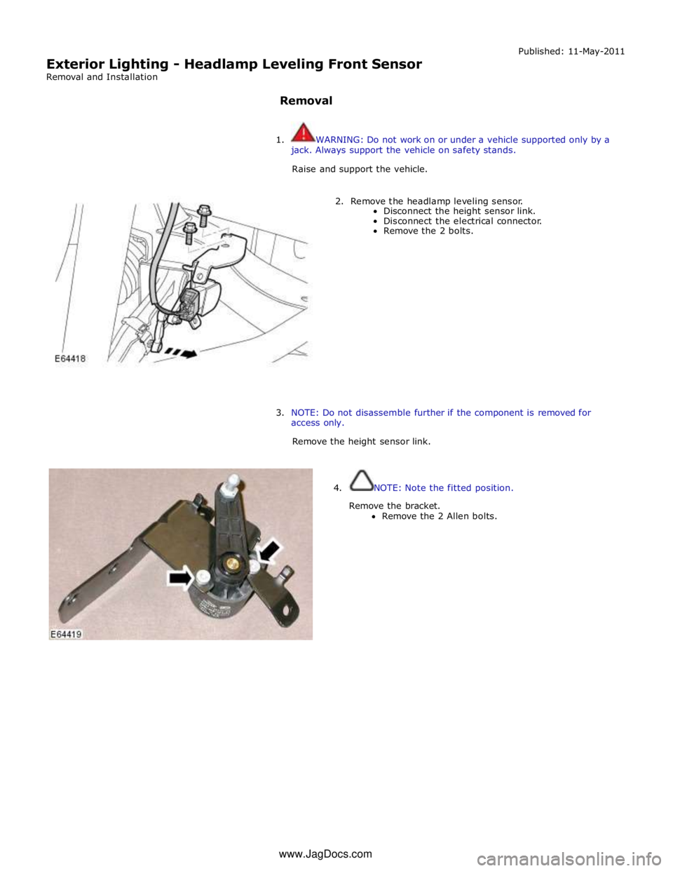
2. Remove the headlamp leveling sensor.
Disconnect the height sensor link.
Disconnect the electrical connector.
Remove the 2 bolts.
3. NOTE: Do not disassemble further if the component is removed for
access only.
Remove the height sensor link.
4. NOTE: Note the fitted position.
Remove the bracket.
Remove the 2 Allen bolts. www.JagDocs.com