2010 JAGUAR XFR height
[x] Cancel search: heightPage 2046 of 3039
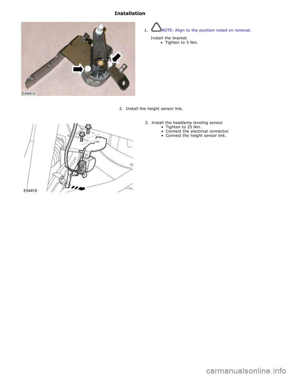
Installation
1. NOTE: Align to the position noted on removal.
Install the bracket.
Tighten to 5 Nm.
2. Install the height sensor link.
3. Install the headlamp leveling sensor.
Tighten to 25 Nm.
Connect the electrical connector.
Connect the height sensor link.
Page 2047 of 3039
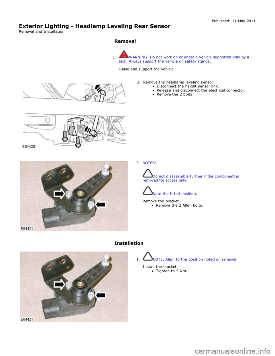
Exterior Lighting - Headlamp Leveling Rear Sensor
Removal and Installation
Removal Published: 11-May-2011
1. WARNING: Do not work on or under a vehicle supported only by a
jack. Always support the vehicle on safety stands.
Raise and support the vehicle.
2. Remove the headlamp leveling sensor.
Disconnect the height sensor link.
Release and disconnect the electrical connector.
Remove the 2 bolts.
3. NOTES:
Do not disassemble further if the component is
removed for access only.
Note the fitted position.
Remove the bracket.
Remove the 2 Allen bolts.
Installation
1. NOTE: Align to the position noted on removal.
Install the bracket.
Tighten to 5 Nm.
Page 2048 of 3039
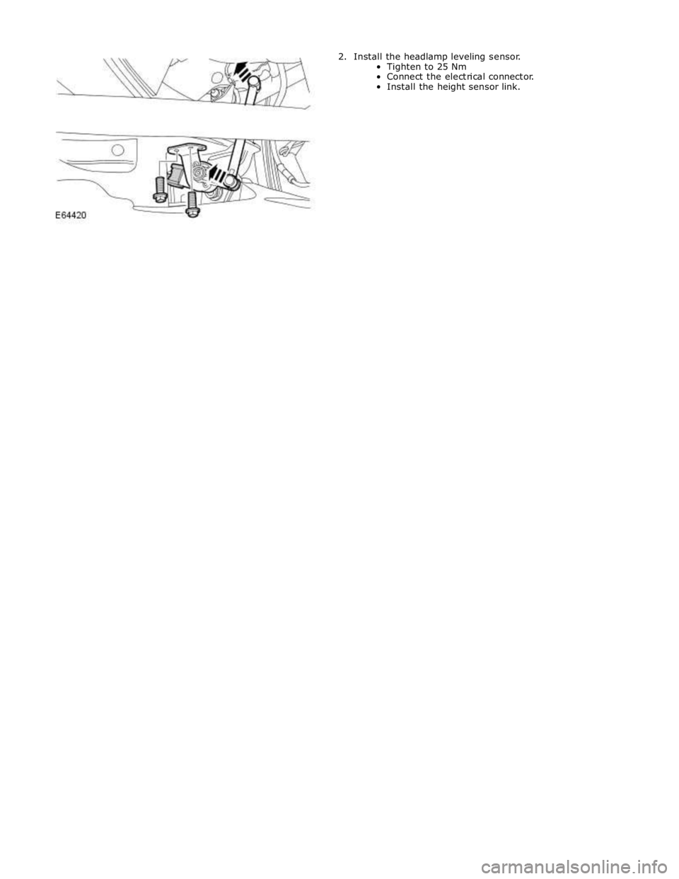
2. Install the headlamp leveling sensor.
Tighten to 25 Nm
Connect the electrical connector.
Install the height sensor link.
Page 2225 of 3039

Front Safety belt shoulder height adjuster retaining bolt 25 19 - Rear safety belt lower retaining bolt 40 30 - www.JagDocs.com
Page 2308 of 3039
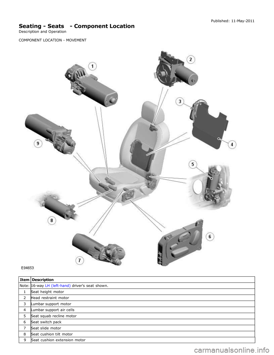
Seating - Seats - Component Location
Description and Operation
COMPONENT LOCATION - MOVEMENT Published: 11-May-2011
Item Description Note: 16-way LH (left-hand) driver's seat shown. 1 Seat height motor 2 Head restraint motor 3 Lumbar support motor 4 Lumbar support air cells 5 Seat squab recline motor 6 Seat switch pack 7 Seat slide motor 8 Seat cushion tilt motor 9Seatcushionextension motor
Page 2313 of 3039

9 Head restraint motor 10 Cushion tilt motor 11 Cushion extension motor 12 Seat slide motor 13 Seat height motor 14 CJB (central junction box)
Page 2315 of 3039
7 Front seat climate control module 8 Passenger seat squab climate module 9 Drivers seat cushion climate module 10 Passenger seat cushion climate module 11 Drivers seat squab climate module 12 Passenger seat cushion heater element 13 Passenger seat squab heater element 14 Drivers seat cushion heater element 15 Drivers seat squab heater element 16 CJB
HEATED SEATS - OPERATION
Heated Front Seats System Operation
The TSD receives a fused power supply from the RJB. One of the 3 seat heat temperature selections made by the driver or passenger using the TSD soft keys are passed from the TSD on the MOST ring to the Information and Entertainment module.
The information and entertainment module processes the information and transmits the request on the medium speed CAN bus to the ATC module.
The cushion heaters have a thermal sensor which supplies a feed back signal back to the CJB. The squab heater elements do not have a thermal sensor and are maintained at the same temperature as the seat cushion elements.
The ATC module reacts to the driver request information received from the information and entertainment module and requests the CJB to activate the seat heaters. The CJB measures the returned temperature signals from the thermal sensors and relays the temperature signals back to the ATC module. The ATC module then uses the measured seat element temperatures to provide closed-loop control of the heater elements to maintain the temperature at one the 3 heat ranges selected.
NOTE: To prevent excessive battery discharge, the heated front seats will only operate when the engine is running.
Heated and Cooled Front Seats
The TSD receives a fused power supply from the RJB. Selections made by the driver using the TSD soft keys are passed from the TSD on the MOST ring to the Information and Entertainment module. The information and entertainment module processes
the information and transmits the request on the medium speed CAN bus to the front seat climate control module. The front seat climate control module is located beneath the RH (right-hand) front seat, on the floor cross member.
The front seat climate control module receives its power supplies from the CJB. Heating and cooling requests are generated using the soft buttons on the TSD. These requests are transmitted to the information and entertainment module over the
MOST ring. The Information and Entertainment module forwards these requests to the front seat climate control module over
the medium speed CAN bus.
The front seat climate control module supplies power to the two climate modules in each seat. The temperature sensor in each
climate module is monitored by the front seat climate control module which uses the temperature information to control the
Peltier cells accordingly and also the blower fans to distribute the heated or cooled air.
NOTE: To prevent excessive battery discharge, the heated and cooled front seats will only operate when the engine is
running.
Electric Driver's Seat Adjustment - Non-Memory Seats
The CJB supplies 3 power supplies to the driver's seat switchpack. The fused supplies provide power for the seat height and squab recline, the seat slide and seat tilt and the lumbar adjustment respectively. The CJB only provides the power to the driver's seat switch pack when the ignition is on (power mode 6).
For the seat movement motors, when the applicable switch is operated, the power is supplied to the applicable side of the
motor and the ground path is completed to operate the motor in the required direction. To move the motor in the opposite
direction the polarity is reversed.
For the lumbar adjustment, when the switch is operated in the inflate position, power is supplied to the pump motor to inflate
the lumbar support. When the switch is operated in the opposite direction, the power energizes a solenoid which in turn opens
a valve to deflate the lumbar support.
Electric Passenger Seat Adjustment ( 8, 10 and 12 way)
The CJB supplies 3 power supplies to the passenger seat switchpack. The fused supplies provide power for the seat height and squab recline, the seat slide and seat tilt and the head restraint and lumbar adjustment respectively. The CJB only provides the power to the passenger seat switch pack when the ignition is on (power mode 6).
For the seat movement and head restraint motors, when the applicable switch is operated, the power is supplied to the
applicable side of the motor and the ground path is completed to operate the motor in the required direction. To move the
Page 2329 of 3039

Symptom Possible Cause Action open circuit Seat movement and memory recall works
correctly however seat lumbar is not
working correctly
NOTE: Seat module
does not control the seat
lumbar function
Seat movement
switch to lumbar
circuits - short,
open circuit Refer to the electrical circuit diagrams and check seat
movement switch to lumbar circuits for short, open
circuit Seat movement from switch pack occurs
in delayed inch mode (seat axis moves
short distance when switch pressed for
longer than 2 seconds and then stops). This behaviour could occur on any seat
axis (slide, height, squab, tilt, headrest
or cushion) when requested
Motor Hall sensor
on affected axis is
not connected or
not receiving
expected signals Check for DTCs, B1B8731, B1B9131, B1B8931, B1B9331,
B106331, B106431. If present then check Hall sensor
feedback circuits between seat motor and seat module
and also check Hall sensor ground circuits for affected
axis. These DTCs are only logged if the axis is
attempted to be moved in both directions. When hall
sensor connection issue fixed press switch on affected
axis for longer than 2 seconds. By keeping the switch
pressed the axis movement should now operate for the
duration of switch-press. Re-calibrate affected seat Seat movement from switch pack occurs
in inch mode. When seat axis movement
is requested from the seat switch pack
the requested seat axis moves a short
distance then stops (does not include
lumbar). This behaviour will occur on ALL
seat axis (slide, height, squab, tilt
headrest and cushion) when requested.
MS CAN communication not possible
MS CAN fault Carry out CAN network integrity test using manufacturer
approved diagnostic system Seat movement from switch pack occurs
in inch mode. When seat axis movement
is requested from the seat switch pack
the requested seat axis moves a short
distance then stops (does not include
lumbar). This behaviour will occur on ALL
seat axis (slide, height, squab, tilt
headrest and cushion) when requested.
MS CAN communication not possible
Seat module is
disconnected from
the CAN Bus Check for Instrument Cluster DTC U020800 'Lost
Communication With Seat Module'. If this DTC is
present, refer to the electrical circuit diagrams and check
seat module power and ground supplies for short, open
circuit. Carry out CAN network integrity tests using the
manufacturer approved diagnostic system Seat movement from switch pack occurs
in inch mode. When seat axis movement
is requested from the seat switch pack
the requested seat axis moves a short
distance then stops (does not include
lumbar). This behaviour will occur on ALL
seat axis (slide, height, squab, tilt
headrest and cushion) when requested.
MS CAN communication not possible
Instrument cluster
is disconnected
from the CAN Bus Check for seat module DTC U015500 'Lost
Communication With Instrument Cluster'. If this DTC is
present, refer to the electrical circuit diagrams and check
instrument cluster power and ground supplies for short,
open circuit. Carry out CAN network integrity tests using
the manufacturer approved diagnostic system Seat movement from switch pack occurs
in inch mode. When seat axis movement
is requested from the seat switch pack
the requested seat axis moves a short
distance then stops (does not include
lumbar). This behaviour will occur on ALL
seat axis (slide, height, squab, tilt
headrest and cushion) when requested.
MS CAN communication not possible
Driver Door Module
is disconnected
from the CAN Bus Check for seat module DTC U019900 'Lost
Communication With Driver Door Module'. If this DTC is
present, refer to the electrical circuit diagrams and check
driver door module power and ground supplies for short,
open circuit. Carry out CAN network integrity tests using
the manufacturer approved diagnostic system Seat movement from switch pack occurs
in inch mode. When seat axis movement
is requested from the seat switch pack
the requested seat axis moves a short
distance then stops (does not include
lumbar). This behaviour will occur on ALL
seat axis (slide, height, squab, tilt
headrest and cushion) when requested.
MS CAN communication not possible
Rear Junction Box
(RJB) is
disconnected from
the CAN Bus Check for seat module DTC U014200 'Lost
Communication With RJB'. If this DTC is present, refer to
the electrical circuit diagrams and check RJB power and
ground supplies for short, open circuit. Carry out CAN
network integrity tests using the manufacturer approved
diagnostic system Seat movement from switch pack occurs
in inch mode. When seat axis movement
is requested from the seat switch pack
the requested seat axis moves a short
distance then stops (does not include
lumbar). This behaviour will occur on ALL
seat axis (slide, height, squab, tilt
headrest and cushion) when requested.
MS CAN communication not possible
Central Junction
Box (CJB) is
disconnected from
the CAN Bus Refer to the electrical circuit diagrams and check CJB
power and ground supplies for short, open circuit. Carry
out CAN network integrity tests using the manufacturer
approved diagnostic system www.JagDocs.com