Page 1240 of 3039
18. Torque: 35 Nm
All vehicles
19. Refer to: Generator - V8 5.0L Petrol (414-02C Generator and Regulator - V8 5.0L Petrol/V8 S/C 5.0L Petrol, Removal and Installation).
20. Refer to: Engine Mount RH (303-01D Engine - V8 S/C 5.0L Petrol, Removal and Installation).
21. Lower the vehicle.
22.
23.
NOTES:
Lubricate
the
union
threads
with
clean
engine
oil.
Do
not tighten
at this
stage.
Remove
and
discard
the
blanking
caps.
Page 1241 of 3039
Bolts 8 Nm
25. Refer to: Air Cleaner Outlet Pipe RH (303-12D Intake Air Distribution and Filtering - V8 S/C 5.0L Petrol, Removal and Installation).
26.
27. 28.
29. Refer to: Engine Cover - V8 5.0L Petrol/V8 S/C 5.0L Petrol (501-05 Interior Trim and
Page 1243 of 3039
Fuel Charging and Controls - V8 S/C 5.0L Petrol - Throttle Body
Removal and Installation
Removal
NOTE: Removal steps in this procedure may contain installation details. Published: 08-Nov-2013
1. WARNING: Do not work on or under a vehicle supported only by a jack.
Always support the vehicle on safety stands.
Raise and support the vehicle.
2. Refer to: Battery Disconnect and Connect (414-01 Battery, Mounting and Cables, General Procedures).
3. Refer to: Cooling System Partial Draining, Filling and Bleeding (303-03E,
General Procedures).
4. Refer to: Engine Cover - V8 5.0L Petrol/V8 S/C 5.0L Petrol (501-05 Interior Trim and Ornamentation, Removal and Installation).
5. Refer to: Air Cleaner Outlet Pipe (303-12E, Removal and Installation).
6.
Page 1251 of 3039
7. CAUTIONS:
Make sure that the accessory drive belt is correctly
aligned to the pulleys. Failure to follow this instruction may
result in damage to the vehicle.
Clean and inspect the accessory drive belt pulleys for
damage.
NOTES:
Some variation in the illustrations may occur, but the
essential information is always correct.
Engine shown removed for clarity.
Note the fitted position.
Installation
1. To install, reverse the removal procedure.
Page 1255 of 3039
Published: 11-May-2011
Accessory Drive - V8 S/C 5.0L Petrol - Supercharger Belt Idler Pulley
Removal and Installation
Removal
NOTE: Removal steps in this procedure may contain installation details.
1. Refer to: Battery Disconnect and Connect (414-01 Battery, Mounting and Cables, General Procedures).
2. Refer to: Air Cleaner Outlet Pipe RH (303-12D Intake Air Distribution and Filtering - V8 S/C 5.0L Petrol, Removal and Installation).
3. Refer to: Air Cleaner Outlet Pipe T-Connector (303-12D Intake Air Distribution and Filtering - V8 S/C 5.0L Petrol, Removal and Installation).
Installation
4. NOTES:
Note the fitted position.
Engine shown removed for clarity.
5. Torque: 40 Nm
1. CAUTION: Make sure the supercharger belt is correctly aligned to the
pulleys. Failure to follow this instruction may result in damage to
the vehicle.
To install, reverse the removal procedure.
Page 1259 of 3039
Published: 11-May-2011
Starting System - V8 5.0L Petrol/V8 S/C 5.0L Petrol - Starting System - Component Location
Description and Operation
NOTE: Installation on supercharged engine shown, installation on naturally aspirated engine similar.
COMPONENT LOCATION
Page 1262 of 3039
When the ECM receives a crank request, it energizes the starter relay in the EJB (engine junction box). The energized starter relay supplies 12 V power (fed via the 250 A megafuse in the BJB (battery junction box)) to energize the pull-in coil of the
starter solenoid. Once activated, the pull-in coil engages the solenoid plunger, which engages the pinion with the ring gear.
The plunger then closes the solenoid circuit, feeding power from the 400 A megafuse in the BJB to the starter motor.
Page 1263 of 3039

Published: 11-May-2011
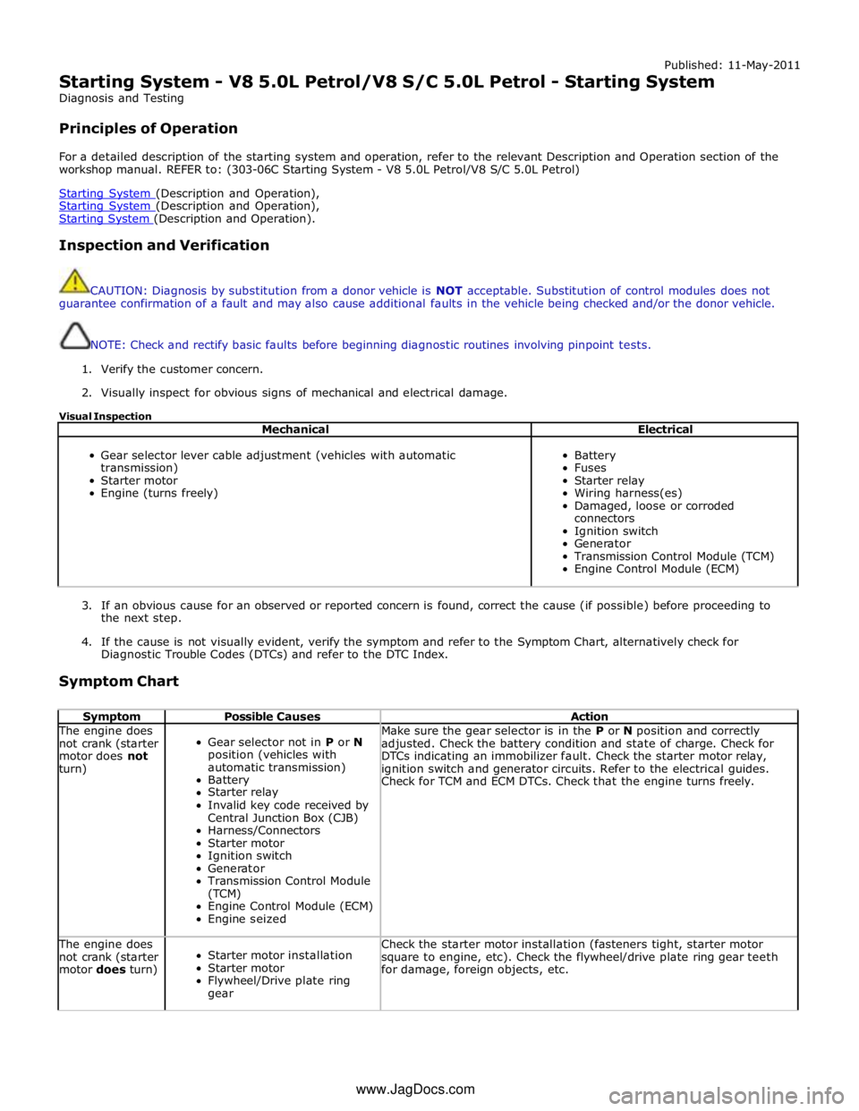
Starting System - V8 5.0L Petrol/V8 S/C 5.0L Petrol - Starting System
Diagnosis and Testing
Principles of Operation
For a detailed description of the starting system and operation, refer to the relevant Description and Operation section of the
workshop manual. REFER to: (303-06C Starting System - V8 5.0L Petrol/V8 S/C 5.0L Petrol)
Starting System (Description and Operation), Starting System (Description and Operation), Starting System (Description and Operation).
Inspection and Verification
CAUTION: Diagnosis by substitution from a donor vehicle is NOT acceptable. Substitution of control modules does not
guarantee confirmation of a fault and may also cause additional faults in the vehicle being checked and/or the donor vehicle.
NOTE: Check and rectify basic faults before beginning diagnostic routines involving pinpoint tests.
1. Verify the customer concern.
2. Visually inspect for obvious signs of mechanical and electrical damage.
Visual Inspection
Mechanical Electrical
Gear selector lever cable adjustment (vehicles with automatic
transmission)
Starter motor
Engine (turns freely)
Battery
Fuses
Starter relay
Wiring harness(es)
Damaged, loose or corroded
connectors
Ignition switch
Generator
Transmission Control Module (TCM)
Engine Control Module (ECM)
3. If an obvious cause for an observed or reported concern is found, correct the cause (if possible) before proceeding to
the next step.
4. If the cause is not visually evident, verify the symptom and refer to the Symptom Chart, alternatively check for
Diagnostic Trouble Codes (DTCs) and refer to the DTC Index.
Symptom Chart
Symptom Possible Causes Action The engine does
not crank (starter
motor does not
turn)
Gear selector not in P or N
position (vehicles with
automatic transmission)
Battery
Starter relay
Invalid key code received by
Central Junction Box (CJB)
Harness/Connectors
Starter motor
Ignition switch
Generator
Transmission Control Module
(TCM)
Engine Control Module (ECM)
Engine seized Make sure the gear selector is in the P or N position and correctly
adjusted. Check the battery condition and state of charge. Check for
DTCs indicating an immobilizer fault. Check the starter motor relay,
ignition switch and generator circuits. Refer to the electrical guides.
Check for TCM and ECM DTCs. Check that the engine turns freely. The engine does
not crank (starter
motor does turn)
Starter motor installation
Starter motor
Flywheel/Drive plate ring
gear Check the starter motor installation (fasteners tight, starter motor
square to engine, etc). Check the flywheel/drive plate ring gear teeth
for damage, foreign objects, etc. www.JagDocs.com